Photo Realistic Rendering
Modelling, Assembly and Photo Realistic Rendering of An American Chopper Motorcycle
Objective:- The main objective of this project is to create various 3D parts of an American Chopper Motorcycle in a 3D CAD software(SOLIDWORKS), assigning them the proper appearance, colour, decals. Finally creating assembly of the parts with proper mates after that Rendering that assembly with suitable environment and lightning to a high quality detailed final rendered image of the motorcycle using Solidworks Photoview 360 and Solidworks visualize.
American Chopper:- A chopper is a type of custom motorcycle which emerged in California in the late 1950s. A chopper employs radically modified steering angles and lengthened forks for a stretched-out appearance. They can be built from an original motorcycle which is modified ("chopped") or built from scratch. Some of the characteristic features of choppers are long front ends with extended forks often coupled with an increased rake angle, hard tail frames (frames without rear suspension), very tall "ape hanger" or very short "drag" handlebars, lengthened or stretched frames, and larger than stock front wheels.
Introduction:- This project explains the designing of American chopper using the CAD software SOLIDWORKS from sketching the parts and modelling them to final rendering of the assembly to give a photo realistic view.
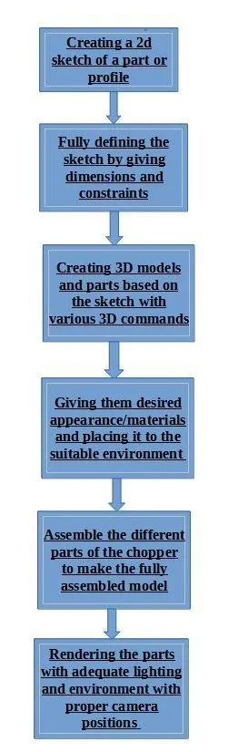
Design Methodology:- The methodology which is used from beginning to the final render of the Chopper is simple straight forward and is given below with the help of a flow chart
Features/tools used in the designing of Chopper
-
Boss Extrude: This feature is used to expand the object in 3D according to sketch plane.
-
Extrude Cut: Extrude cut feature used to cut/remove the 3d object in linear path according to sketch.
-
Fillet: Fillet is a feature used for making round internal or external edges to avoid sharp edges and make it smooth.
-
Lofted Boss/Base: Lofted boss is a feature used to achieve Complex Shapes. It does this by interpolating surfaces between various cross-sections of a model. These cross-sections can be sketches, faces, or edges.
-
Split: Split tool is used to split single solid part into two solid parts. It is used to project an entity onto other surfaces or curved/planar faces.
-
Dome: Dome is a feature used to make dome shaped extrude including elliptical dome.
-
Shell: Shell feature is used to make to hollow space in solid part by selecting outer wall of the solid part and so removes the inner parts. It is also used to reduce the specific thickness.
-
Combine: Combine tool is used to make integration of two solid parts which intersect each other as same solid part.
-
Chamfer: Chamfer is used to make a sharp edge or corner slightly tapered rather than being a perfect square.
-
Linear Pattern: The linear parent is used to create a different number of instances required to create the pattern linearly.
-
Curve Driven Pattern: Curve driven pattern is used to make any pattern which followed by the curve is sketched before.
-
Circular pattern: Circular pattern is a feature used to make 3d feature into circular pattern according to number of insistences.
-
Revolve boss base: Revolve feature is used to make cylindrical or circular 3D extrude along with a given reference axis as per drawn sketch.
-
Revolve cut: Revolve cut is used to cut or reduce the extrude of cylindrical round surface.
-
Move/copy body: This feature is used to move/copy the 3D body to one place to another place.
-
Mirror: Mirror is used to mirror a feature or body by reference of the selected plane.
-
Sweep: This feature is used to sweep any kind of fully defined sketch along with the path.
-
Sweep cut: Sweep cut is same as sweep feature but its directly proportional to sweep which makes a cut along with the sweep path.
-
Swept Surface: It is used to make a surface along with a path the curve is driven.
-
Boundary Surface: Boundary surface is used to make a surface in between two finished surfaces.
-
Loft Surface: Loft surface is used to make loft in between two profiles along with guide path.
-
Knit surface: Knit surface is used to knit the two free edges or open edges of the surfaces together also it reduces the gap between the two edges of the surface.
-
Surface Trim: Primarily used to cut away material from a surface, and provides two modes: Standard and Mutual.
-
Projection Curve: Projection curve is a 3D curve which is projected on the basis of the two different 2D curves in two different planes.
-
Blocks: You can make save, edit and insert blocks from the drawing items and sketch entities that you use often such as standard notes, title blocks, label positions and so on you can attach blocks to geometry or to drawing views
Trim entities: it is used to trim the unwanted lines or extended entities in the sketch.
Individual Parts which are used in Chopper Assembly:-
-
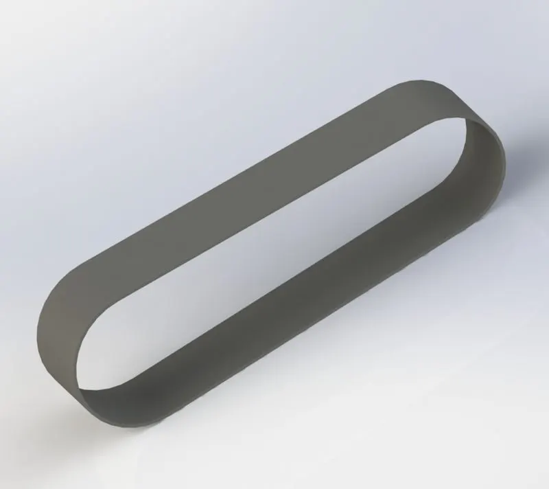
Transmission Belt:- A belt is a loop of flexible material used to link two or more rotating shafts mechanically, most often parallel. Belts may be used as a source of motion, to transmit power efficiently or to track relative movement.
Features Used- Boss Extrude
Part Image Rendered Image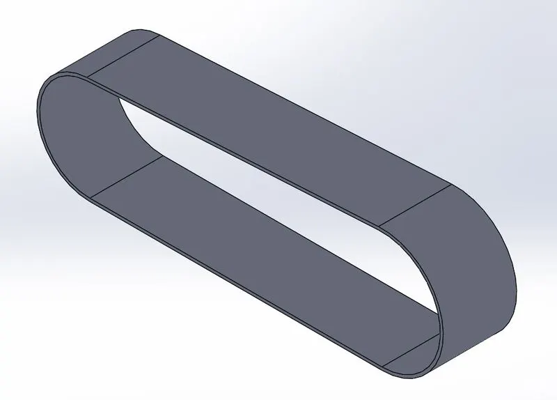
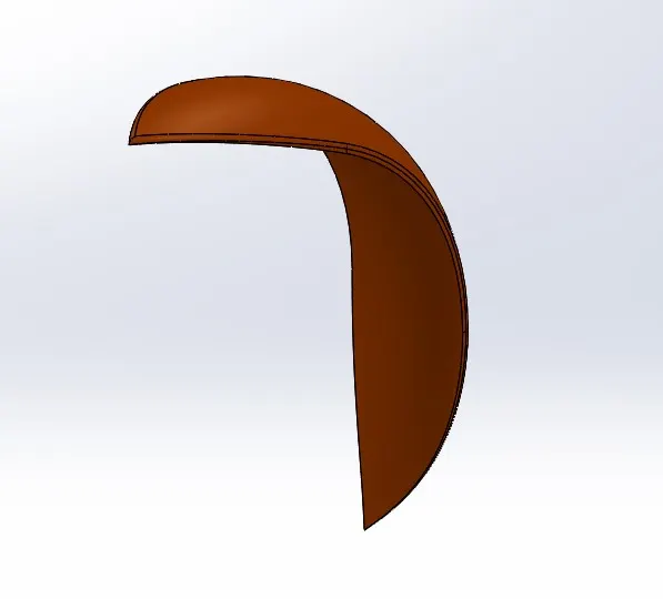
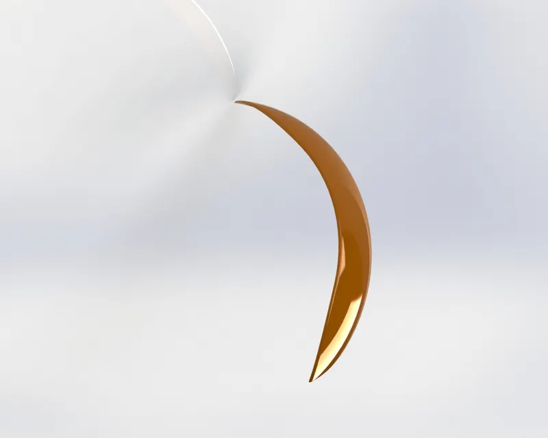
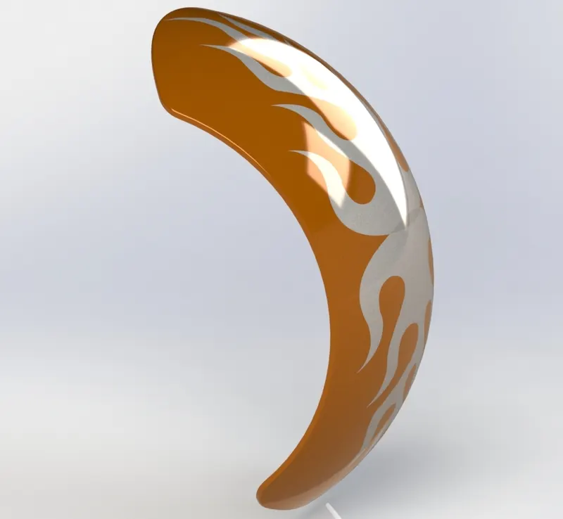
Front Fender:-Fenders (or “mudguards” as people outside the U.S. call them) are what will keep you from having a skunk stripe on your backside if you ride in the rain, and a front fender will help protect your feet and ankles from spray if you're riding in the rain or even through a puddle.
Features Used- Revolve, Split, Fillet
Part Image Rendered Image
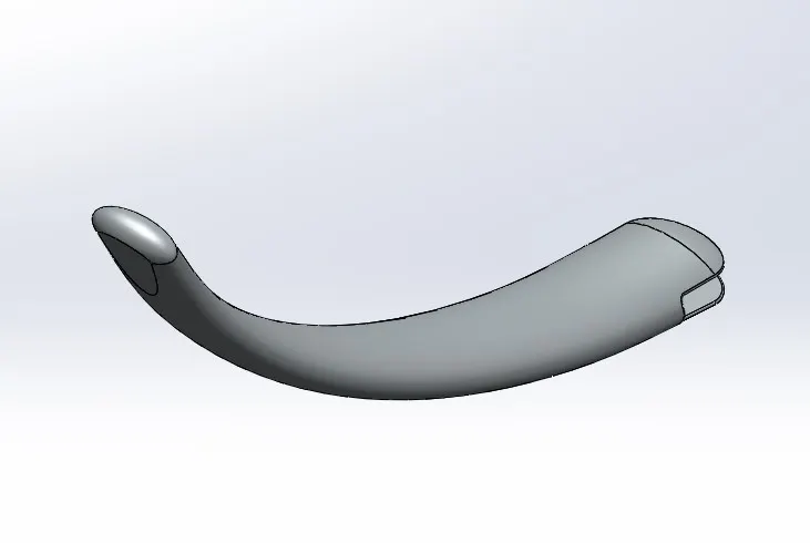
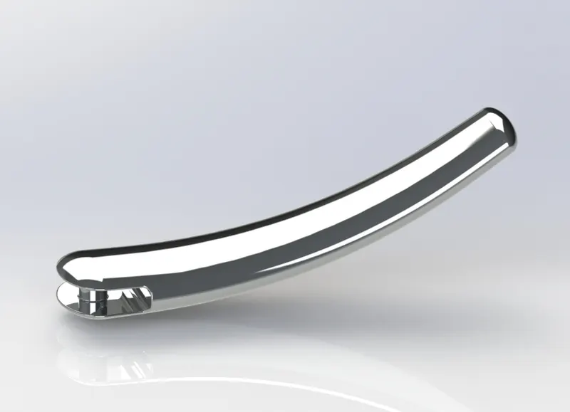
Kickstand:-A kickstand is a device on a bicycle or motorcycle that allows the bike to be kept upright without leaning against another object or the aid of a person.
Features Used- Loft, Dome,Extrude-Cut, Split, Extrude, Fillet
Part Image Rendered Image
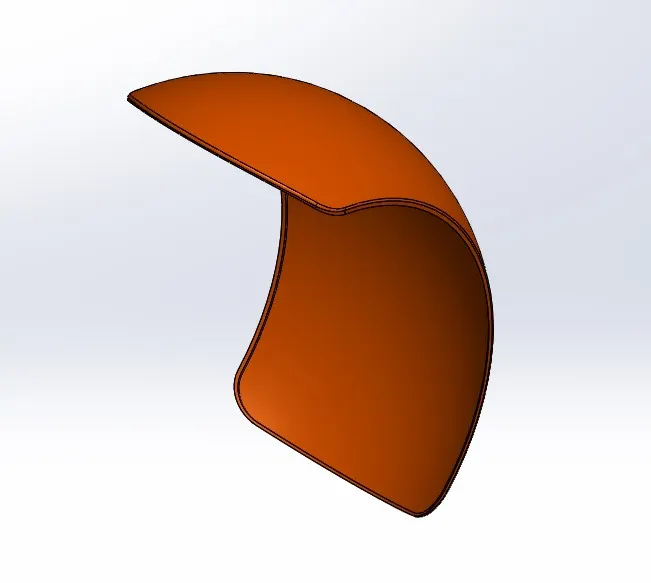
Rear Fender:-Fender is the American English term for the part of an automobile, motorcycle or other vehicle body that frames a wheel well (the fender underside). Its primary purpose is to prevent sand, mud, rocks, liquids, and other road spray from being thrown into the air by the rotating tire.
Features Used-Revolve, Split, Fillet,Shell
Part Image Rendered Image
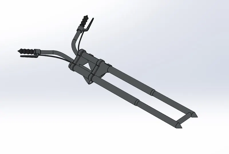
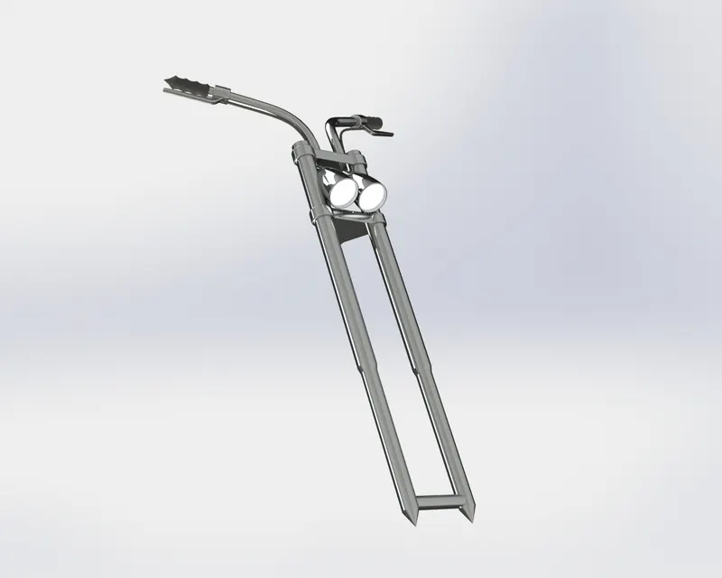
Front Fork:-A motorcycle fork connects a motorcycle's front wheel and axle to its frame, typically via a yoke, also known as a triple clamp, which consists of an upper yoke joined to a lower yoke via a steering stem, a shaft that runs through the steering head, creating the steering axis. Most forks incorporate the front suspension and front brake, and allow the front wheel to rotate about the steering axis so that the bike may be steered.
Features Used- Revolve, Extrude, Fillet, Linear Pattern, Extrude-cut, Dome, Revolve-Cut, Body-Move, Projected curve, Sweep, Mirror, Combine
Part Image Rendered Image
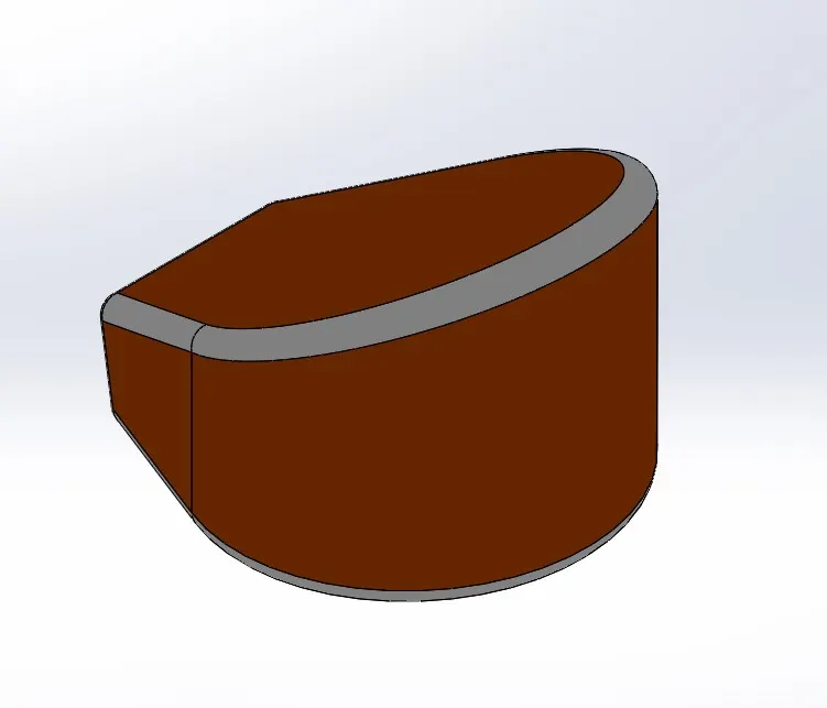
Oil Tank:- The oil tank stores the oil until it needs to be used by the heating system. Oil tanks are available in a variety of sizes and shapes, including horizontal and vertical tanks. They might be located above or underground.
Features Used-Extrude, Combine, Fillet, Shell.
Part image Rendered Image
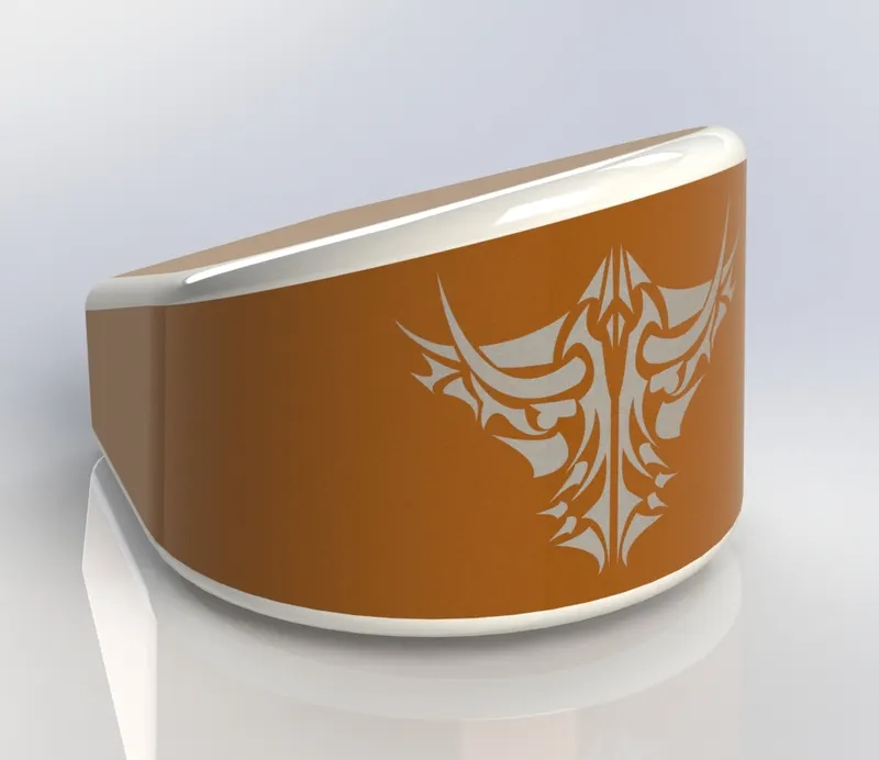
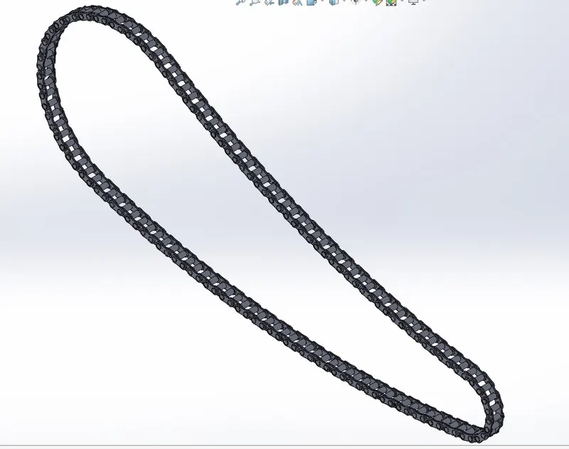
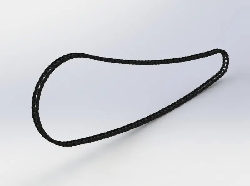
Chain:- Chain of the motorcycle transfers the power from the engine to the rear wheel, moving the motorcycle forward. This pulling force is transmitted via the side plates of the chain through the chain's pins to the rollers. The distance between the centres of the pins is equal to the distance between the centres of the sprocket teeth.
Features Used-Extrude, Fillet, Chamfer, Linear Pattern
Part Image Rendered Image
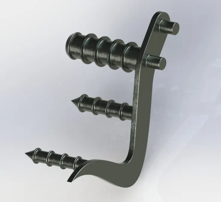
Pedal:-The Main Function Is To Work As Anti Skid And Prepare Grip To The Foot Of Driver Running The Vehicle.
Features Used-Extrude, Fillet, Chamfer, Linear Pattern
Part Image Rendered Image
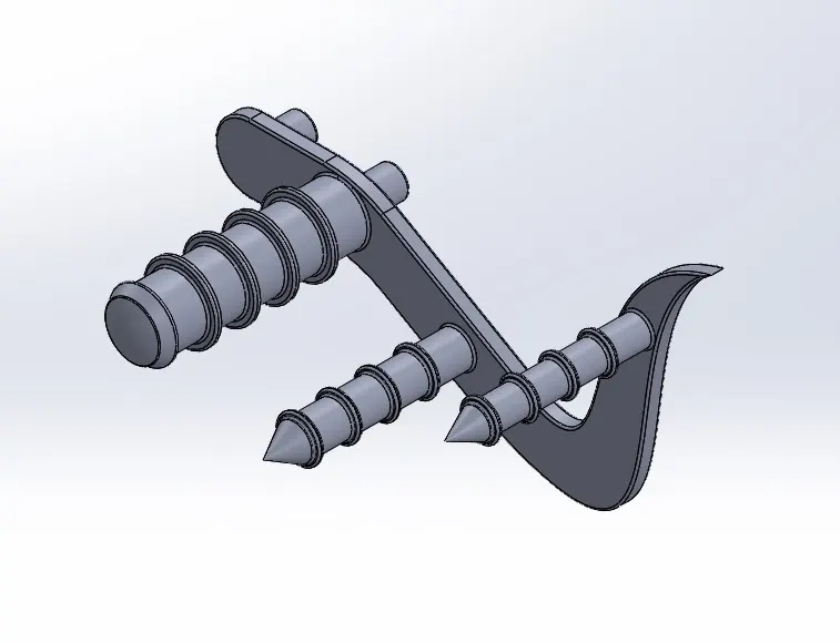
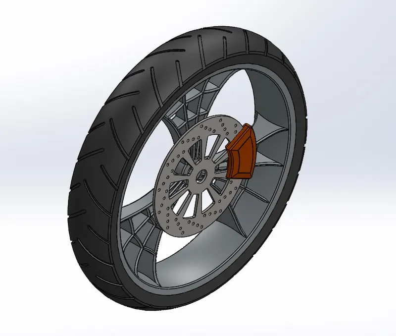
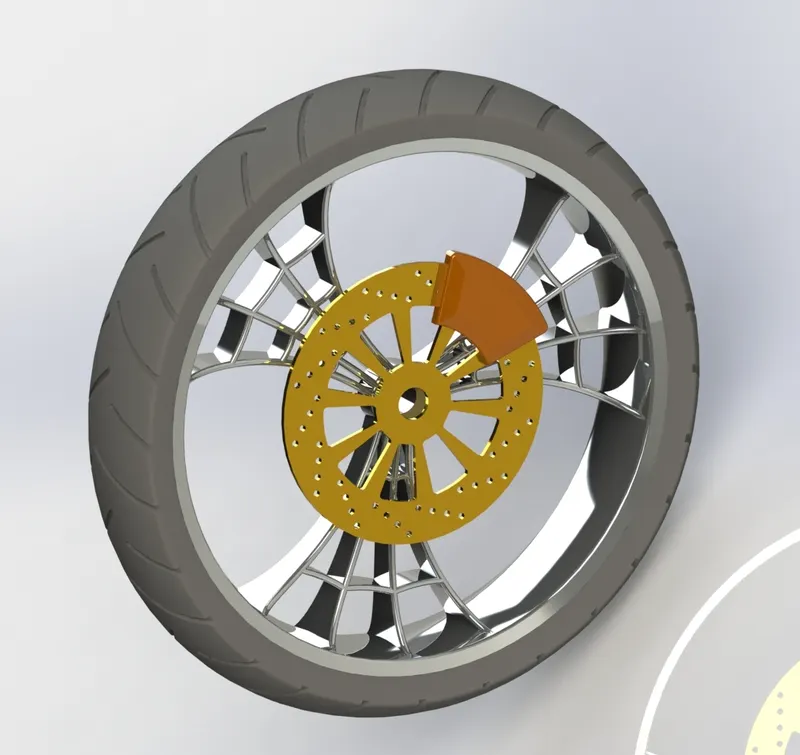
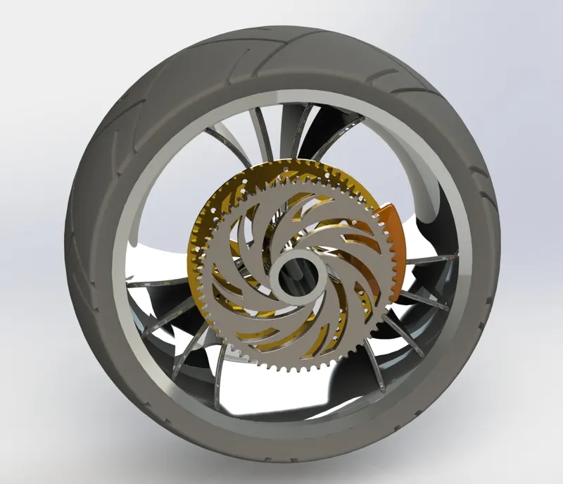
Front Wheel:-This front wheel is Spider webbed designed, given a very cool unique looks and the shiny chrome appearance, it is less in width as compared to rear wheel.
Features Used-Extrude, Extrude-cut, Revolve-cut, Circular Pattern, Revolve, Chamfer, combine
Part Image Rendered Image
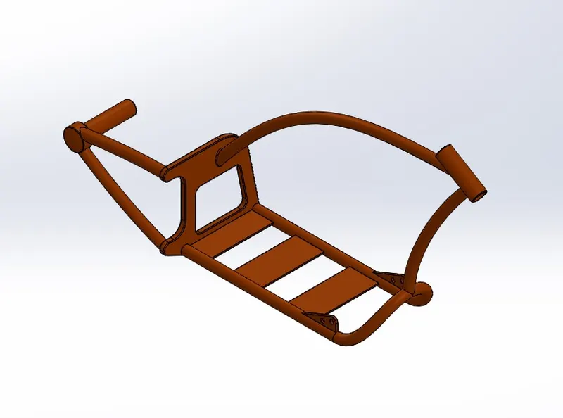
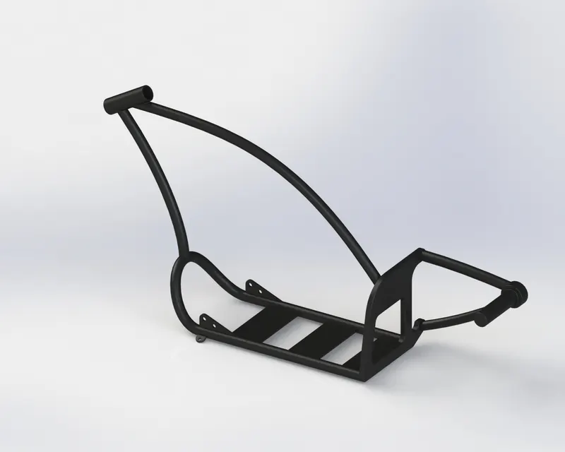
Chassis:-A motorcycle's chassis or frame forms its skeleton. All the components of a motorcycle, like the suspension, wheels, fuel tank, seats, handlebars etc., are attached to this base structure which lends a motorcycle its strength and ability to handle well.
Features Used-Projected curve, sweep, Mirror, Extrude, Extrude-Cut, Chamfer, Fillet, Dome, Split, Combine
Part Image Rendered Image
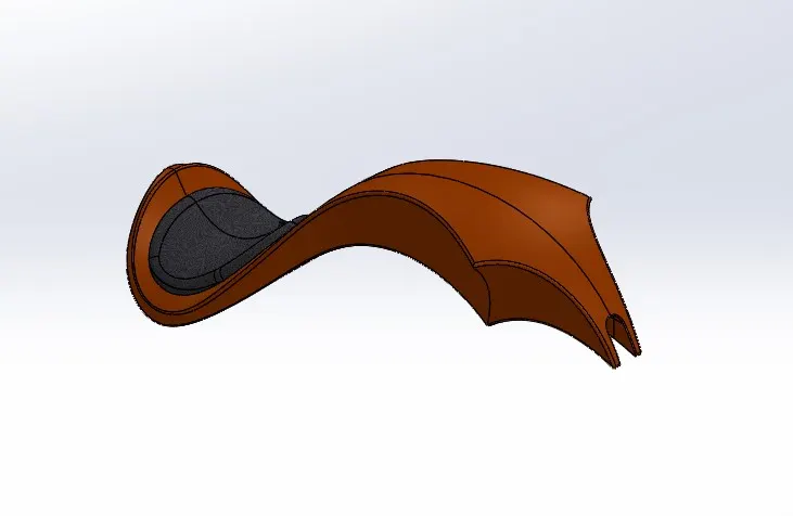
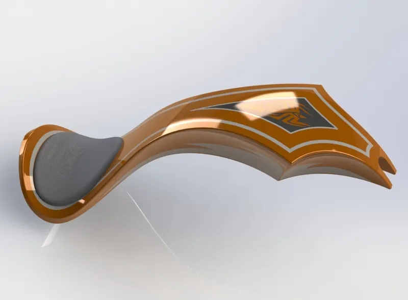
Gas Tank:-A Gas Tank is a safe container for flammable fluids. Though any storage tank for fuel may be so called, the term is typically applied to part of an engine system in which the fuel is stored and propelled (fuel pump) or released (pressurized gas) into an engine.
Features Used-Surface Modelling, Surface sweep, surface trim, projected curve, surface loft, surface knit, sweepcut.
Part Image Rendered image
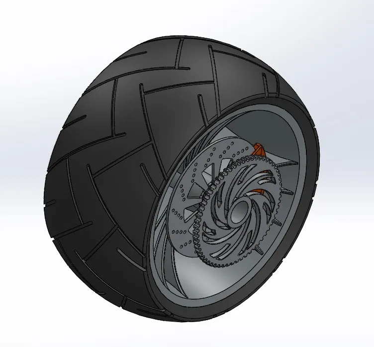
Rear Wheel:-Same as the front wheel the rear wheel is also given the cool spider web design and the classic chrome looks for its rim.
Features Used-Revolve, Extrude, Extrude-cut, Circular pattern, Combine, revolve, fillet, chamfer.
Part Image Rendered Image
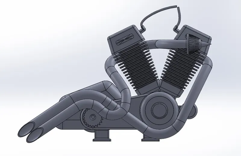
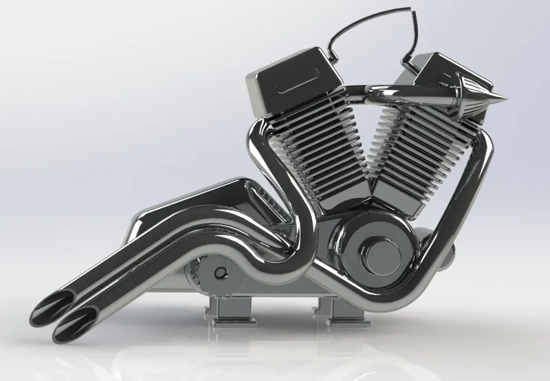
Engine:-Motorcycle engines work the same way that car engines do. They consist of pistons, a cylinder block and a head, which contains the valve train. The pistons move up and down in the cylinder block, driven by explosions of a fuel-air mixture that has been ignited by a spark.
Features Used-Extrude, fillet, revolve, circular pattern, dome, extrude-cut, chamfer, mirror, split, projected curve, composite curve.
Part Image Rendered Image
Chopper Assembly images before rendering:-
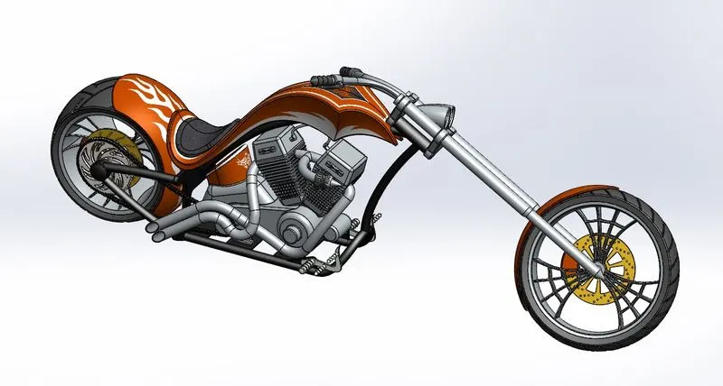
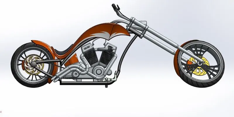
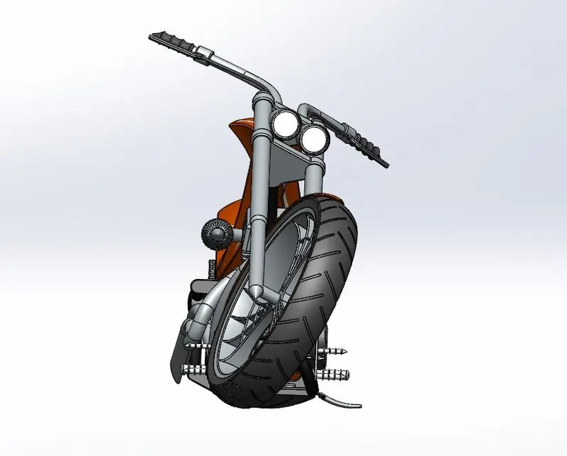
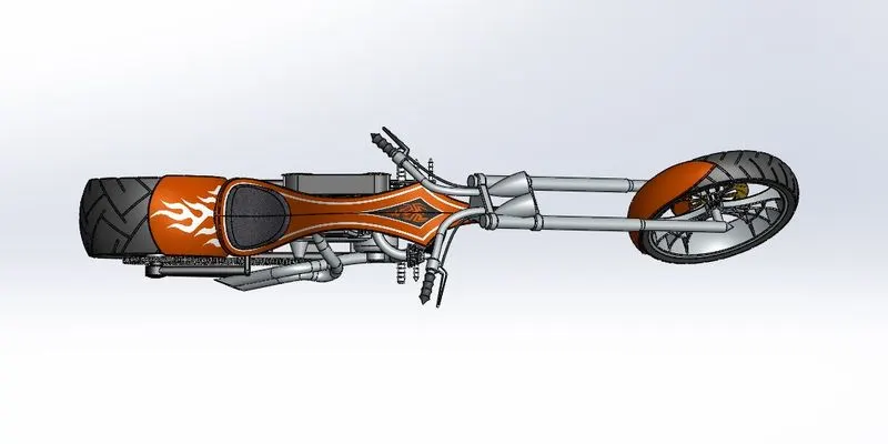
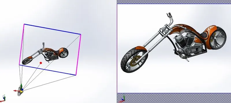
Chopper Assembly images after rendering:-
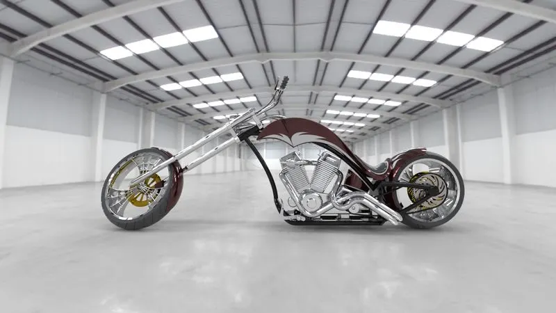
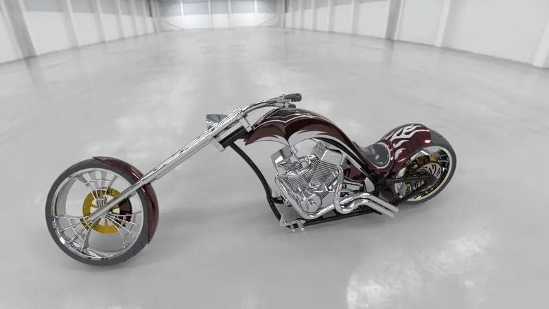
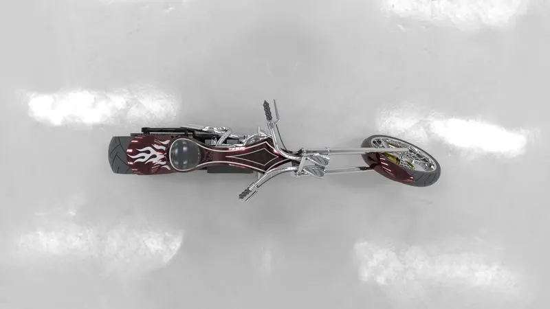
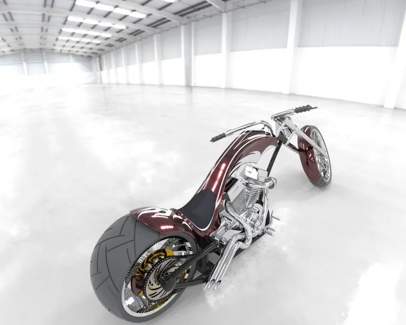
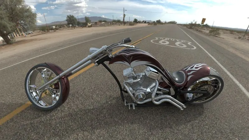
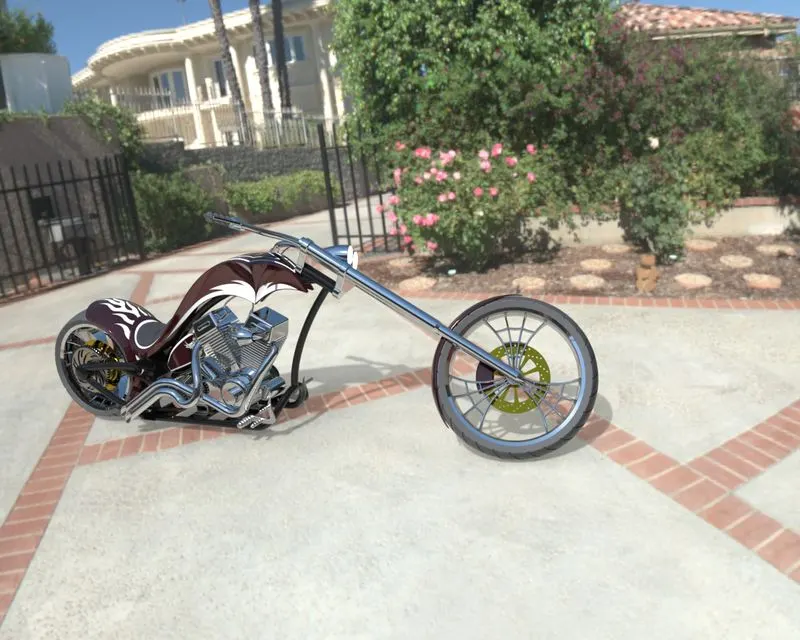
Conclusion:-Thus, the parts of the American Chopper are designed and assembled using Solidworks and are rendered to photorealistic
images using Photoview 360 and Solidworks Visualize
Report Created by:- Rishabh Soni