Radar Mast & Final Assembly of Yacht
RADAR MAST
MODELLING OF YACHT USING SOLIDWORKS
OBJECTIVE: To model the different parts of the yacht,assembling the modelled parts and rendering it using the SOLIDWORKS software.
INTRODUCTION: A yacht is larger, recreational boat or ship.Yachts can range from about 35 feet in length all the way up to 160+ feet in length, however, most will be somewhere in the middle. Anything over 160 feet would be considered as a “Superyacht".Yacht can be of various types such as Sailing Yacht,Motor Yacht,Gulet Yacht,Open Yacht,Luxury Yacht,Sports Yacht,Catamaran Yacht.
DESIGN METHODOLOGY:
COMMANDS USED:
1.EXTRUDE BOSS/BASE:It is used in extruding the sketch profile in one or more direction to create a solid feature.
2.CUT EXTRUDE:It cuts a solid modelby extruding sketch profile in one or more direction.
3.REVOLVE:It is used in revolving the sketch profile around a particular axis to create a solid feature.
4.FILLET:It creates a round internal or external edges around the edges of the face.
5.CHAMFER:It creates an angle or distance edges around the edges of the face.
6.SWEEP:It helps in sweeping a closed profile along a closed or open path.
7.DOME:It is used to create a circular or elliptical face over a selected portion.
8.COMBINE:It is used to combine two or more bodies.
9.SPLIT:It is used to removal or trimming of part from the selected sketch
10.LINEAR AND CIRCULAR PATTERN:It is used to create circular or linear pattern of the selected sketch along the same path.
11.MIRROR:It mirrors a face or body about the selected mirror plane.
12.CURVE DRIVEN PATTERN:It creates a pattern of the selected sketch profile along a curve.
13.COMPOSITE CURVE:It is the combination of the two projected curves.
14.CUT REVOLVE:It cuts a solid model by revolving sketch profile around axis in one or two direction.
15.LOFT:It creates a shape by making transitions between multiple profiles and guide curves.
16.SHELL:It hollows out a part,leaves open the faces we select and creates thin walled features.
17.SURFACE TRIM:It trims or remove material from selected surface sketch.
18.SURFACE KNIT:Knits two or more bodies so that no gap is in between them and forms a solid model.
19.SURFACE EXTRUDE:Extrudes the boundary edges of a face of a solid body or edges of a surface body in a customised direction.
20.RULED SURFACE:This feature inserts a ruled surface from the selected edges.
21.EXTEND SURFACE:Extends the edge,multiple edges of a face on a surface based on end conditions & extension type.
22.SURFACE FILL: Constructs a surface patch within a boundary defined by existing model edges,sketches or curves.
23.BOUNDARY SURFACE: This feature Creates a boundary surface between profiles in two directions.
24.SURFACE LOFT: This feature Creates a lofted surface between two or more profiles.
25.OFFSET SURFACE: This feature Creates offset surfaces using one or more contiguous faces.
26.SWEPT SURFACE: This feature creates a surface by sweeping an open or closed profile along an open or closed path.
27.DELETE FACE: This feature deletes the selected face.
28.MOVE/COPY:This feature moves or copies the particular solidbody about a particular plane
29.3D SKETCH: A 3D sketch is non-planar.It has 6 degrees of freedom.It can be used to guide the sweep or loft in 3D.
30.SPLIT ENTITIES:It splits the sketch entity into two entities by adding split point.
DESCRIPTION:
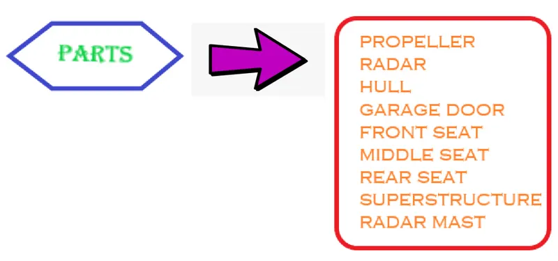
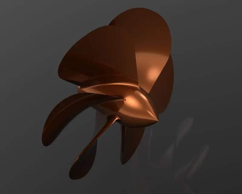
1.PROPELLER: A propeller is a type of fan which converts rotational motion into thrust thus transmits power.A pressure difference is generated between the airfoil shaped blades.
FEATURES USED:
*LOFT
*REVOLVE BOSS/BASE
*CUT EXTRUDE
*CIRCULAR PATTERN
*FILLET
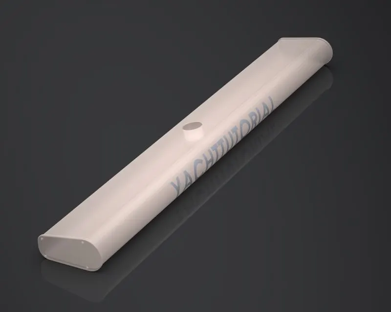
2.RADAR: Radar is used to detect other ships and land barriers.
FEATURES USED:
*BOSS EXTRUDE
*CUT EXTRUDE
*SKETCH PATTERN
*SPLIT LINE
*MIRROR
*FILLET
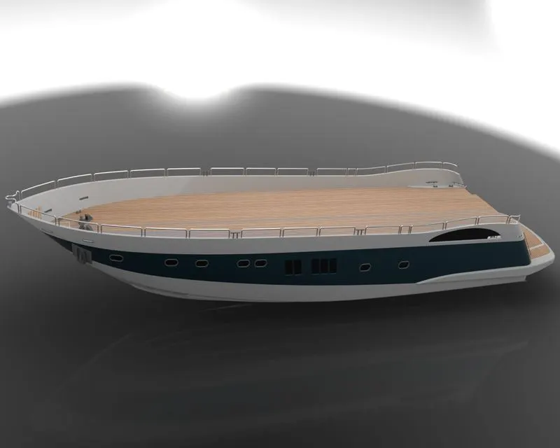
3.HULL: Hull is the watertight body of a ship.The hull may open at the top completely or partially covered by a deck.
FEATURES USED:
*PROJECTED CURVE
*SURFACE LOFT
*SURFACE TRIM
*SURFACE EXTRUDE
*SURFACE KNIT
*SRFACE FILL
*SHELL
*CUT EXTRUDE
*FILLET
*CHAMBER
*SWEEP BOSS/BASE
*BOSS/BASE EXTRUDE
*REVOLVE
*DOME
*HELIX/SPIRAL
*LINEAR PATTERN
*ADD/DELETE FACE
*THIN EXTRUDE
*SPLIT
*SPLIT LINE
*OFFSET SURFACE
*MIRROR
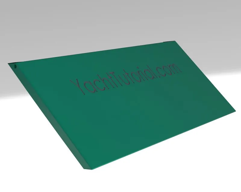
4.GARAGE DOOR: It is the door of the garage of the yacht.
FEATURES USED:
* CUT EXTRUDE
* SHELL
* MIRROR
* FILLET
5.FRONT SEAT: It is the seat located at the front side of the yacht.
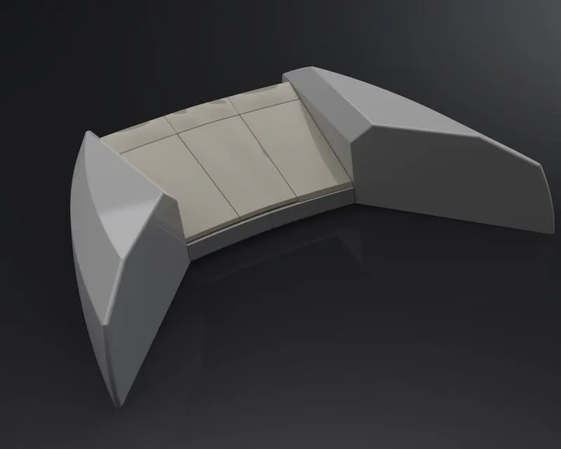
FEATURES USED:
*INSERT PART
*SURFACE SWEEP
*SURFACE EXTRUDE
*SURFACE TRIM
*SURFACE FILL
*SURFACE LOFT
*SURFACE KNIT
*CHAMFER
*REVOLVE
*CUT EXTRUDE
*FILLET
*DOME
*MIRROR
6.MIDDLE SEAT: It is the seat located at the middle of the yacht.
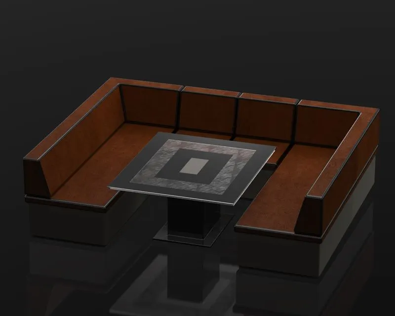
FEATURES USED:
*INSERT PART
*BOSS EXTRUDE
*CHAMFER
*FILLET
*MIRROR
*CUT EXTRUDE
7.REAR SEAT: It is located at the rear side of the yacht.
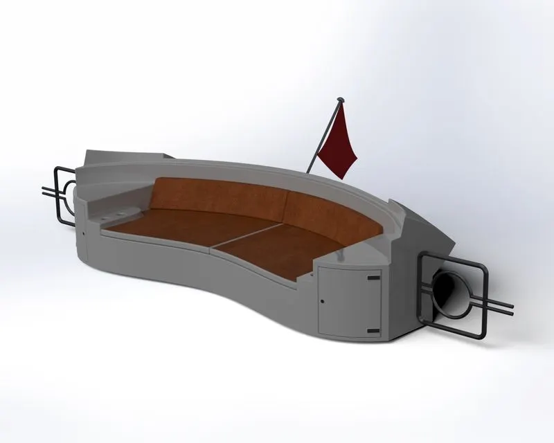
FEATURES USED:
*SURFACE SWEEP
*SURFACE TRIM
*SURFACE OFFSET
*RULED SURFACE
*SURFACE KNIT
*SURFACE EXTEND
*SURFACE EXTRUDE
*SURFACE LOFT
*BOSS/BASE EXTRUDE
*CUT EXTRUDE
*CHAMFER
*BOSS SWEEP
*REVOLVE BOSS/BASE
*FILLET
*MIRROR
8.SUPERSTRUCTURE:It is an upward extension of an existing structure above a base line of the hull.
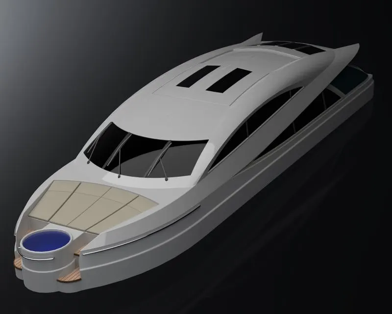
FEATURES USED:
*SURFACE SWEEP
*SURFACE KNIT
*SURFACE LOFT
*SURFACE TRIM
*SURFACE FILL
*SURFACE EXTRUDE
*PROJECT CURVE
*SURFACE EXTEND
*CUT EXTRUDE
*BOSS/BASE EXTRUDE
*THIN EXTRUDE
*ADD/FACE DELETE
*RULED SURFACE
*FILLET
*CHAMFER
*SURFACE OFFSET
*THICKNESS
*DOME
*SPLIT LINE
*MIRROR
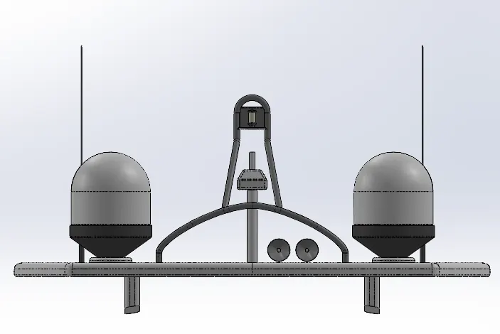
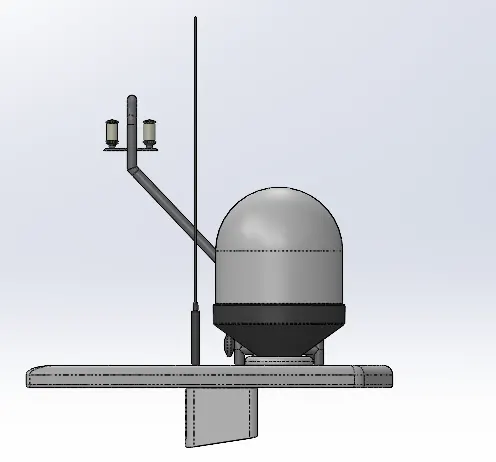
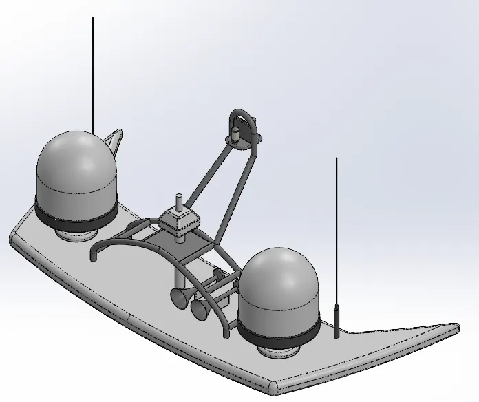
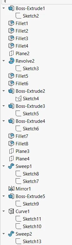
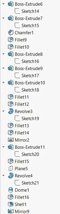
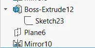
9.RADAR MAST: It supports the radar,antennas,satellite domes and lights.

FEATURES USED:
*BOSS/BASE EXTRUDE
*REVOLVE
*FILLET
*BOSS SWEEP
*PROJECT CURVE
*CHAMFER
*CUT EXTRUDE
*MIRROR.
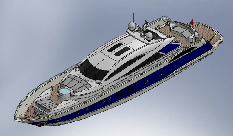
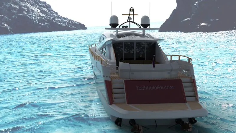
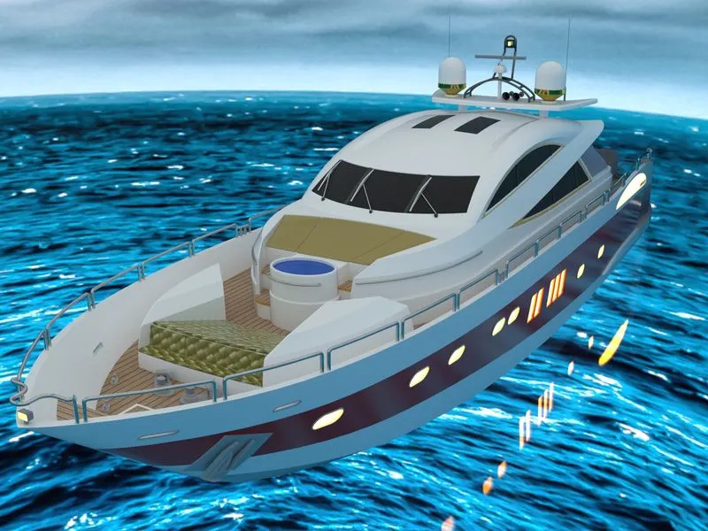
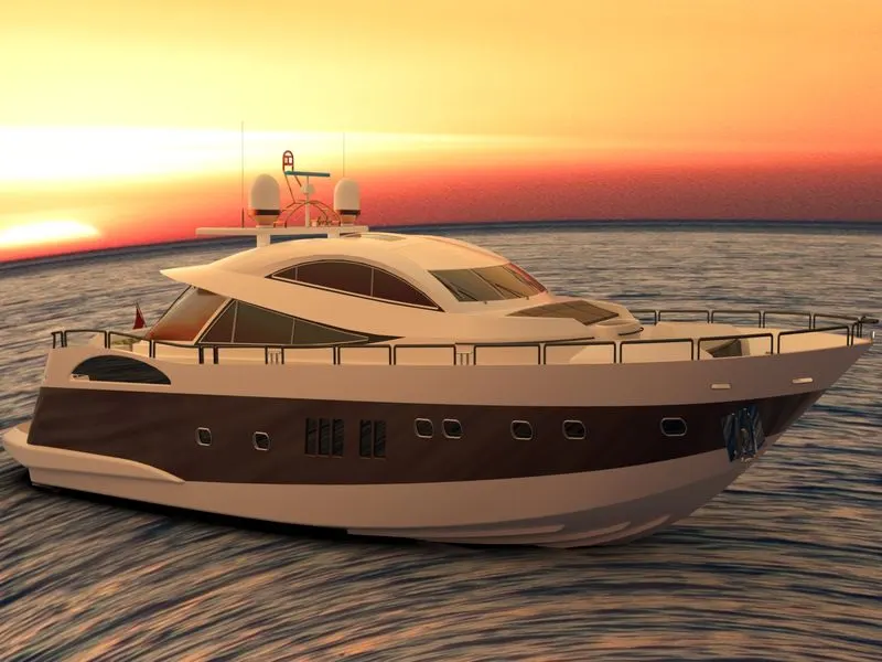
ASSEMBLY: The individually modelled parts of the yacht using the software are assembled one by one using appropriate mate relations.
ASSEMBLING ORDER: HULL >> SUPERSTRUCTURE >> PROPELLER >> GARAGE DOOR >> RADAR MAST >> RADAR >> FRONT SEAT >> MIDDLE SEAT >> REAR SEAT.
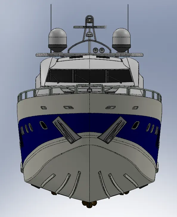
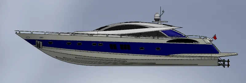
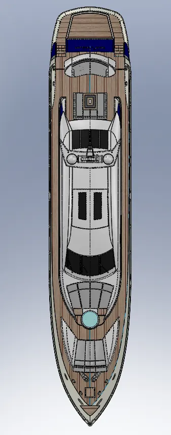
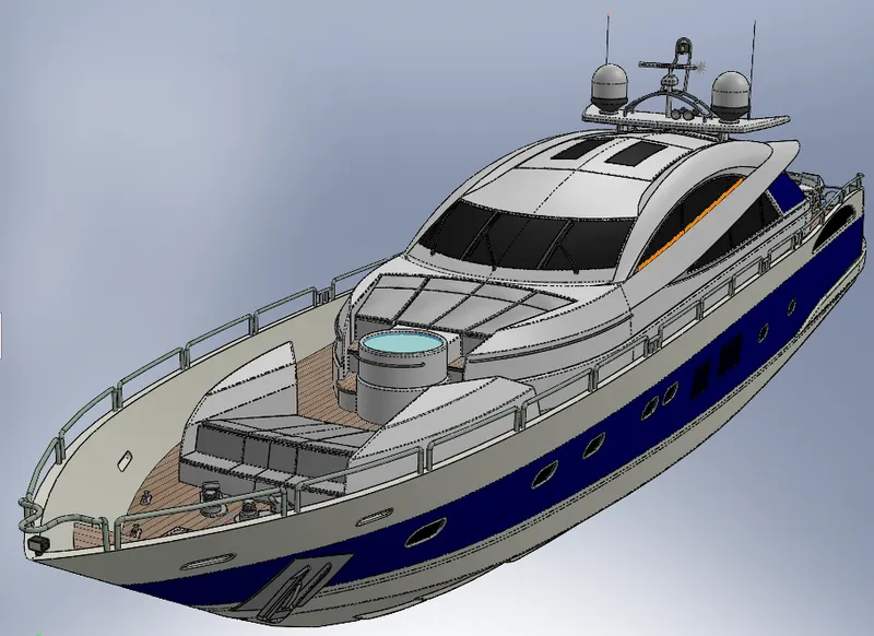
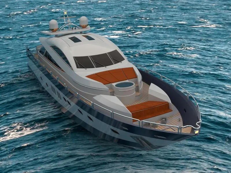
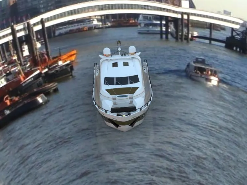
RENDERING : Rendering is done to get the realistic view of the modelled part.Here rendering is done using the SOLIDWORKS VISUALISE software.
CONCLUSION: Modelling the parts,assembling and rendering was successfully completed using the SOLIDWORKS software.