Photo Realistic Rendering
MODELLING OF AMERICAN CHOPPER USING SOLIDWORKS
OBJECTIVE: To model different parts of the american chopper,assembling it and also rendering it using the deisgn software SOLIDWORKS.
INTRODUCTION: American chopper is a type of custom motorcycle which emerged in California in the late 1950s. A chopper usually employs high steering angles,lengthened forks for a stretched-out appearance,lower seat heights,long wheelbase,hardtail frames (frames without rear suspension),low ground clearance and long front suspension travel.
DESIGN METHODOLOGY:
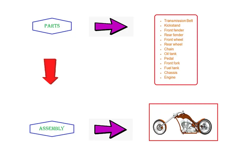
COMMANDS USED:
1.EXTRUDE BOSS/BASE:It is used in extruding the sketch profile in one or more direction to create a solid feature.
2.CUT EXTRUDE:It cuts a solid modelby extruding sketch profile in one or more direction.
3.REVOLVE:It is used in revolving the sketch profile around a particular axis to create a solid feature.
4.FILLET:It creates a round internal or external edges around the edges of the face.
5.CHAMFER:It creates an angle or distance edges around the edges of the face.
6.SWEEP:It helps in sweeping a closed profile along a closed or open path.
7.DOME:It is used to create a circular or elliptical face over a selected portion.
8.COMBINE:It is used to combine two or more bodies.
9.SPLIT:It is used to removal or trimming of part from the selected sketch
10.LINEAR AND CIRCULAR PATTERN:It is used to create circular or linear pattern of the selected sketch along the same path.
11.MIRROR:It mirrors a face or body about the selected mirror plane.
12.CURVE DRIVEN PATTERN:It creates a pattern of the selected sketch profile along a curve.
13.COMPOSITE CURVE:It is the combination of the two projected curves.
14.CUT REVOLVE:It cuts a solid model by revolving sketch profile around axis in one or two direction.
15.LOFT:It creates a shape by making transitions between multiple profiles and guide curves.
16.SHELL:It hollows out a part,leaves open the faces we select and creates thin walled features.
17.SURFACE TRIM:It trims or remove material from selected surface sketch.
18.SURFACE KNIT:Knits two or more bodies so that no gap is in between them and forms a solid model.
DESCRIPTION:
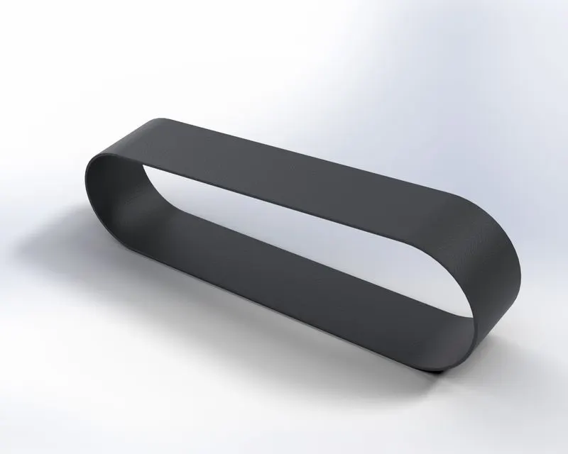
1.TRANSMISSION BELT:
TOOLS USED:
* 3-Point arc
* Line
* Offset Entity
FEATURES:
1.Boss extrude
2.Fillet
3.Apperarance
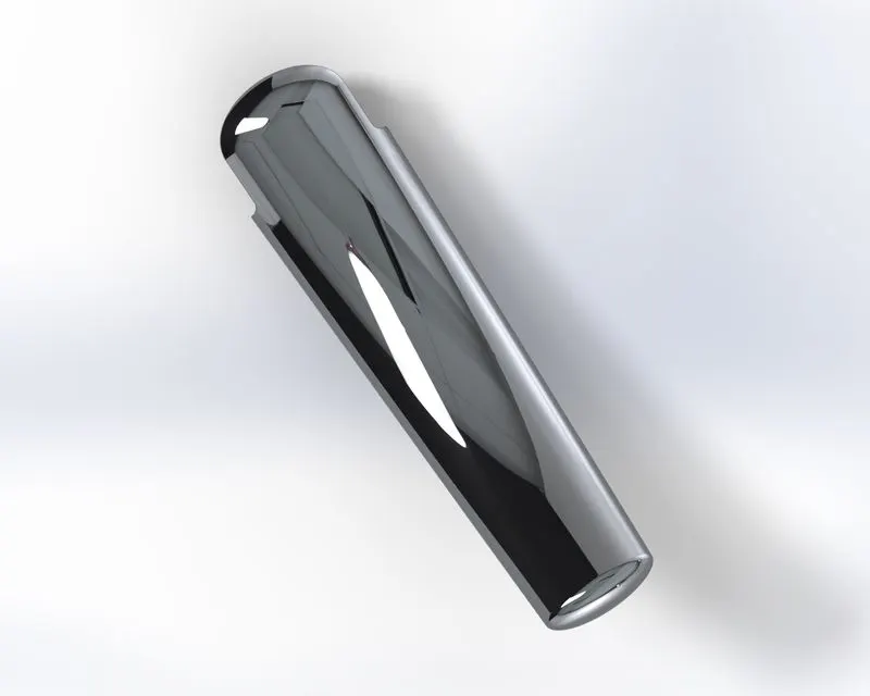
2.KICKSTAND:
TOOLS USED:
*Ellipse
*Spline
*Pierce
FEATURES:
1.Boss Extrude
2.Cut Extrude
3.Split
4.Dome
5.Loft
6.Fillet
7.Appearance
3.FRONT FENDER:
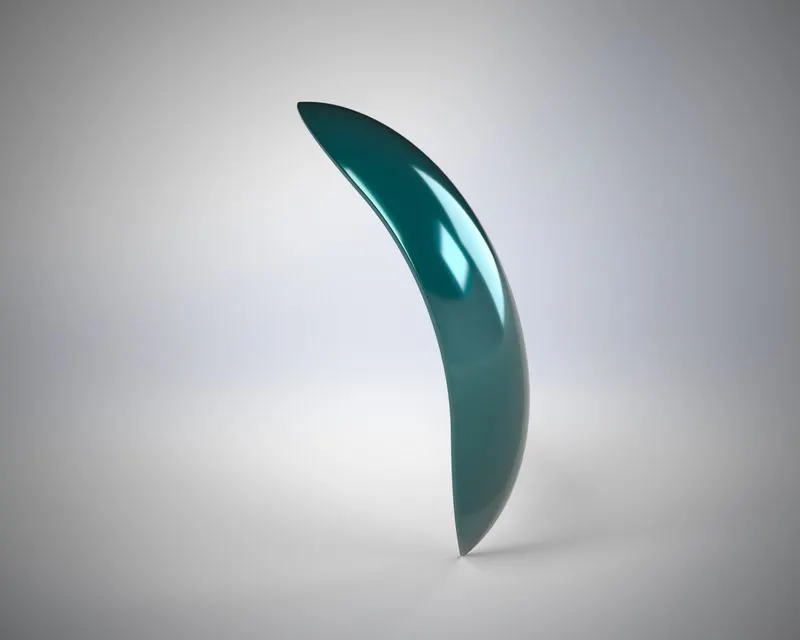
TOOLS USED:
*3-Point arc
*Offset Entity
*Line
*Spline
FEATURES:
1.Revolve
2.Split
3.Dynamic mirror entity
4.Fillet
5.Appearance
4.REAR FENDER:
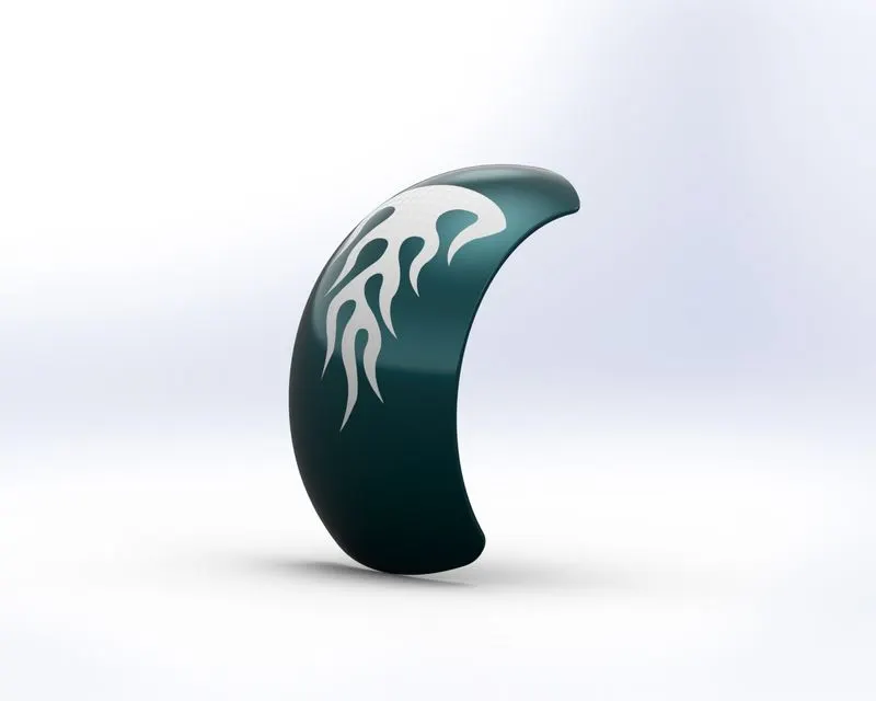
TOOLS USED:
*3-Point arc
*Offset entity
*Spline
*Line
FEATURES:
1.Revolve
2.Split
3.Shell
4.Dynamic mirror entity
5.Fillet
6.Appearance
5.FRONT WHEEL:
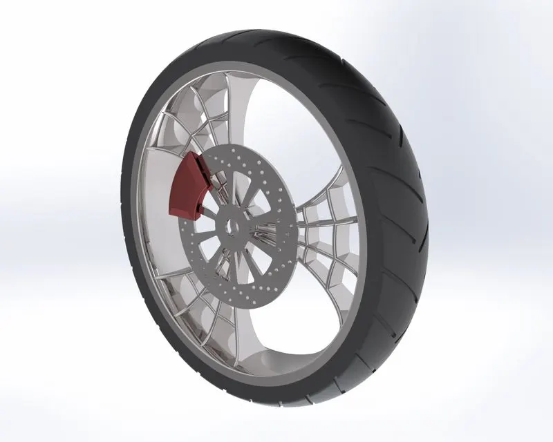
TOOLS USED:
*3-Point arc
*Line
*Spline
*Midpoint line
*Sketch fillet
*Circle
*Trim
*Extend
*3-point center rectangles
FEATURES:
1.Extrude boss/base
2.Revolve boss/base
3.Combine
4.Extrude cut
5.Revolve cut
6.Circular pattern
7.Fillet
8.Chamfer
9.Appearance
6.REAR WHEEL:
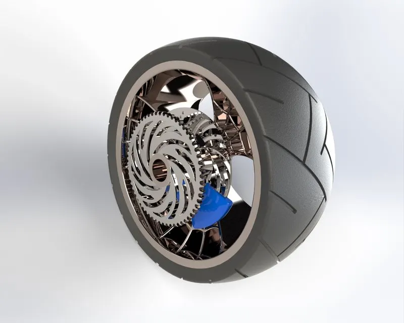
TOOLS USED:
*3-point arc
*Line
*Spline
*Midpoint line
*Circle
*Sketch fillet
*Trim
*Extend
*3-point center rectangle
FEATURES:
1.Extrude boss/base
2.Revolve boss/base
3.Combine
4.Extrude cut
5.Revolve cut
6.Circular pattern
7.Fillet
8.Chamfer
9.Appearance
7.CHAIN:
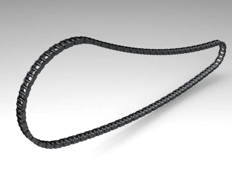
TOOLS USED:
*3-Point arc
*Centerpoint slots
*Circle
FEATURES:
1.Extruded boss
2.Make and save block
3.Curve driven pattern
4.Fillet
5.Mirror
6.Appearance
8.OIL TANK:
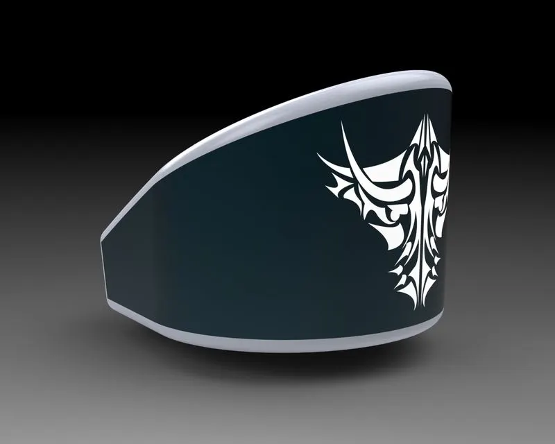
TOOLS USED:
*3-Point arc
*Line
FEATURES:
1.Extruded boss/base
2.Fillet
3.Combine
4.Shell
5.Appearance
9.PEDAL:
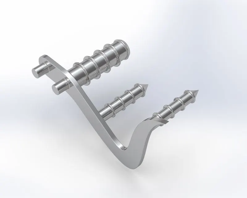
TOOLS USED:
*3-point arc
*Spline
*Circle
*Line
*Sketch fillet
FEATURES:
1.Extruded boss
2.Revolve
3.Fillet
4.Dome
5.Chamfer
6.Linear pattern
7.Appearance
10.FRONT FORK:
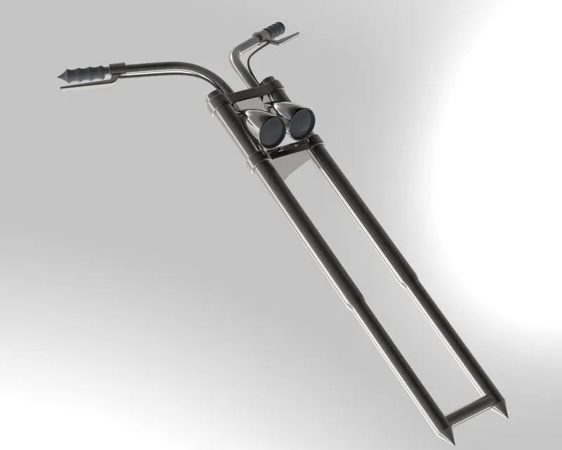
TOOLS USED:
*3-point arc
*Line
*Spline
*Circle
*Trim
FEATURES:
1.Extrude boss/base
2.Revolve boss/base
3.Linear pattern
4.Extrude cut
5.Revolve cut
6.Dome
7.Body move/copy
8.Curves projected
9.Sweep
10.Reference geometry-planes
11.Mirror
12.Combine
13.Fillet
14.Chamfer
15.Appearance
11.FUEL TANK:
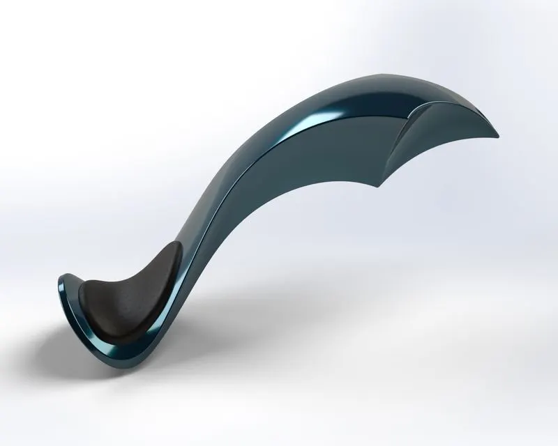
TOOLS USED:
*Line
*Spline
*Construction line
*Trim
*Extend
FEATURES:
1.Surface sweep
2.Surface loft
3.Surface trim
4.Surface knit
5.Boundary surface
6.Surface extrude
7.Curves
8.Projected curves
9.Split line
10.Sweep cut
11.Reference geometry-planes
12.Mirror
13.Shell
14.Fillet
15.Appearance
12.CHASSIS:
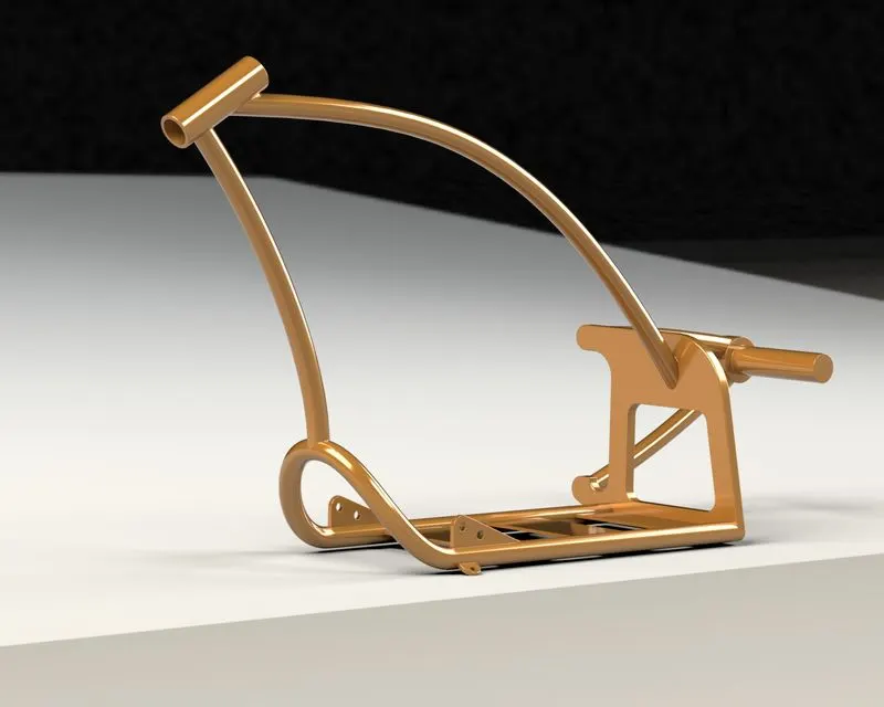
TOOLS USED:
*Sketch picture
*Line
*Spline
*Circle
*Trim
FEATURES:
1.Extrude boss/base
2.Extrude cut
3.Revolve
4.Dome
5.Curves-projected
6.Sweep
7.Split
8.Reference geometry-planes
9.Mirror
10.Combine
11.Fillet
12.Chamfer
13.Appearance
13.ENGINE:
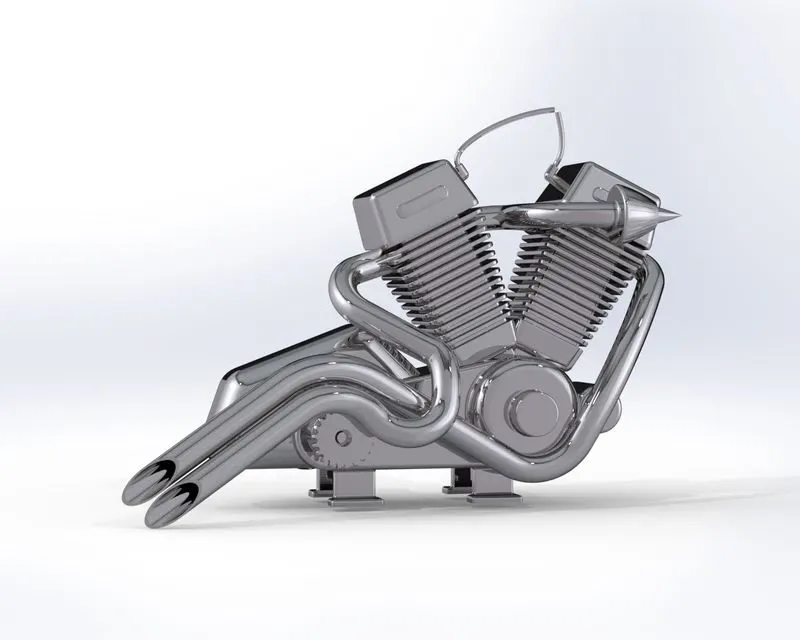
TOOLS USED:
*Sketch picture
*Line
*Spline
*Circle
*Circular sketch pattern
*Construction line
*Centre point rectangle
*3-point centre rectangle
*Trim
FEATURES:
1.Extrude boss/base
2.Extrude cut
3.Revolve
4.Dome
5.Curves-projected
6.Sweep
7.Split
8.Reference geometry-planes
9.Mirror
10.Combine
11.Fillet
12.Chamfer
13.Appearance
14.Composite curves
15.Circular pattern
16.Linear pattern
ASSEMBLY: Basically the process of assembling the parts can be done in two ways:
*Top-down method
*Bottom-up method
The method I used here is bottom-up method which is we first design and model the parts,and then insert into an assembly and use mates to position the parts.
'MATES' in the solidworks software is of 3 types which includes standard mates, advance mates and mechanical mates.In this model we mainly used the standard mates and advanced mates which consists of concentric,coinicident,parallel,perpendicular,tangent,symmetric,path,width,linear,angle and distance mates.
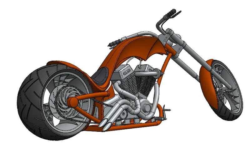
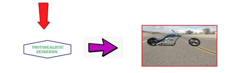
PHOTOREALISTIC RENDERING:
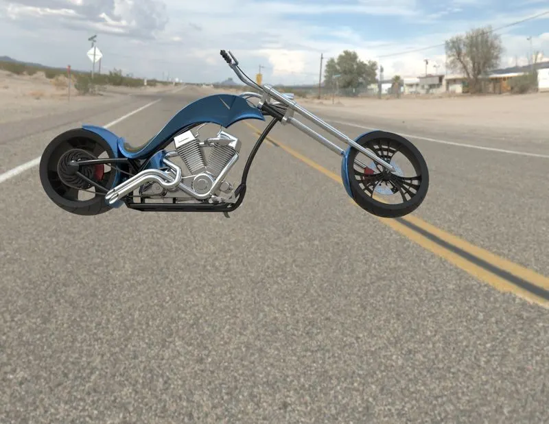
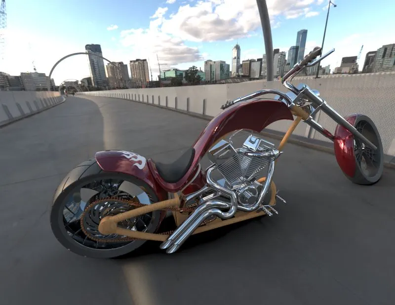
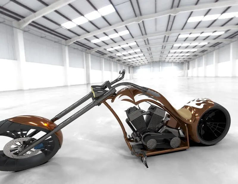
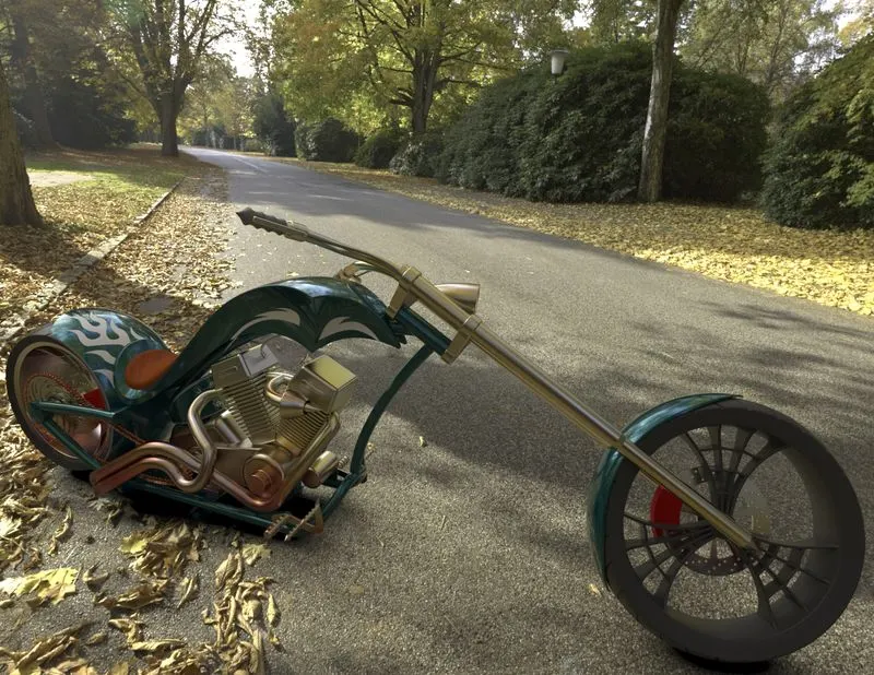
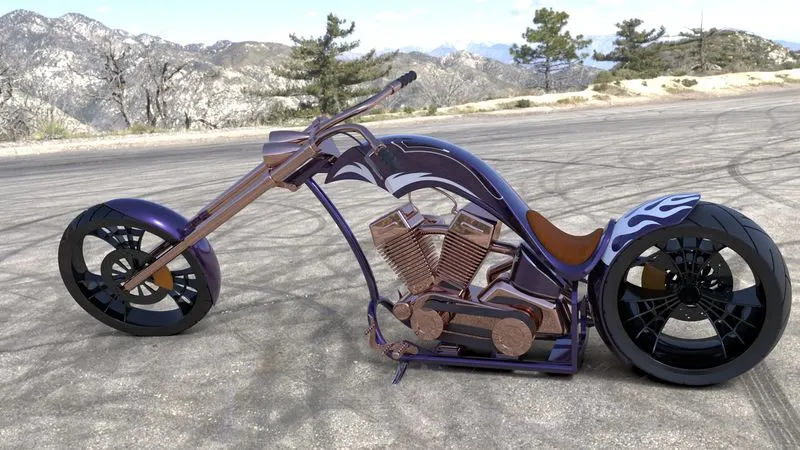
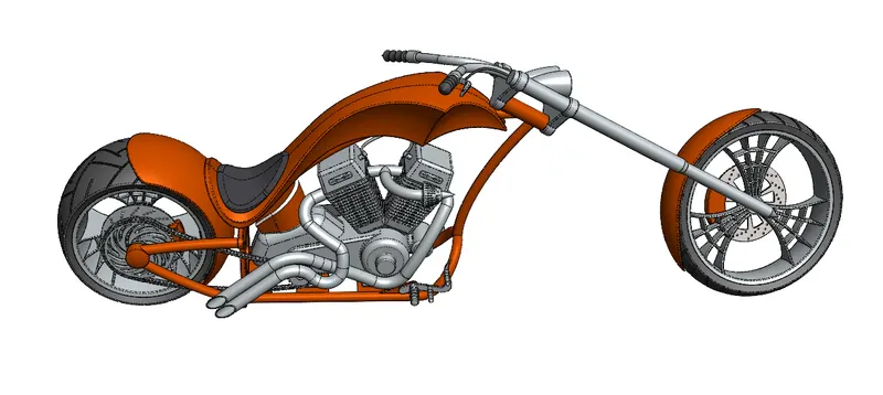
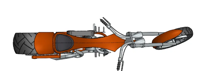
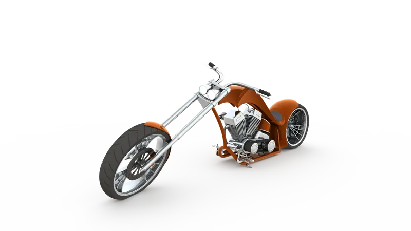
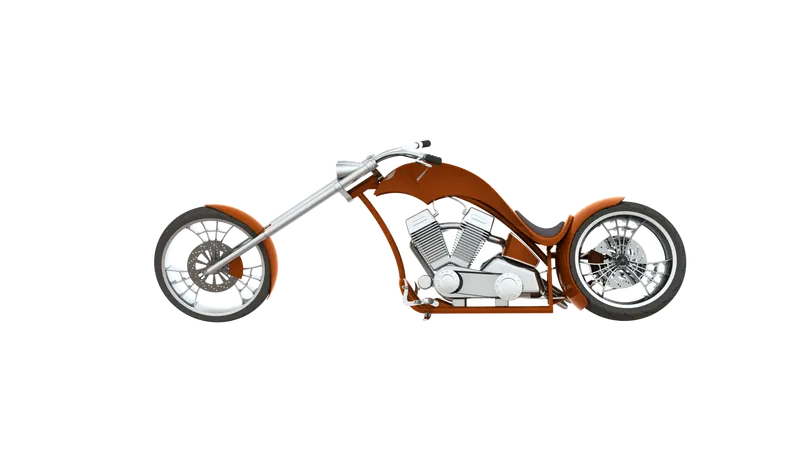
SOLIDWORKS VISUALISE: The above images are rendered using the solidworks visualise software,making the american chopper more realistic.
CONCLUSION: Modelling the parts,assembling and rendering was successfully completed using the solidworks software.