Radar Mast & Final Assembly of Yacht
YACHT ASSEMBLY REPORT
Objective:
- To design, assembly and render all the individual parts of the yacht model by using the design tool - Ultimate Solidworks.
- By the usage of sketch tools with fully defined importance of mates in assembly.
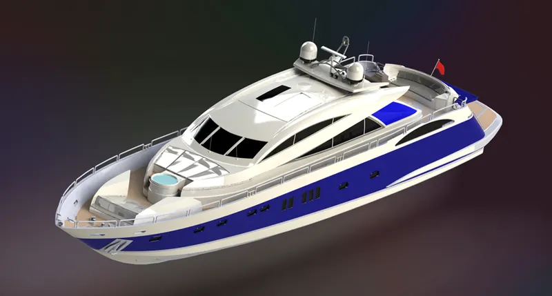
- To render the yacht model by usage of rendering tool in Photo view 360 method.
- The main purpose of project is to understand all commands and create a full yacht with all its component and bring it realistic as possible.
Software Used:
- Solidworks – 2020
Introduction;
- Solidworks: is a solid modelling computer-aided design (CAD) and computer-aided engineering (CAE) program published by Dassault Systems
- Solidworks has three major environments namely:
- Part
- Assembly
- Drawing
- Part – modelling is a 3D solid modelling in Solidworks with Parametric modelling and feature based approach simultaneously wherein parameters determine the shape and geometry of the solid model, converting 2D sketches into 3D models requires the feature-based approaches
- Assembly-In this environment the various parts can be Mates to each other. Mates are categorized into general, Advanced and mechanical mates. The constraints between two parts such as Concentric, Parallel, Coincidence and Tangency
- Drawing-It is mainly used to create 2D sheets with all main views of the solid parts and assembly. This sheet details and information is used for manufacturing of the component such as geometric dimensions, tolerance and section views for required part and assembly.
- In the Solidworks software the file formats for modeling
- Parts- (. SLDPRT)
- Assembly- (. SLDASM)
- Drawing- (. SLDDRW)
DESIGN METHODOLOGY:
MODELLING OF YACHT:
- Yacht modelling completely depends on surface modeling.
- In this modelling the most important part to set up the blueprint for as per the requirement of parts in blueprint do the process to get the desired part.
COMPONENT OF YACHT MODELING:
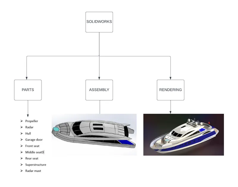
- Propeller
- Radar
- Hull
- Garage door
- Front seat
- Middle seatD
- Rear seat
- Superstructure
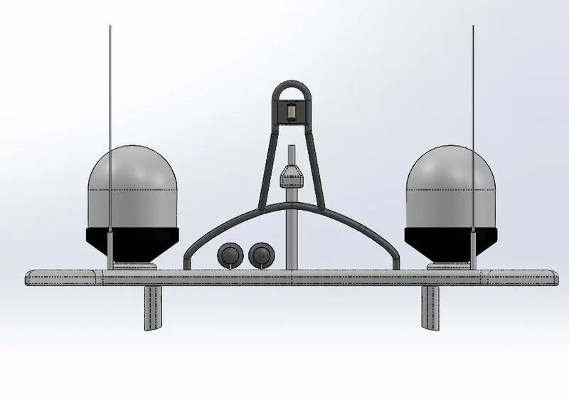
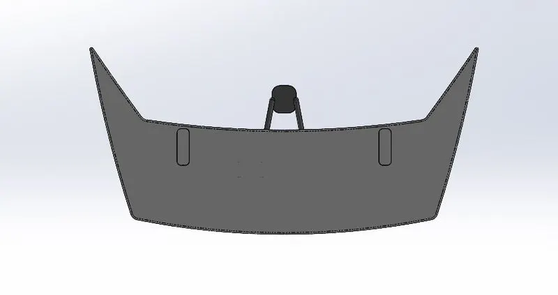
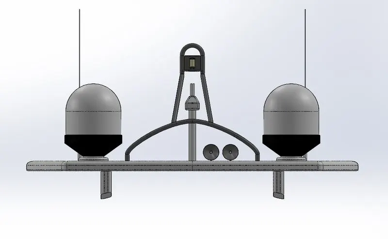
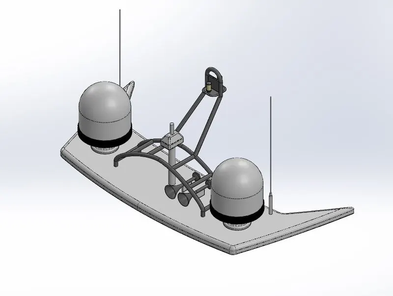
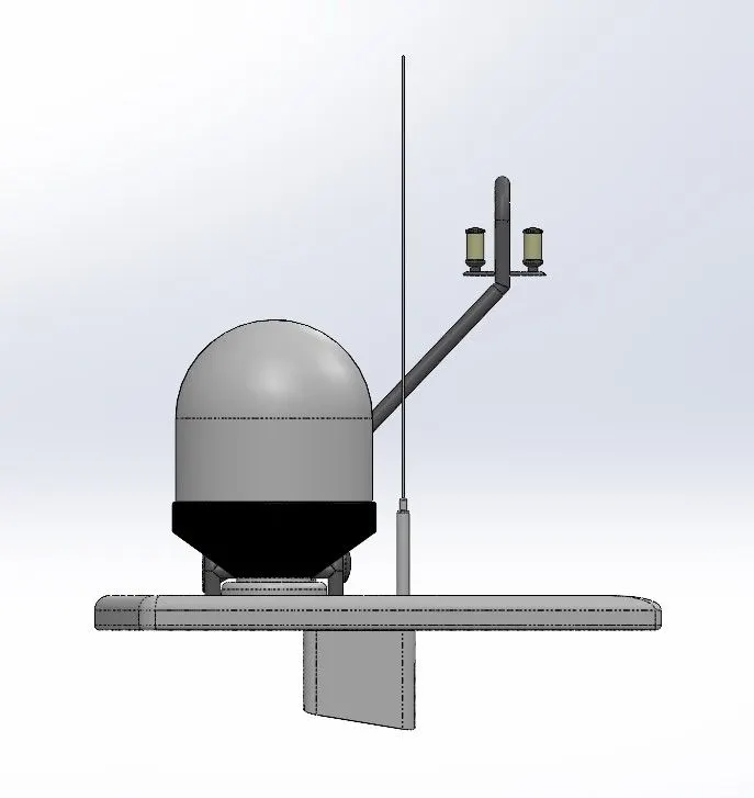
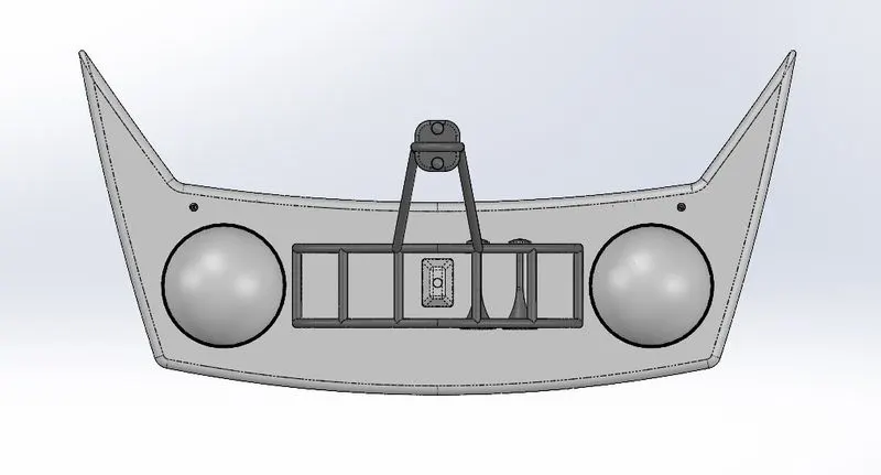
- Radar mast
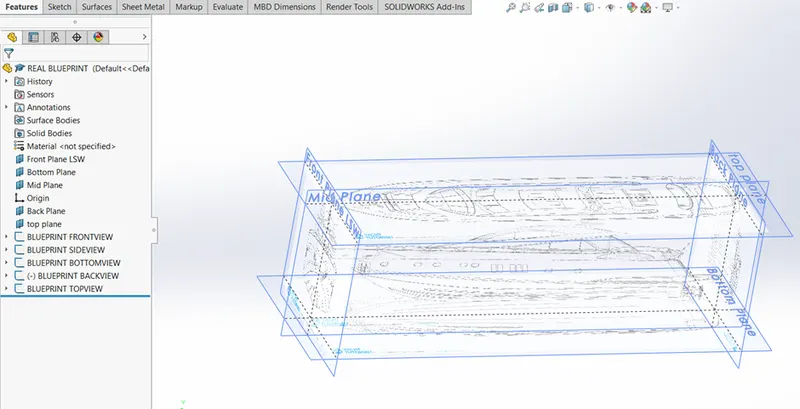
1.BLUEPRINT SETUP OF YACHT MODELLING:
- The blueprint setup plays an important role in yacht modelling. for as per the reference of 2D sketch and requirement of parts in blueprint do the process to get the desired part.
- Following steps need to get the setup;
- Tools > sketch tools > sketch picture > browser.
- Browser the picture location file and click on ok. Then give properties data to get the exact setup for modelling.
2.PROPELLER:
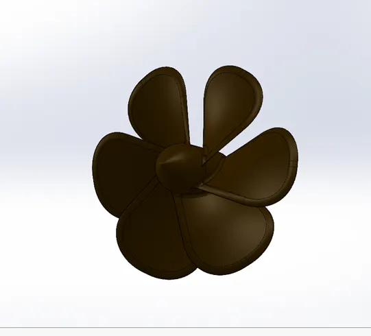
- Propeller is used to create the force that move a boat forward and backward.
- Its rotary motion through the air creates a difference in the pressure between the front and back surfaces of its blades. It provides thrust so that the yacht moves easily.
TOOLS FEATURES USED FOR MODELLING:
- Line
- Spline
- 3-point corner rectangle
- Revolve
- Reference geometry
- Loft
- Fillet
- Cut extrude
- Pattern/mirror
- appearance
PROCEDURE FOR MODELLING:
- Open a new part with model units set to millimetres
- Select the right plane in the feature manager and make a new 2Dsketch
- Draw a three straight line and spline as shown in figure and add the relation tangency between the line and the spline.
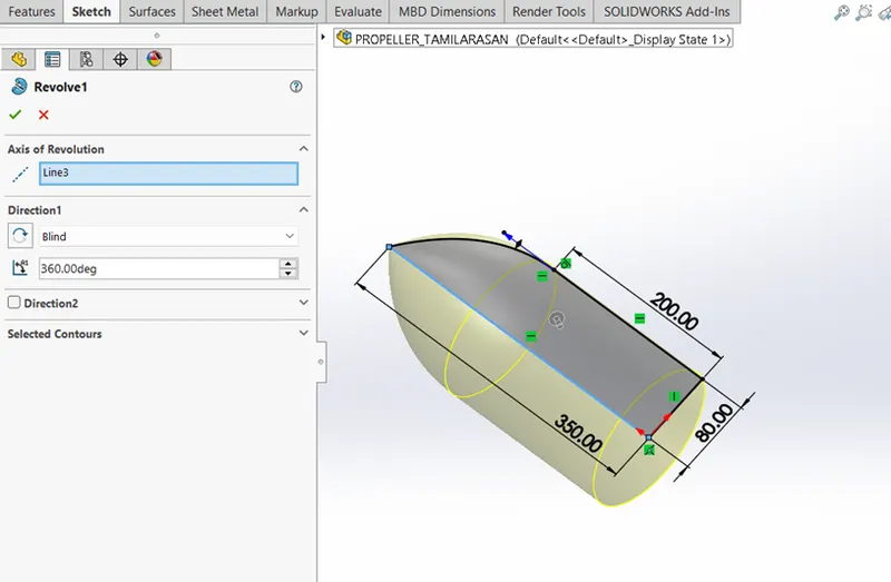
- Create a revolve in axis of revolution in direction 1 blind about the 360 degrees .as shown in picture.
- Select the top plane to create a new sketch by using the 3-point corner rectangle and give the dimension of the rectangle
- Create a new plane by using the reference geometry and make anew sketch in plane 1 as shown in the figure.
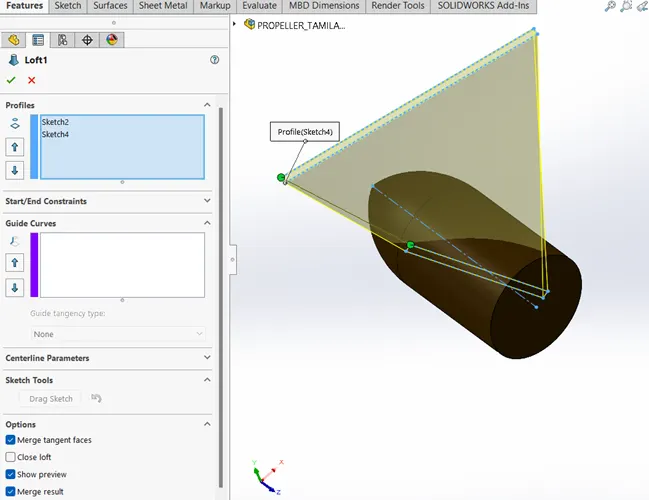
- Use the boss/base > loft feature to create a profile of propeller blade and fillet the edges of blade.
- Create a circular pattern for number of instance 6 blades and select the equal spacing option.
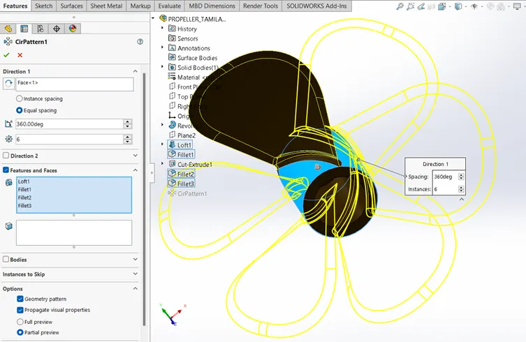
- Change the colour of the propeller by using appearance option.
3.RADAR:
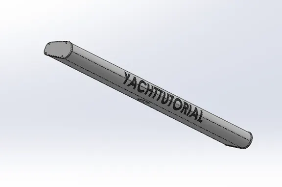
- Radar is used for navigation purpose and helps the detecting safety signals of weather system, near landmasses and boats.
TOOLS FEATURES USED FOR MODELLING:
- Line
- circle
- boss Extrude
- Cut extrude
- Fillet
- Offset entities
- Sketch entities > polygon
- Pattern/mirror
- Text entities
- Appearance
PROCEDURES FOR MODELLING:
- Open a new part with model units set to millimetres.
- Select the right plane in the feature manager and make a new 2Dsketch.
- Draw a four straight line and spline as shown in figure and add the dimensions & relation.
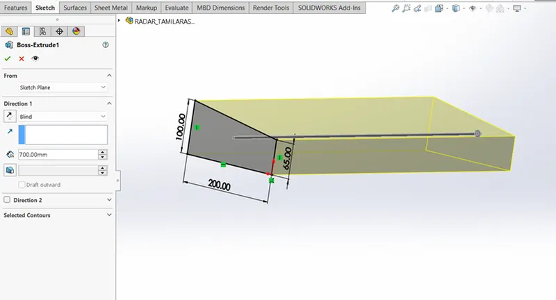
- Create a extrude and change the depth to 700mm, then fillet the two edges of the model.
- Draw a new sketch in the selected blue surface by using offset entities features in outwards direction.
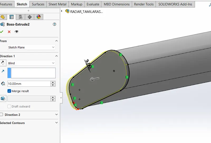
- Create an extrude on the offset surface and change the depth to 10mm. as shown in figure.
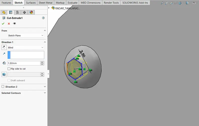
- Draw a circle and add the dimension, then create a extrude in the circle and draw the sketch entities > polygon, then create a cut extrude as shown in figure.
- Mirror the radar by selecting the right plane and select the bodies to mirror option, then enable merge solids option.
- Draw a circle in the bottom centre of the radar and create a cut extrude as shown in figure.
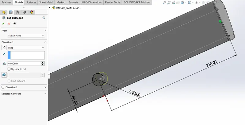
- Finally add the text using sketch entities > text and give a white colour to radar by using appearance feature.
4.HULL:
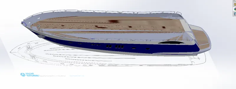
- A hull is the watertight body enclosure of the ship or boat
- The hull may open at the top or it may be fully or partially covered with superstructure which can protects the goods carrying area, machinery and accommodation spaces of the ship from the weather, flooding and structural damage.
TOOLS FEATURES USED FOR MODELLING:
- Line
- Circle
- Spline
- Convert entities
- Offset entities
- Boss/base – extrude, revolve and sweep
- Cut Extrude
- Fillet
- Trim
- Chamber
- Reference geometry
- Linear pattern/mirror
- Surface features
- Appearances
PROCEDURES FOR MODELLING:
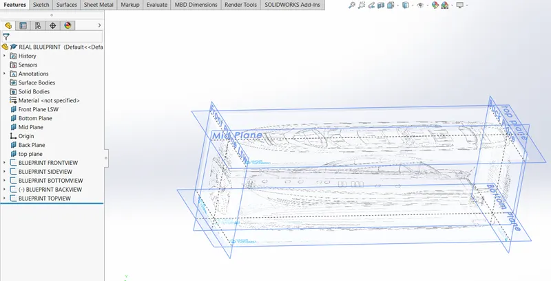
- Open the blueprint setup file and rename as hull and save the file, then open the hull file with blueprint setup
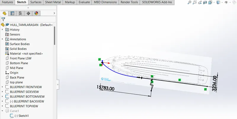
- Select the bottom plane for create a new sketch and draw a bottom structure of hull with the help of blueprint reference picture by using the feature tools like line, spline and create a projected curve as shown in figure
- Create a surface loft by using the fully defined curve1 and curve 2, then make sure the green balls on the same end as shown in figure.
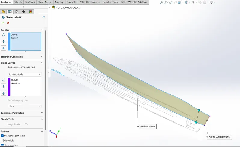
- Create a new sketch on the mid plane and back plane which can create bottom surface loft of the hull model as shown in figure.
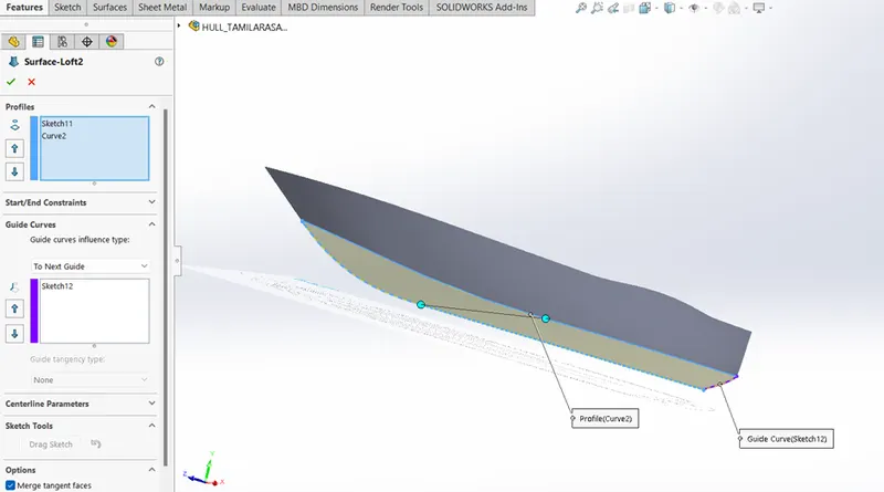
- Then trim the rear of surface – loft 1 and surface – loft 2 by selecting the purple surface next to the cutline as shown in figure.
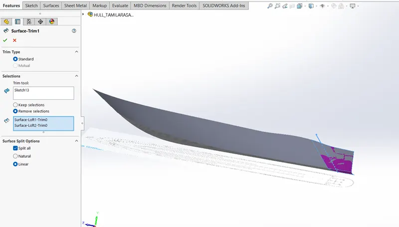
- Make a new sketch in mid plane using line and spline features put the arrow to approach the curve on the blueprint as good as possible.
- Create surface loft by selecting the edges and sketch as shown in the figure with tangency to face and normal to profile.
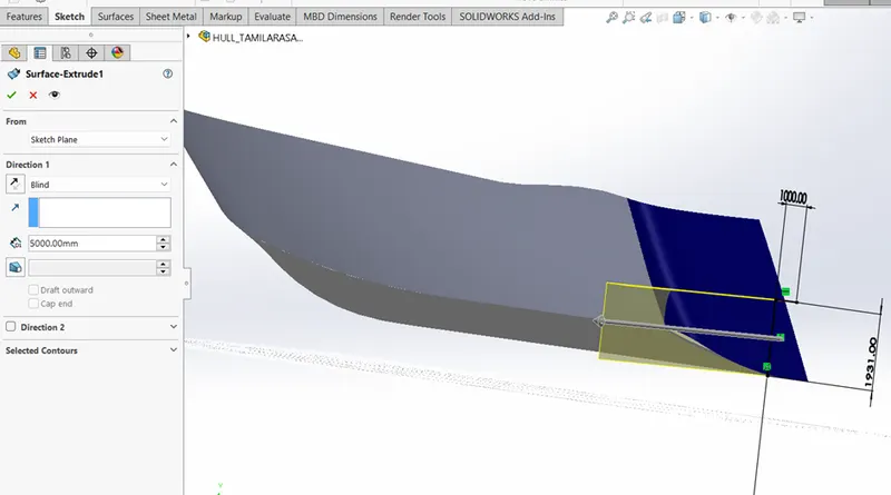
- Trim the rear of surface loft 1 and surface loft 2 by selecting the purple surface and select the surface split option: linear.
- Knit the surface of the hull by click in the selection box and select the 3 blue surfaces and select the “gap control” option.
- Create a surface fill by selecting the new sketch draw in a mid-plane and three blue edges as shown in figure.
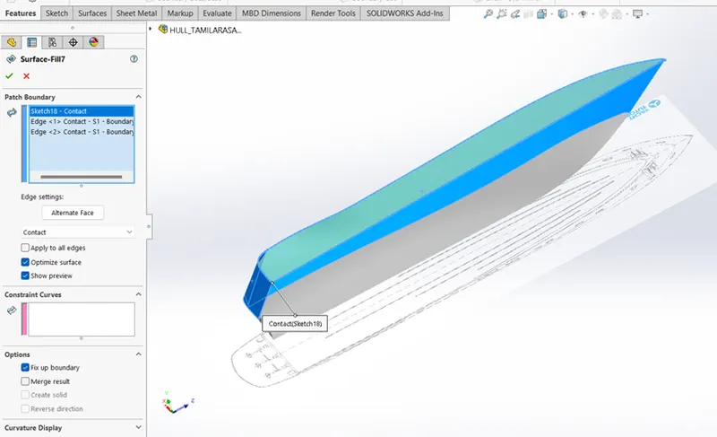
- Selecting the two blue surface to create a shell feature and change the diameter 1- 120mm then click ok for the thickness warning.
- Create a fillet and chamfer for the model to give perfect surface finishing and create linear pattern for the other windows by selecting the four line and fillet to the corners of the rectangle as shown in figure.
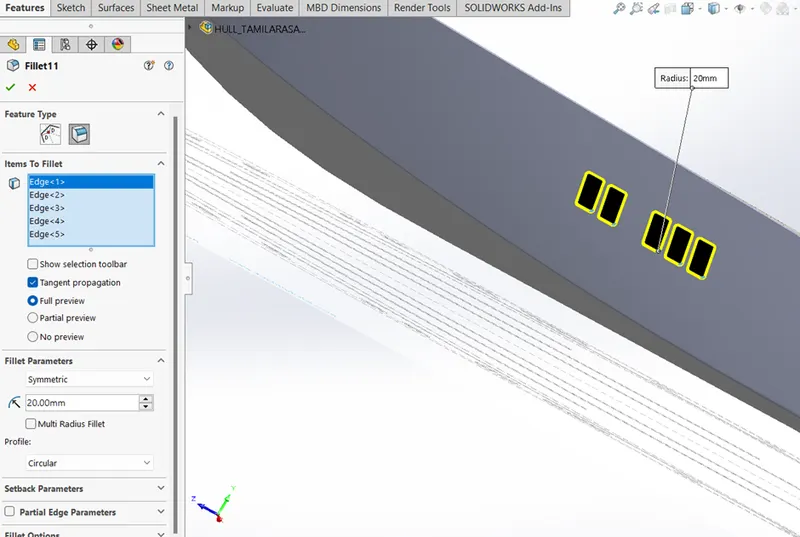
- Then create a cut extrude and offset from the surface to outward direction, then create a solid sweep for the portholes and repeat it for other 6 portholes.
- By using the top view of blue print create a step by using the sketch entities like line and spline. Then use cut extrude and boss extrude to complete the steps structure on the hull.as shown in figure.
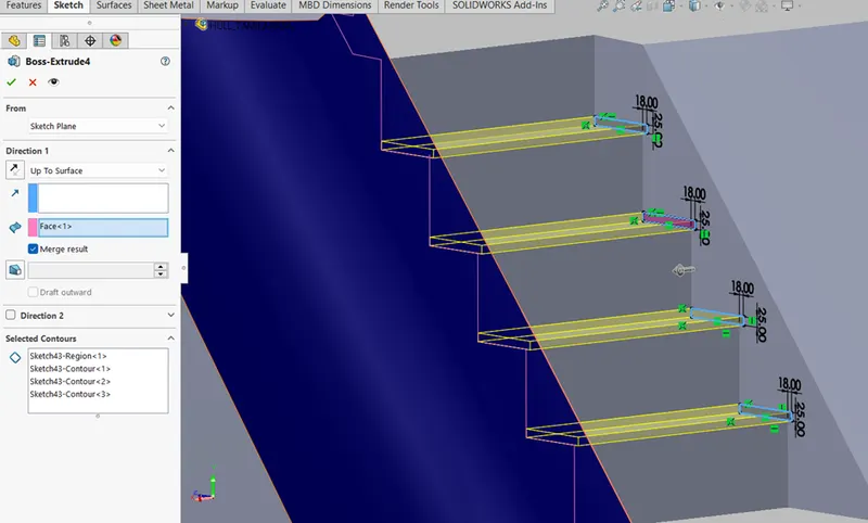
- Create a new plane from the bottom plane to draw hull bottom surface by using spline and offset entities, then boss extrude then offset from the surface and fillet the lines
- Create a new plane from draw steps hand holder pipes by using the sketch entities like line, rectangle, arc and circle then create a solid sweep by using circle path and profile and also create sketch for safety guard pipes on the edges of the hull as shown in figure.
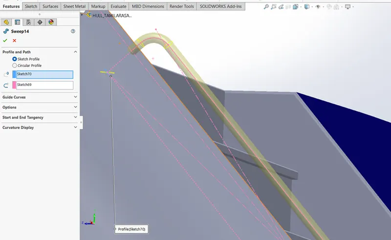
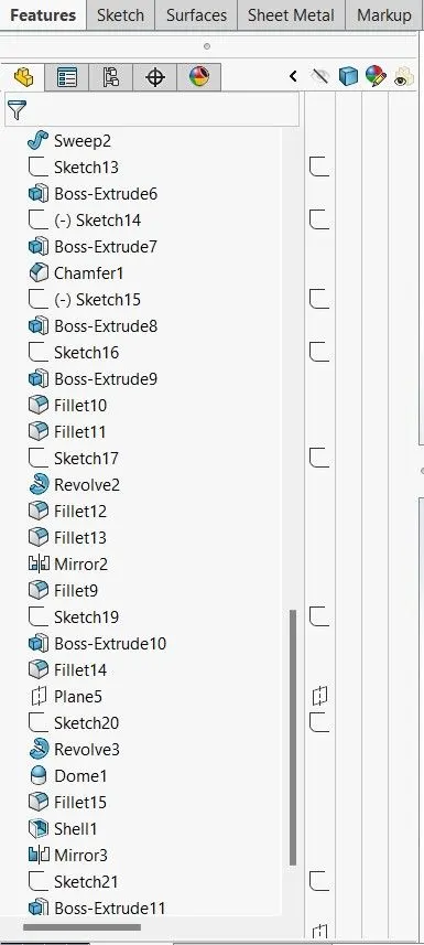
- Unhide the blueprint sideview and create a new sketch on the midplane for the propeller engine by reference picture of blueprint, then create a revolve about an axis of revolution select the blue line as shown in the figure.
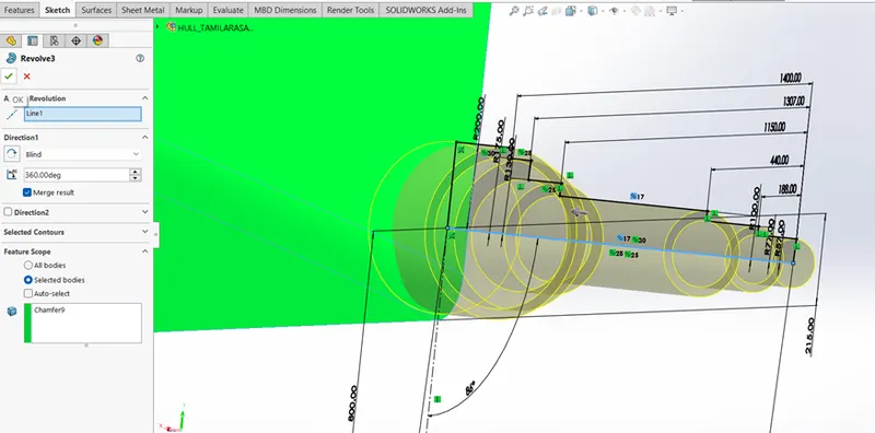
- Create a linear pattern to mirror the propeller engine rotation shaft and change the number of instances to 2 and select the features in the features tree for feature to pattern box.
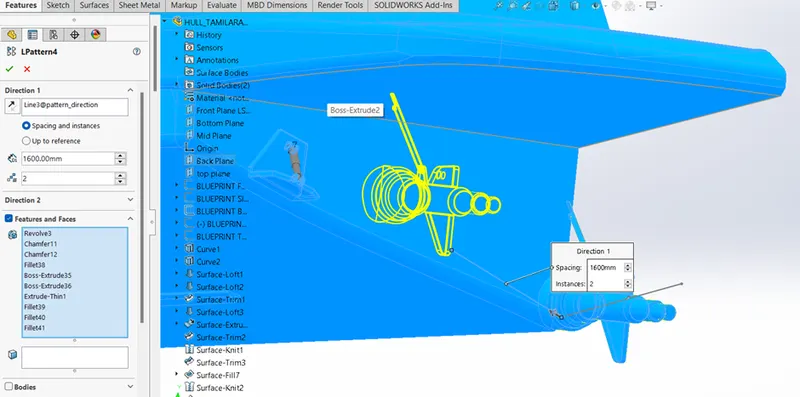
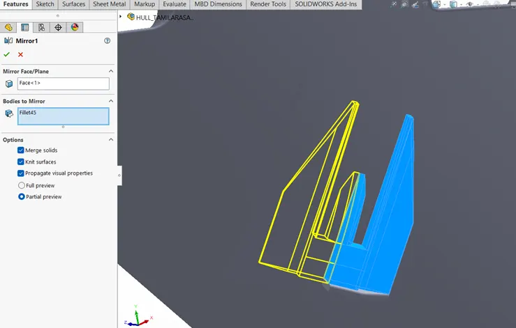
- Draw a anchor in a created plane with sketch entities and surface extrude in pointed outwards, then chamfer the edges of the half sketched anchor and mirror the anchor by using pattern/mirror feature.
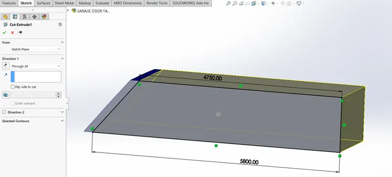
- Select the mid plane to create garage door sketch and cut extrude the part to save separated solid body for modelling garage door of yacht model.
- Create and change the colour of each part of hull by using the appearance features.
- Create a teak deck by enable photo view 360 as shown in the picture and edit decal the main floor and stair steps.
5.GARAGE DOOR:
- In yacht modelling the garage door is used for store the materials, items and others etc…
- It provides safety from bad weather, moisture etc...
TOOLS FEATURES USED FOR MODELLING:
- Line
- Circle
- Cut extrude
- Fillet
- Sketch tool > text
- Reference geometry
- Appearance
PROCEDURE FOR MODELLING:
- Open the exported body of the hull part model to create a garage door for yacht.
- Select the right plane to create a sketch by using line and add the dimension, then cut > extrude in trough all direction as shown in the figure.
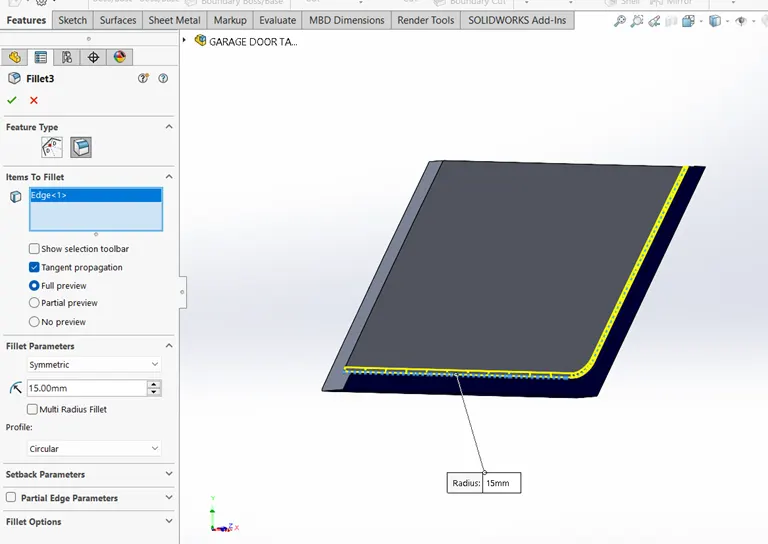
- Create a shell on the back side of the garage door and fillet the edges as shown in the figure.
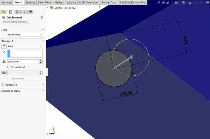
- Make a new sketch on the side face of the garage door for holding rode gape by draw a circle and create a cut > extrude as shown in the figure.
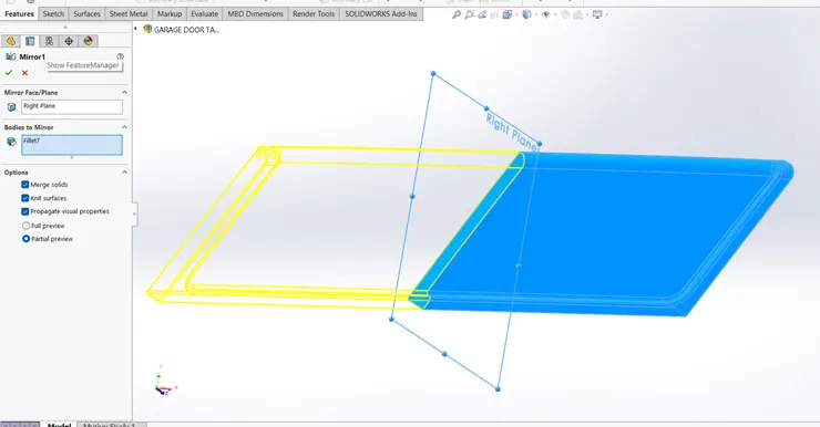
- Mirror the garage door by using pattern/mirror > mirror, then select the right plane and select the bodies to mirror option and also select the merge solids, knit surface option.
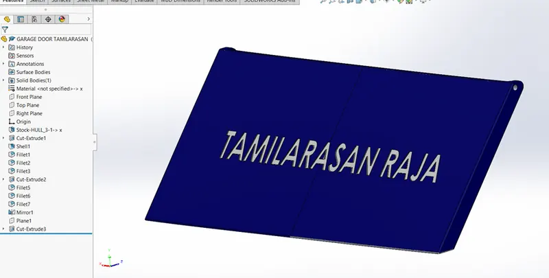
- Create a new plane by reference geometry to sketch the text entities and create a cut > extrude text profile in front faced of the garage door and add appearance to the garage door.
6.FRONT SEAT OF YACTH:
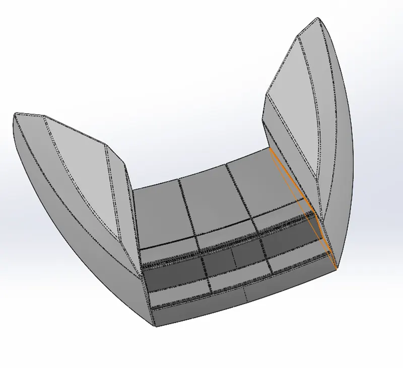
- Seat is used for the purpose of rest; it is also an important part of the superstructure. Of the yacht.
- In front seat of yacht accommodated with two persons in the modelling.
TOOLS FEATURES USED FOR MODELLING:
- Line
- Spline
- Boss > extrude
- Cut > extrude
- Surface > sweep
- Surface > loft
- Surface > trim
- Surface > knit
- Fillet
- Chamfer
- Reference geometry
- Appearance
PROCEDURE FOR MODELLING:
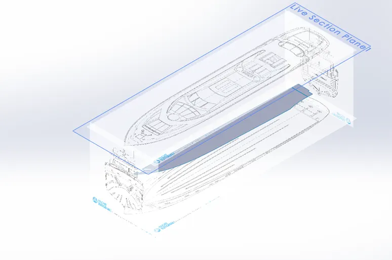
- Open the blue print setup and save the file as front seat and go to part features open the hull part uncheck all the option except the surface bodies option.
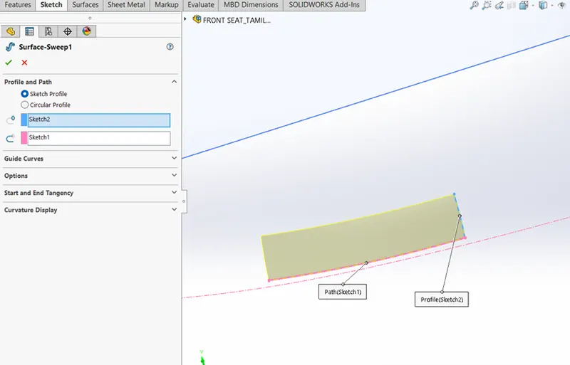
- Select the surface body top face and start sketch with the use of spline and add the dimension, then create a new plane on the sketch reference and sketch on the new plane to surface > sweep the drawn sketch as shown in figure.
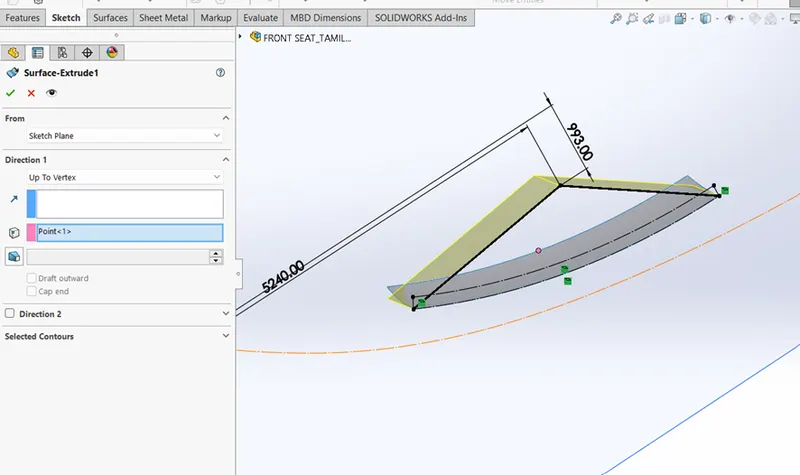
- Create a new sketch by switch the top view blueprint and draw a spline as shown in the blueprint pull at the arrow of the spline to match the curve of the blueprint and add the dimension.
- Create a new sketch by select the mid plane to draw a line and surface trim the new sketch line remove selected purple surface and create a surface > loft by click the profile box then select the two blue edges as loft profiles as shown in figure.
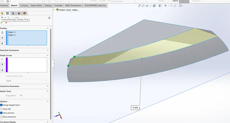
- Hide the deck surface and fill the underside of the body by using surface > fill icon and select the three edges of the body and select the optimize surface option as shown in the picture
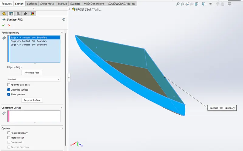
.
- Create a new sketch in select side and draw a line and add the dimension then convert the light blue curve for create a fully defined sketch to create a boss > revolve by selecting the axis of revolution – vertical line as shown in figure.
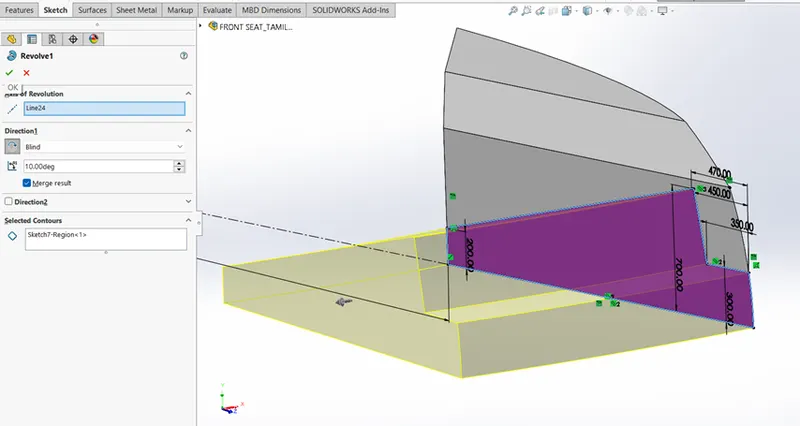
- Select the blue surface to create a new sketch by using offset entities and draw the two diagonal lines then add the dimensions and trim the line between the two diagonal lines as shown in figure.
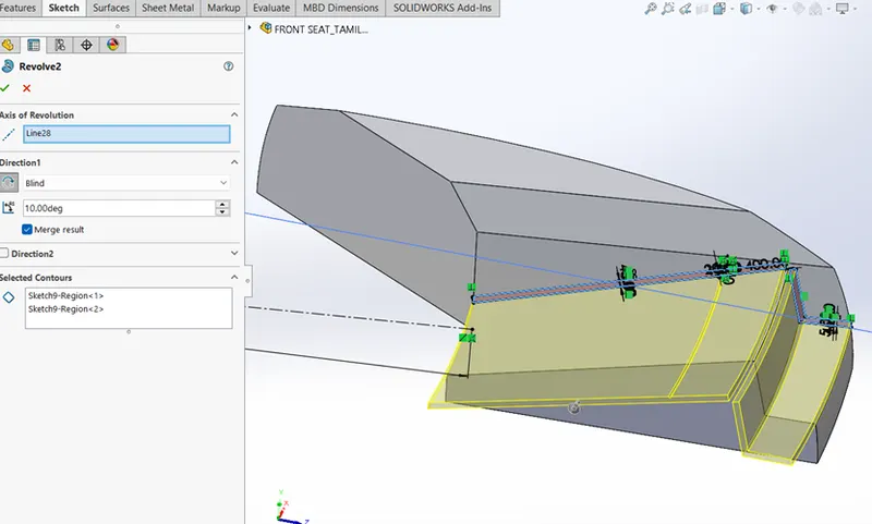
- Draw the two centrelines and add the dimension for them to create a boss > revolve and also extrude cut in the distance of 6000 mm make sure that the offset is directed downwards
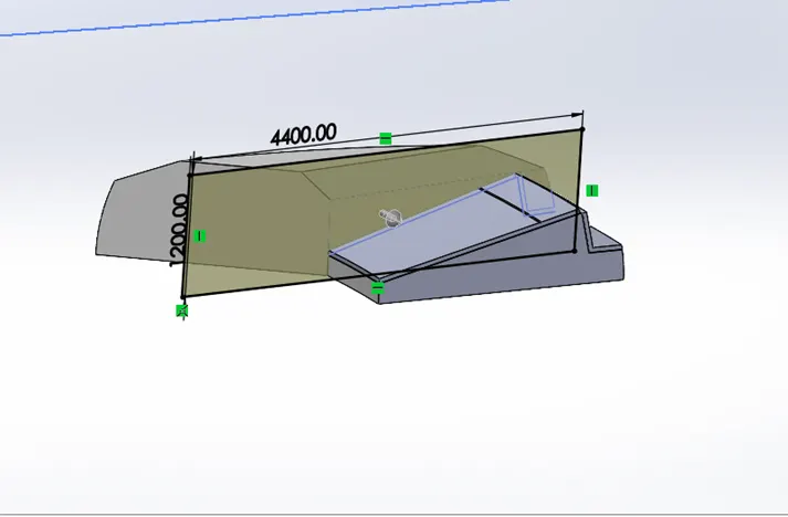
- Create a new sketch on the top plane by using line connected the ends of the line with the edges of the matrasses and add the dimensions, then create a extrude cut with enable thin features option, change direction up to body and select the pink body as solid body , then fillet the edges
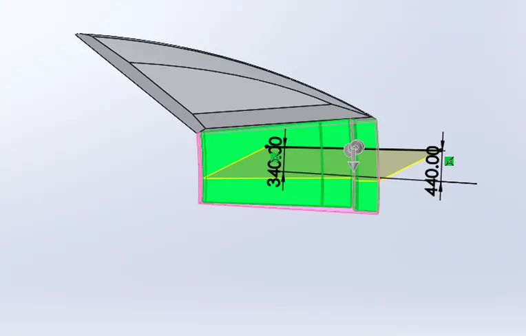 .
.- Mirror the side body of the front seat by selecting the mid plane and select the bodies to mirror as shown in figure.
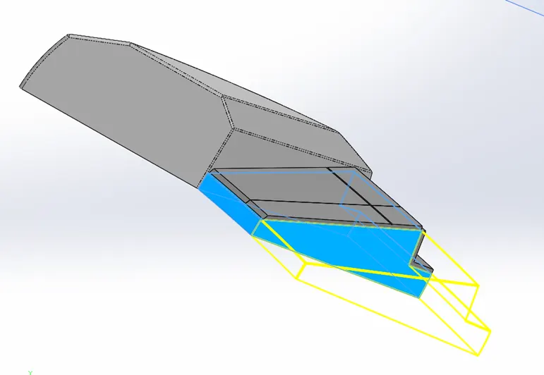
- Create dome on the selected blue surface body and make sure that the dome is directed upwards and set the dome.
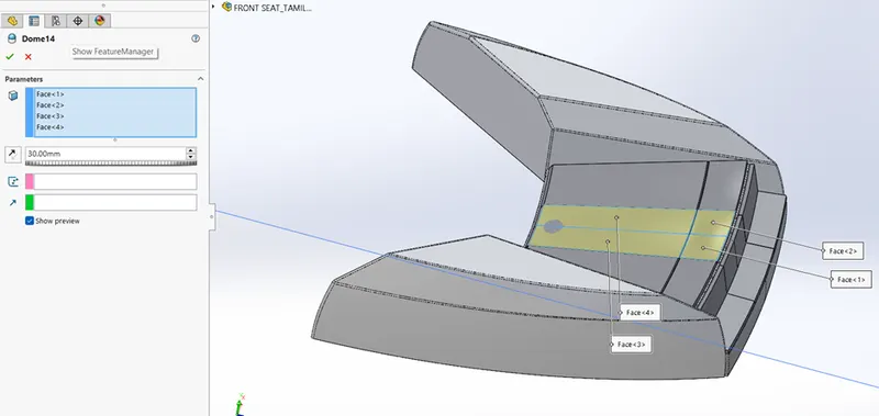
- distance to 30mm, then also do the same process for other two dome surface. And apply fillet features of the front seat.
- Finally apply the colour by using the appearance feature change the colours of main bodies and mattress bodies.
7.MIDDLE SEAT OF YACTH MODEL:
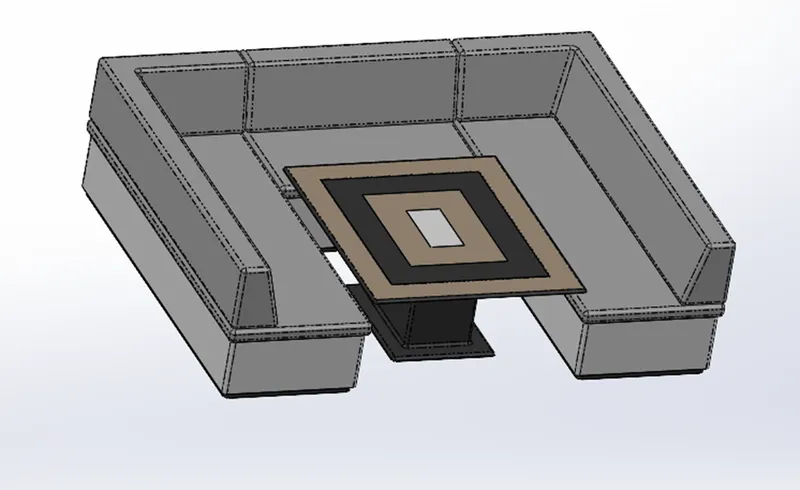
- Seat is used for the purpose of rest; it is also an important part of the superstructure. Of the yacht.
- In middle seat of yacht accommodated with three persons in the modelling.
TOOLS FEATURES USED FOR MODELLING:
- Line
- Spline
- Boss > extrude
- Cut > extrude
- Surface > sweep
- Surface > loft
- Surface > trim
- Surface > knit
- Fillet
- Chamfer
- Reference geometry
- Appearances
PROCDEDURE FOR MODELLING:
- Open the blue print setup and save the file as middle seat and go to part features open the hull part uncheck all the option except the surface bodies option.
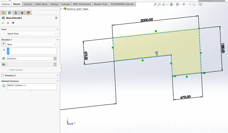
Select the surface body switch the top view of blueprint and draw a lines add the dimension then create a boss > extrude make sure the extrusion is directed upwards. As shown in figure.
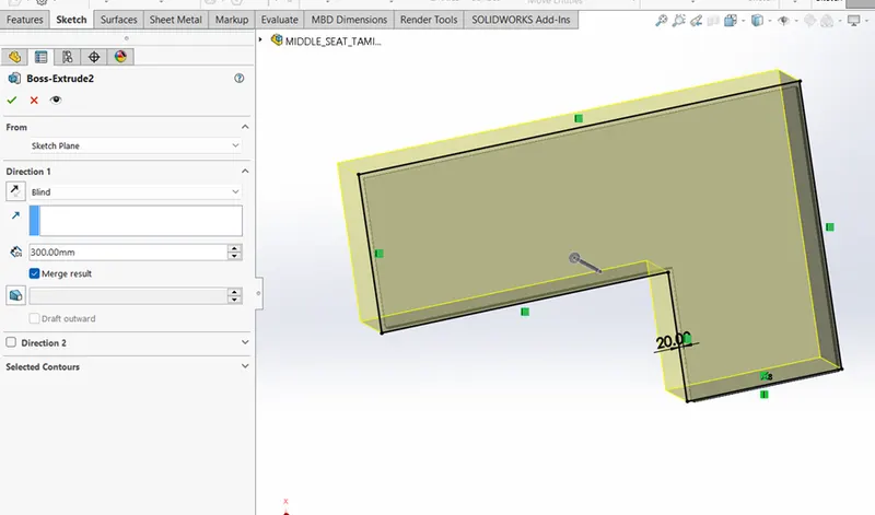
- Apply the offset entities feature on the same surface and draw horizontal line ,then trim the upper part of the offset lines and create a boss > extrude in upward direction of 300mm as shown in figure.
- Create a new plane on the selected surface by using the reference plane , draw a sketch and create an extrude on the sketch change the depth to diameter and make sure that the extrusion is directed upwards as shown in figure.
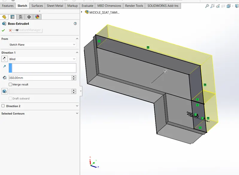
- Create a chamfer & fillet on the extrude surface by using distance option on all the edges of the middle seat.
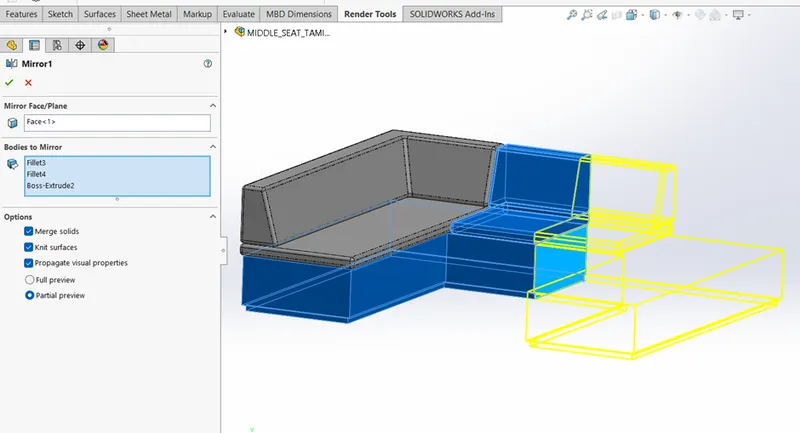
- Mirror the two main bodies of the middle seat by using pattern/mirror by select the bodies to mirror and mirror face and also select the merge solids and knit surfaces as shown in the figure.
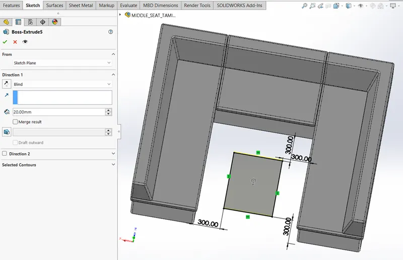
- Apply a fillet on the mirror surface bodies and create a new sketch on the hull surface , switch to the top view and draw the corner rectangle then add the dimension, and create a boss > extrude as shown in figure.
- Create anew sketch on the extrude table and create a boss > extrude make sure that the extrusion is directed upward
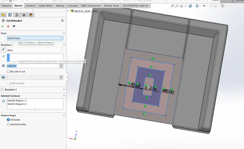
- Start anew sketch to offset the edges of the blue surface and create three offset distance od 150mm,310mm and 480 mm as shown in picture.
- Apply a appearance colour for the middle seat of the yacht.
- REAR SEAT OF YACTH MODEL:
- Seat is used for the purpose of rest; it is also an important part of the superstructure. Of the yacht.
- In rear seat of yacht accommodated with 4 persons in the modelling.
TOOLS FEATURES USED FOR MODELLING:
- Line
- Spline
- Boss > extrude
- Cut > extrude
- Surface > sweep
- Surface > loft
- Surface > trim
- Surface > knit
- Fillet
- Chamfer
- Reference geometry
- Appearances
PROCDEDURE FOR MODELLING:
- Open the blue print setup and save the file as rear seat and go to part features open the hull part uncheck all the option except the surface bodies option.
- Select the surface body switch the top view of blueprint and draw lines add the dimension then create a boss > extrude make sure the extrusion is directed upwards. As shown in above figure.
- Create a new sketch on the mid plane by using the three line and two splines add the dimensions, then create a new plane with the reference geometry and draw another sketch on the new plane.
- Create a surface sweep by select sketch as profile and sketch 2 as path.
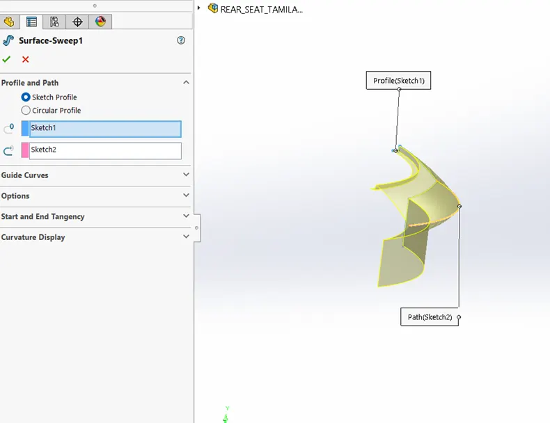
- Create a2d sketch in plane 1 by switch to the top view and draw a line add the dimensions, then trim the selected purple surface as shown in figure.
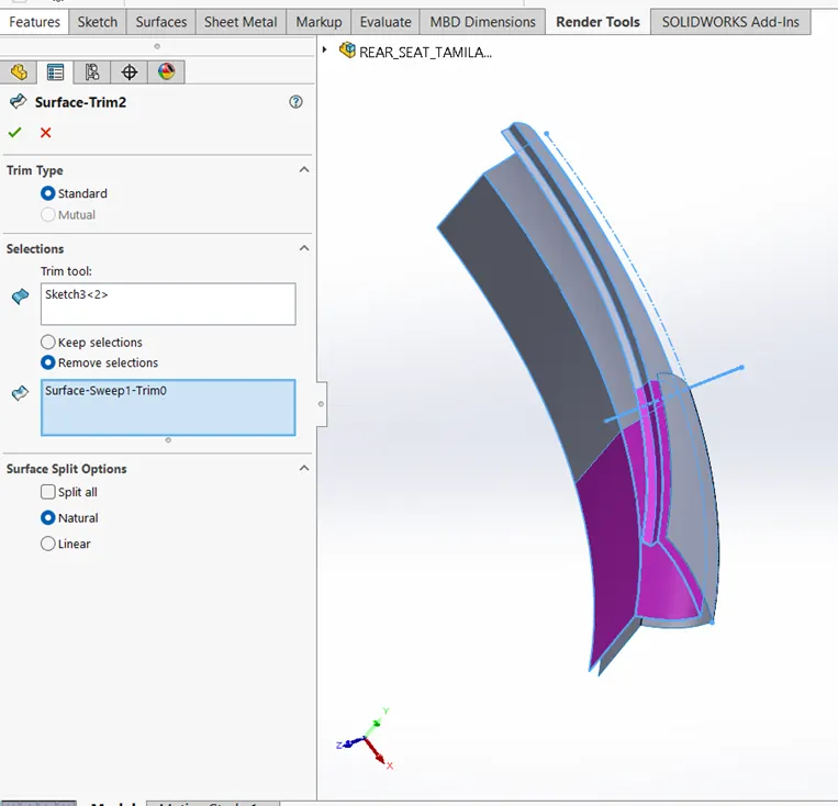
- Create a ruled surface by select the tangent to surface option and knit the two surface bodies, select the merge result and gap control option.
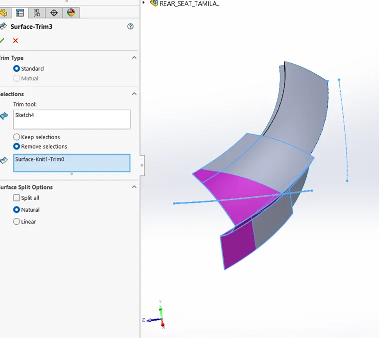
- Hide the deck surface and create a new sketch by switch the top view draw the spline and line, then create a new plane for additional sketch to make a surface sweep by selecting the profile and path as shown in the figure.
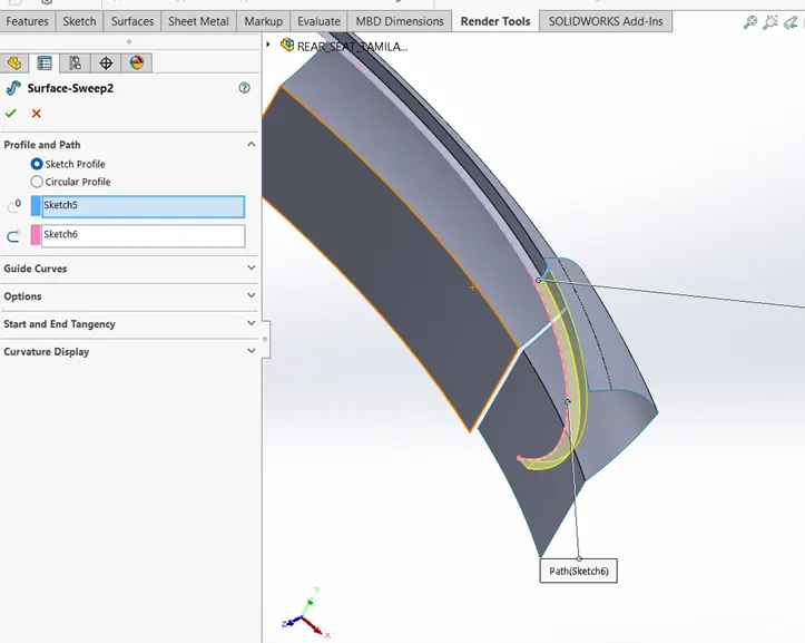
- Extend the surface of the surface sweep by selecting the edges/face to extend and trim the purple surface, then knit the two surface bodies and select the merge entities & gap control option.
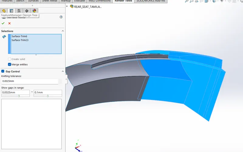
- Unhide the deck surface and create a new sketch on it by convert entities option then create surface extrude make sure the extrusion is directed upward and trim the remove selection purple surface.
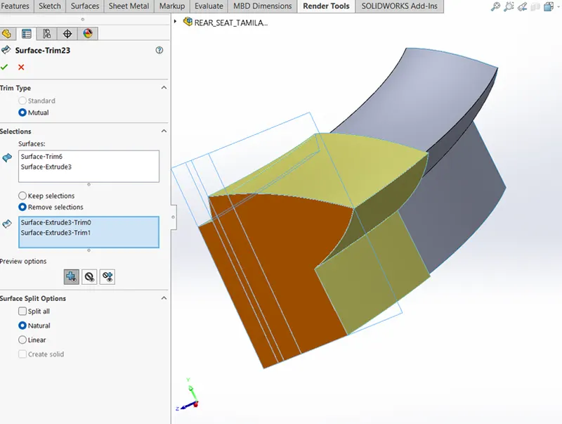
- Create a two 3D sketch and draw a convert entities then close the sketch, also create a surface loft by selecting the two 3D sketch in the feature tree and make sure that the green balls are In the same direction as shown in picture.
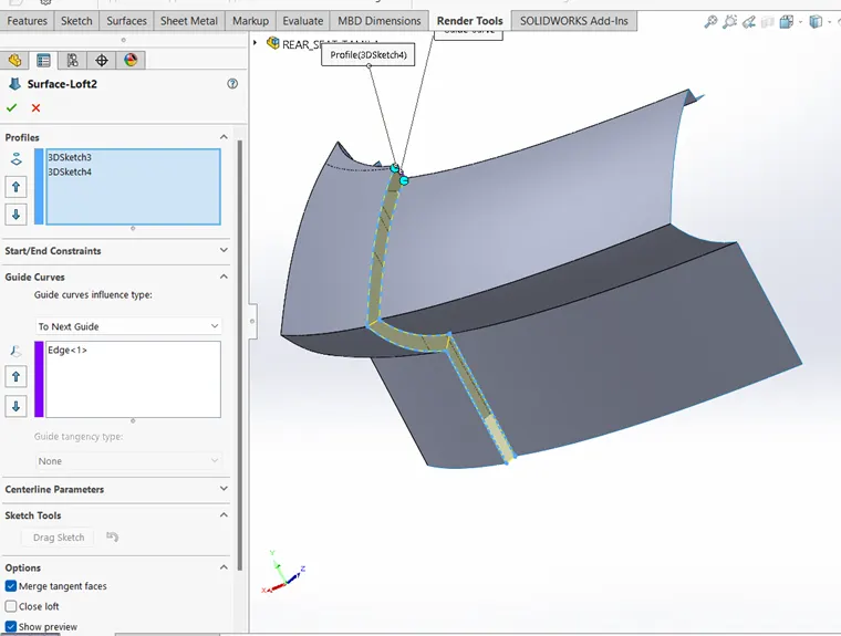
- After completing the knit surface of all three created surface then create a new 2d sketch by sketch tool > convert entities and make a surface extrude the line up to surface.
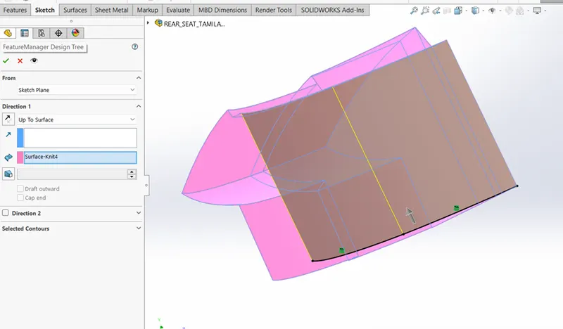
- Add another one surface loft in the model then create a knit the all-surface bodies and select the “merge result” and “gap control” option
- Hide the deck surface and create a surface loft in the bottom of the model, select the two edges and make sure that the balls are both on the same end.
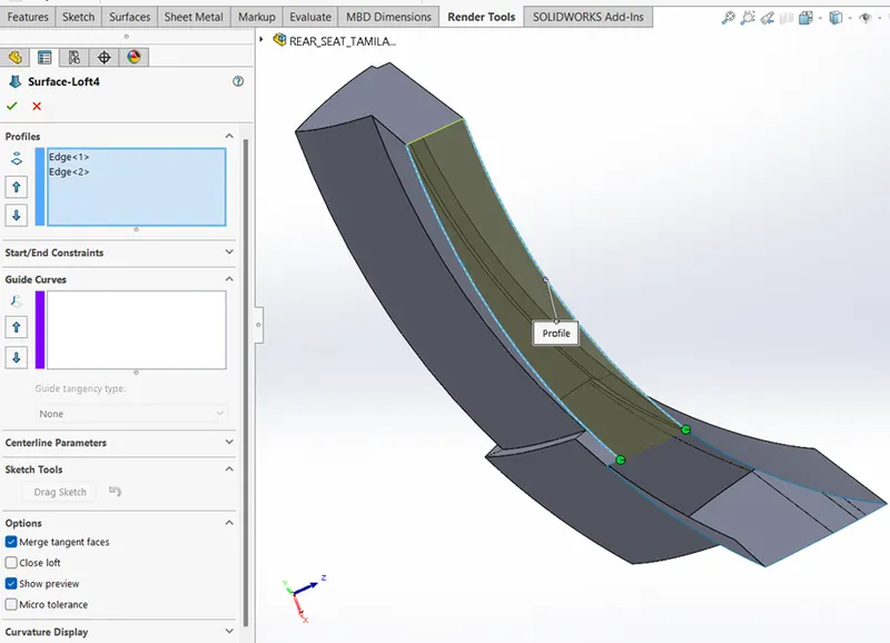
- In order to solidify this model, you must first fill the small gab in the model so extrude the surface of surface loft 4 by select the two edges and select distance as end condition then select the same surface as extension type.
- create a new sketch on the deck surface of the hull by using the convert entities select the two edges switch to top view and draw a line and spline add the dimension & relation for fully defined, then create a boss > extrude as shown in figure.
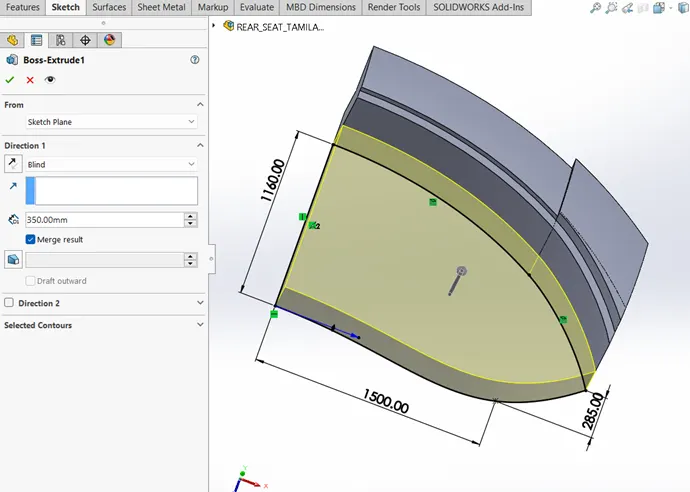
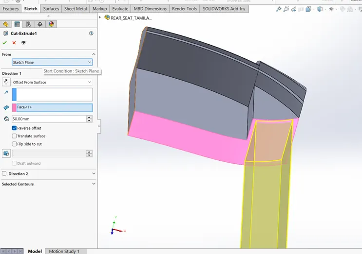
- hide the deck surface and create a new sketch select the front plane to draw a rectangle and add the dimensions, then offset the rectangle in inward direction for 5mm and apply a cut > extrude offset from the surface and select pink surface as face.
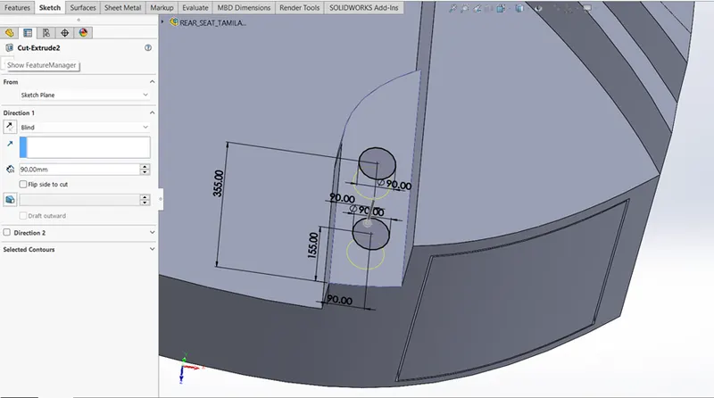
- create anew sketch on the surface of the model by drawing the two circles and add dimension as shown in the picture and create a extrude cut towards the deck surface, then create a chamfer and fillet for the surface knit bodies.
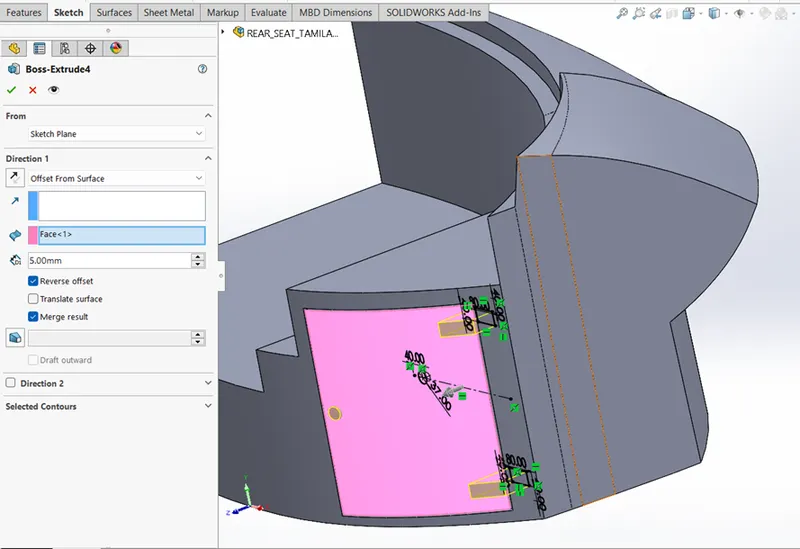
- create a new plane and click on the 2D sketch to draw circle and two corner rectangle then add the dimension & create a extrude indirection of offset from surface and make sure that the extrude direction is pointer outwards.
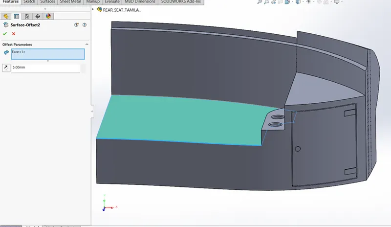
- create a new sketch on r the rear seat surface by using convert entities & create a boss > extrude 60mm make sure that the extrusion is directed upwards, then create a surface offset 5mm in directed upwards as shown in figure.
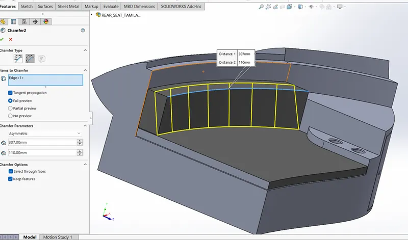
- draw a2D sketch on the offset surface by using convert entities and create a boss > extrude D1 – 300mm, make sure the extrusion ids directed upwards ,then create chamfer on the extrude surface by selecting distance * distance option D1-307mm & D2-110mm.
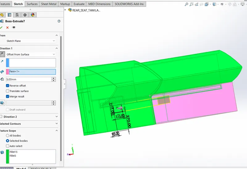
- apply a fillet for all the edges of the created surface bodies and create n new sketch on the back of the rear seat then apply a boss > extrude in offset from surface make sure that the extrude direction is pointed outside as shown in figure.
- create a new plane to draw a sketch by using line and sketch fillet add dimension ,then using this sketch create a new plane draw a sketch using circle give a dimension and apply a boss > sweep bu selecting the profile and path as shown in figure.
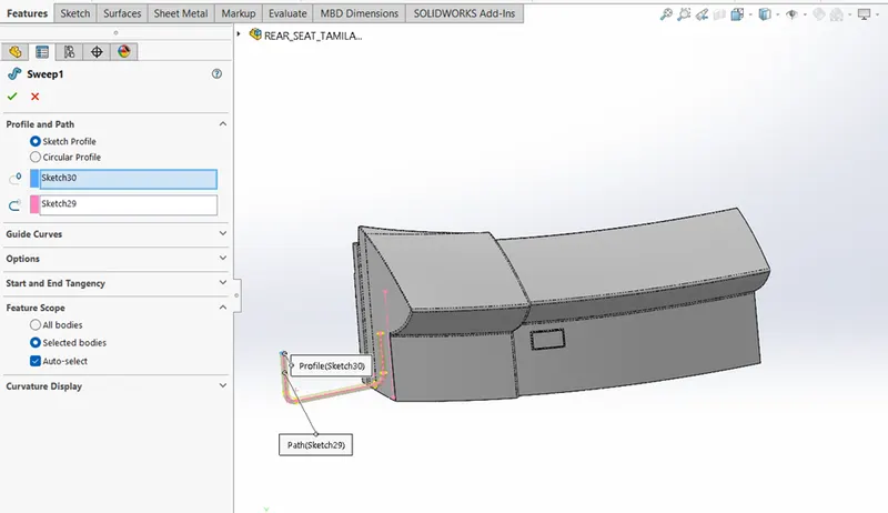
- start anew sketch on created new sweep surface draw a circle and line and create another plane to draw a circle and apply boss > sweep by selecting the profile and path
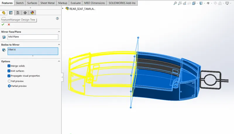
- mirror the rear seat by selecting the mid plane as mirror face and select the bodies to mirror, then select the “ merge solid” & “ knit surface “ option.
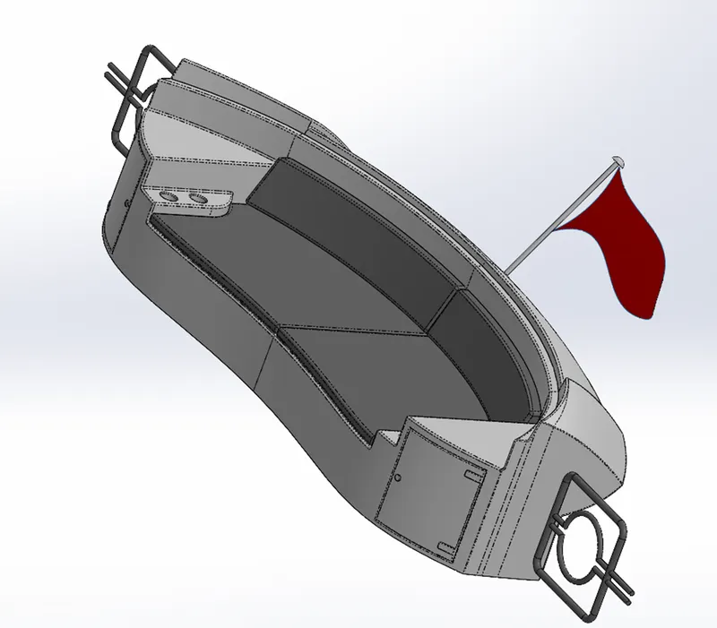
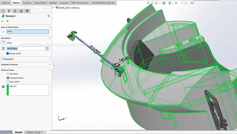
- create a new sketch in the mid plane draw the line of the flagstaff and add the dimension then apply a boss > revolve feature about an axis of revolution line as shown in figure.
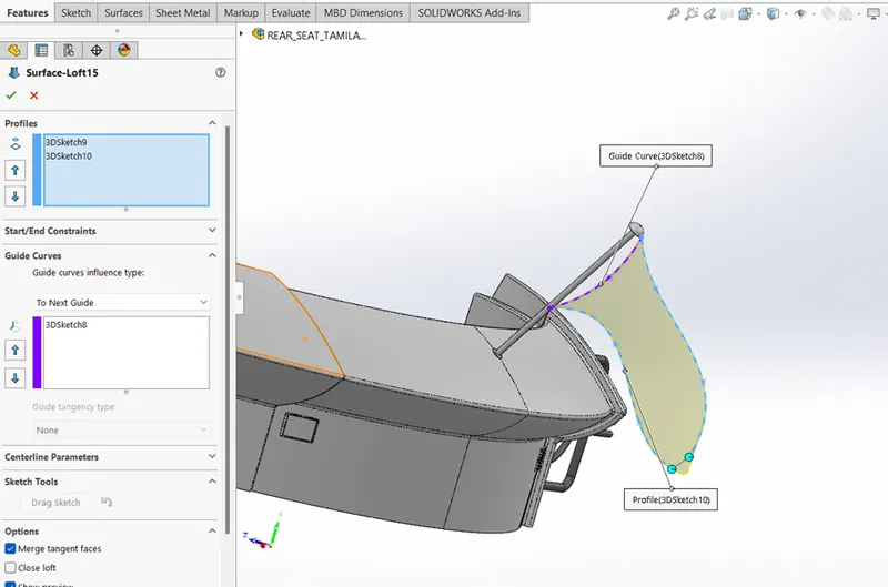
- create a 3D sketches for the flag by using the 3D spline to simulate the flag contour, then create a surface > loft by selecting the 3D sketch as profile and make sure the balls are in same direction.
- finally apply an appearance for the rear seat of the yacht model by using Appearance feature.
- SUPERSTRUCTURE:
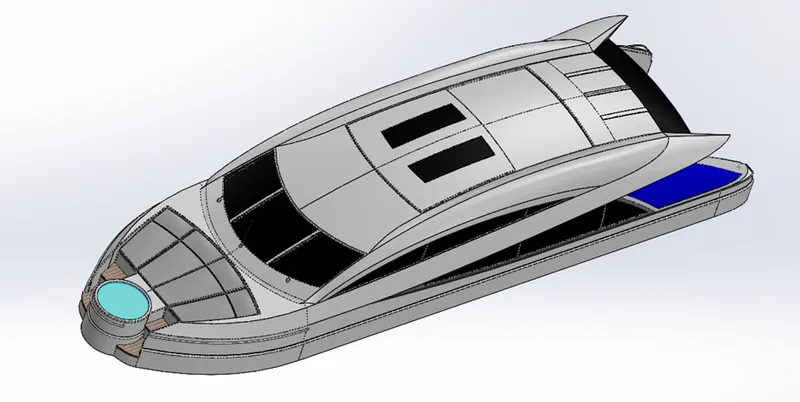
- A superstructure is an upward extension of the yacht. It is like ahead &gives a pretty good look and mounted over the hull.
- It is main control room of yacht.
- By the base isolation whole yacht can be protected from severe damage.
.
TOOLS FEATURES USED FOR MODELLING:
- Line
- Spline
- Boss > extrude
- Cut > extrude
- Surface > sweep
- Surface > loft
- Surface > trim
- Surface > knit
- Fillet
- Chamfer
- Reference geometry
- Appearances
PROCDEDURE FOR MODELLING:
- Open the blue print setup and save the file as superstructure and go to part features open the hull part uncheck all the option except the surface bodies option.
- Create new sketch on the deck surface by using a line and spline add the dimension and relation for them , then create a surface extrude and make sure that the extrusion is directed upwards as shown in figure.
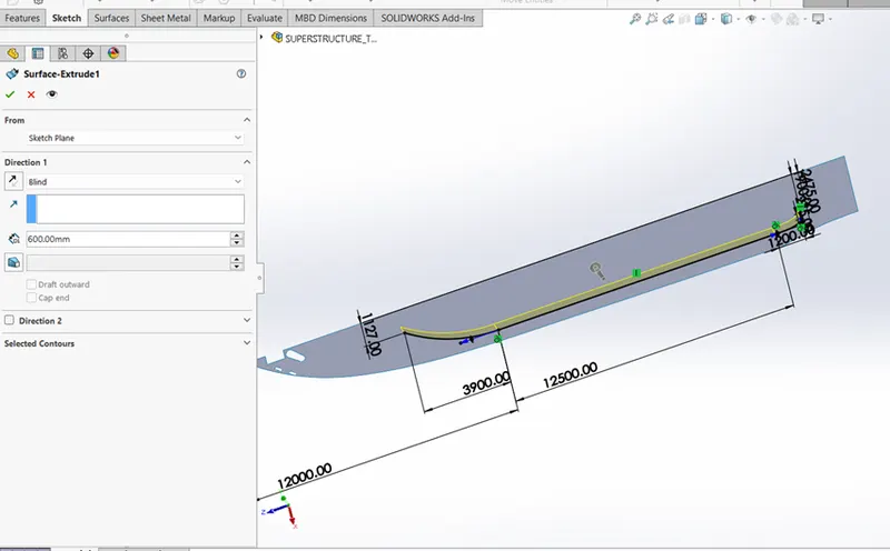
- Make a new plane on the extrude surface and create a new sketch then draw a horizontal line add the dimension and relation & create 3D sketch select the upper edges of the surface extrude to apply convert entities, then create a surface sweep by selecting the profile and path as shown in figure.
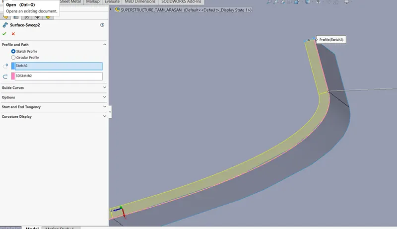
- After complete surface sweep apply a knit the surface of the superstructure and fillet the sweep edges, create a ruled surface by selecting the edge selection and draft is directed inwards.
- Create a new sketch on the mid plane draw a line and spline add the dimension and relation for them.
- Trim the upper surface select the “remove selection “option and select the purple surface above the cutline as shown in figure.
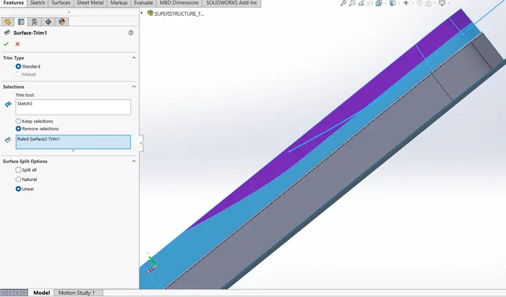
- Create a new sketch on the mid plane by using the convert entities and draw a spline pull the arrow to match the curve of the blueprint and add the dimension & create a new sketch on the top plane with convert entities and spline. then create a projected curve by selecting the two sketches to project.
- create a new sketch on the top plane and draw an offset entities in inward direction then draw spline of the superstructure and trim the end of the offset edge & create anew sketch on the mid plane draw a line and spline push the arrow to match the curve of the blueprint.
- Create a projected curve by selecting the two sketches and create a3D sketch draw the line in the picture and connect it with the endpoint of curve1 and curve 2 then create 3 more 3D sketch to apply a surface > loft & surface > fill as shown in figure.
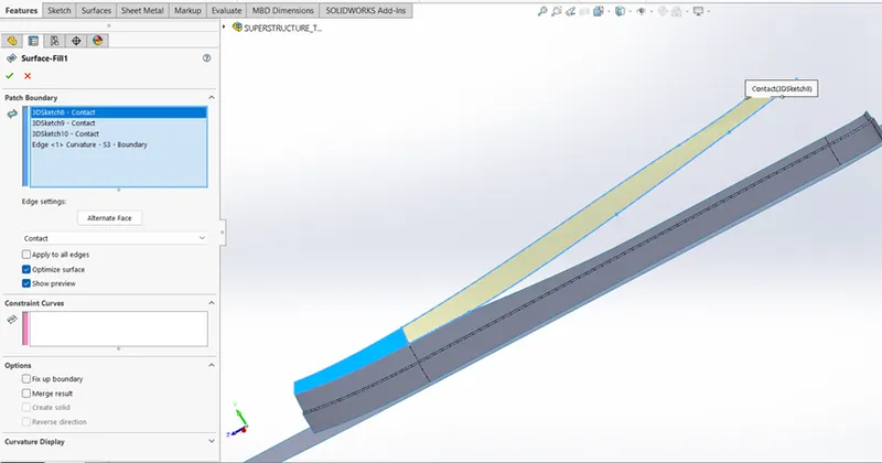
- Select the mid plane and create a new sketch by using the line and spline of the window curve as shown in the blueprint and add the dimension, then trim the unwanted surface and knit the surface of the superstructure.
- Create a 3D sketch draw straight line of the superstructure and connect the endpoint of the line with the superstructure and create a surface fill on the 3D sketch as shown in figure.
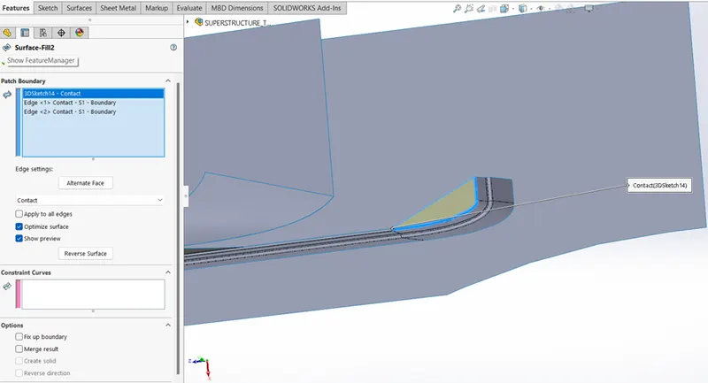
- Create a new sketch on the plane 2 draw a spline select the left side of the spline and make this tangent to surface sweep and create a surface loft by selecting the edge of the blue surface and 3D sketches.
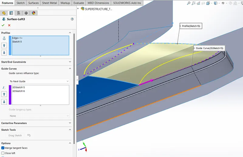
- Create a new sketch on the mid plane and top plane by using the line, spline, convert entities features. Then create a projected curve by selecting the two sketches.
- Create a two-3D sketch select the edges of the surface – fill and convert entities and draw a spline connect the endpoints of the spline with curve3 and curve 4, then create a surface loft as shown in the figure.
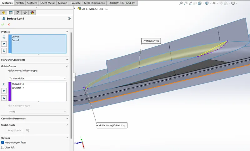
- Create a 3D sketch select the upper edges of the surface extrude and convert entities the line, then create a ruled surface as shown in the figure.
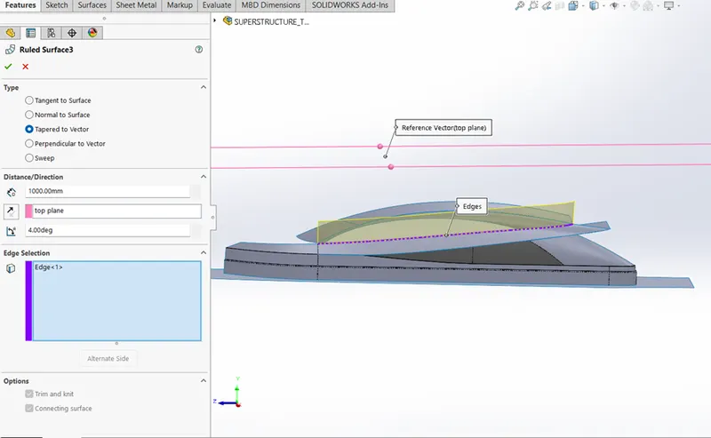
- Select the mid plane start a new sketch by using the spline of the window curve as shown in the picture, then trim the upper surface.
- Knit the surface of the blue parts of the superstructure.
- Create a new sketch on the top plane using spline feature with the endpoint of the surface loft and the mid plane and pull the arrow to match the curve of the blueprint. Trim the right surface.
- Create a3D sketch draw the straight line and connect it with the endpoint of surface loft and create a surface loft by select the new 3D sketch & edge and select the guide curves as edge of the loft guide curves.
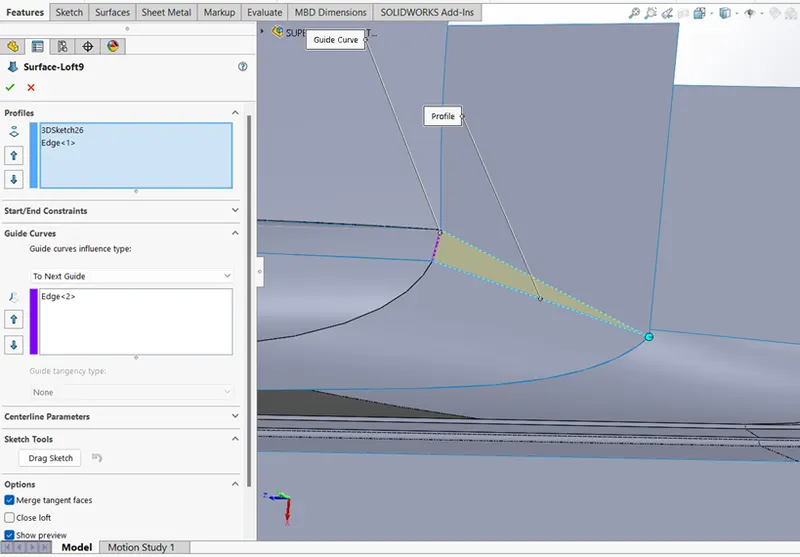
- After extend the surface of surface loft and trim the inner surface we have to knit the blue surface of the superstructure.
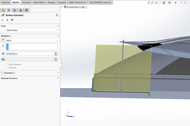
- Select the lower blue surface to create a new sketch draw a straight line and create a surface extrude as shown in the figure
- Select the deck surface of hull and create a new sketch by draw spline connect the spline with the endpoint of surface extrude and the edge of the deck surface. And create a surface extrude by change the direction to up to surface, then knit the surface.
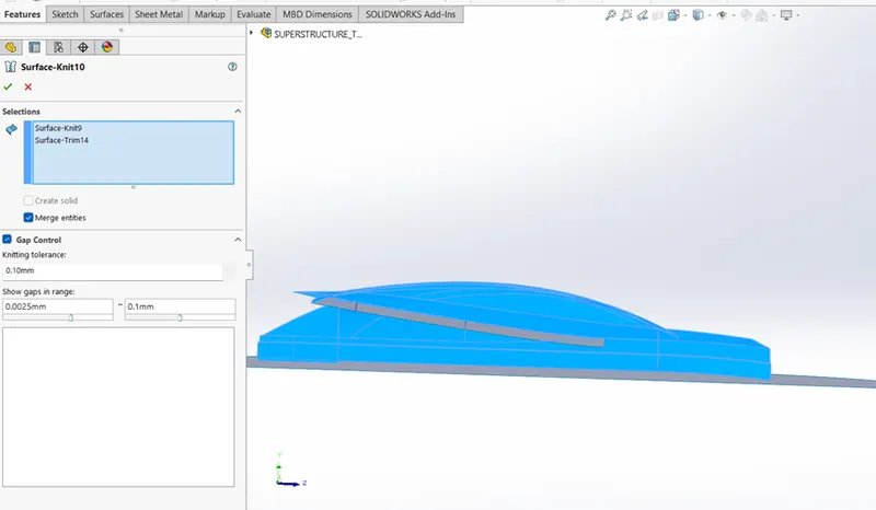
- Create a new sketch on the top plane draw the two splines as shown in the blueprint add the dimensions. Select the upper endpoint of the spline and add a horizontal relation then select the power endpoint of the spline and drag at the arrow to match the curve of the blueprint and trim the inner surface & knit the surface of the superstructure.
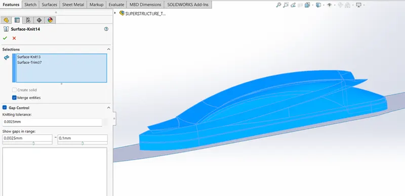
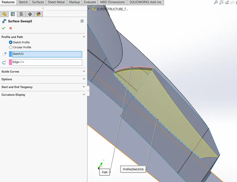
- Create a surface extrude in upwards direction and trim the upper surface then create a new sketch on the mid plane draw a spline add the dimension. & Create a surface sweep by selecting the profile and path.
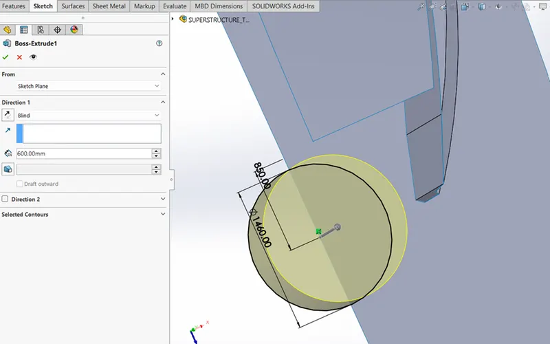
- Draw a circle at the deck surface of hull and add the dimension then create an extruded boss, make sure that the extrusion is directed upwards as shown in the picture.
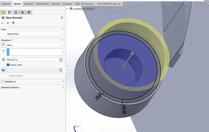
- Draw a two circle at the blue surface add the dimensions and create an extrude boss make sure that the extrusion is directed upwards. And fillet the edges of the circle
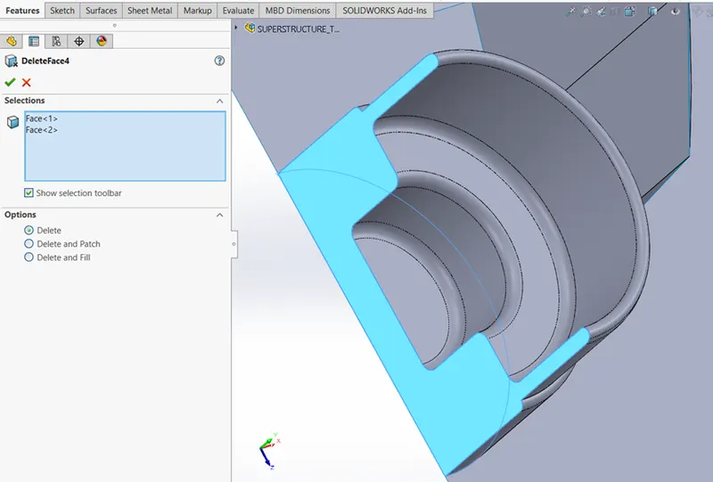
- Draw a rectangle at the blue deck surface add the dimension & create an extrude cut through all make sure that the extrusion is pointed upwards and delete the blue surface as shown in figure.
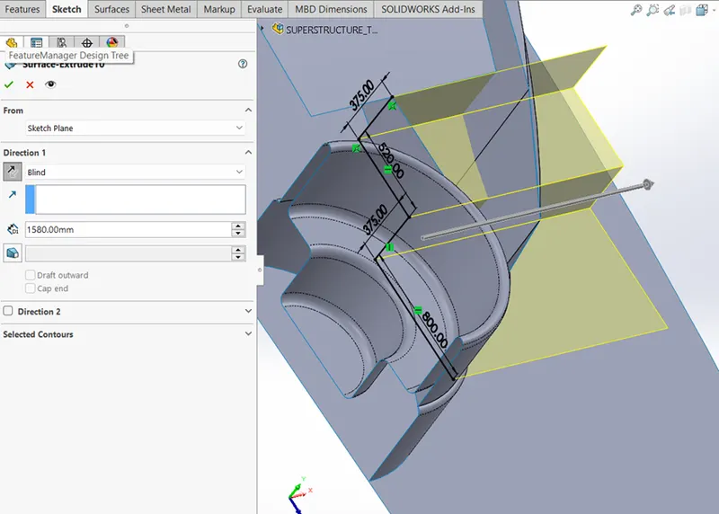
- Create a new plane draw a line and create a surface extrude up to surface then create a new sketch the new surface draws lines add the dimension, create a surface extrude as shown in figure.
- Create a new sketch on the blue surface draw a spline add the dimension drag at the right arrow of the spline to make a smooth transition, then trim the surface.
- Draw a 3D sketch to draw an extra line under the vertical edge, then create a surface sweep by selecting the profile and path & trim the purple surface and trim the purple surface below the deck surface.
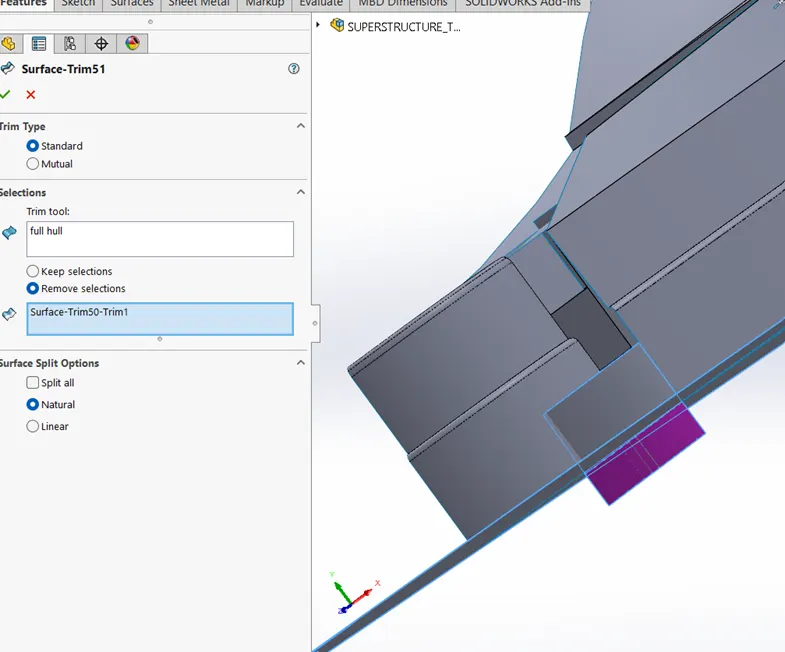
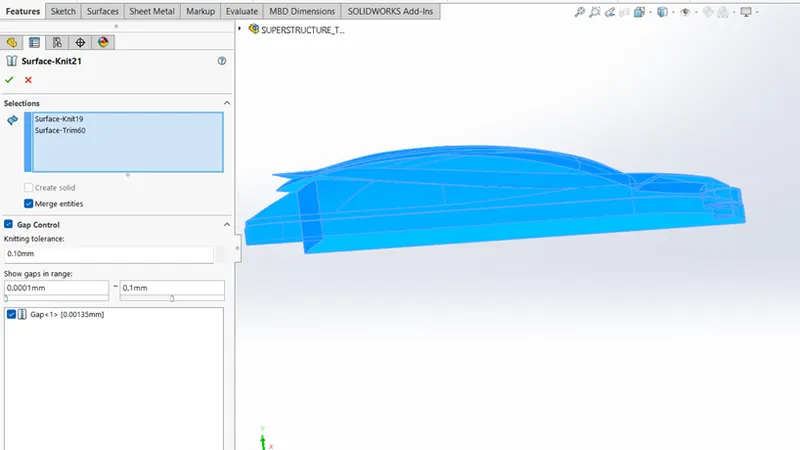
- Knit the two surface bodies and trim the deck surface then again create a knit the two all blue surface bodies and also select the merge entities & gap control option.
- create a new sketch on the bottom plane draw the horizontal line and add the dimension. And create a surface extrude make sure the extrusion is directed upwards.
- Trim the purple surface, select the outer purple surface to remove & knit all the surface of the superstructure and convert it to a solid body. Also select the “try to from solid”, “merge entities” option.
- Create a front window screen for yacht by create a2D sketch on the top plane by using offset entities and trim tools then create a extrude cut offset from surface.
- Apply a fillet on the screen and select the bottom surface of superstructure to create a sketch draw a vertical line give the dimension then create a extrude offset from surface.
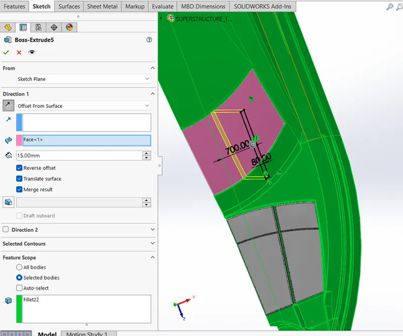
- After completing the top roof opening window then create a 2D sketch on the mid plane apply convert entities on the edges of the side window the draw four lines as shown in the blueprint.
- Create extrude on the window offset from surface and apply a fillet on the side window edges.
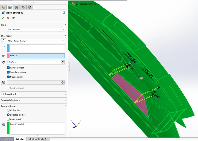
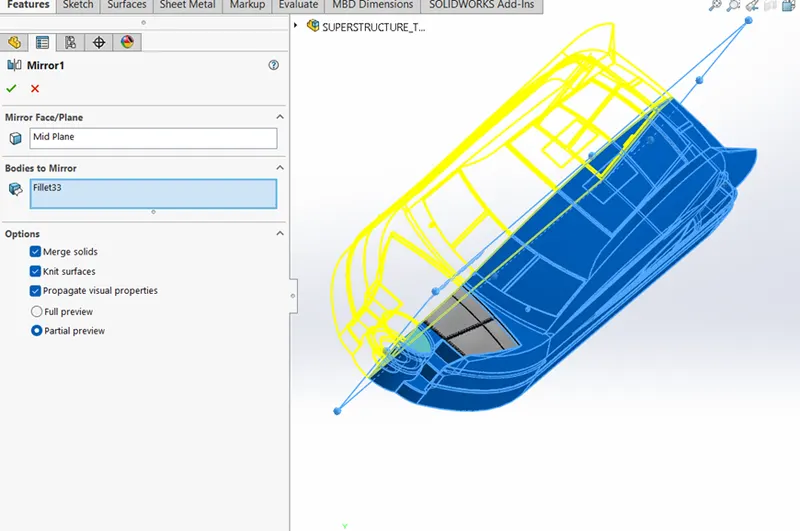
- Mirror the main body of the superstructure by selecting the mid plane as mirror face and all blue surface as bodies to mirror by using the pattern/mirror.
- Create three 2D sketch on the plane 5 by drawing a rectangle on the front window screen and apply a extrude offset from surface outwards then create a chamfer and extrude cut on the viper.
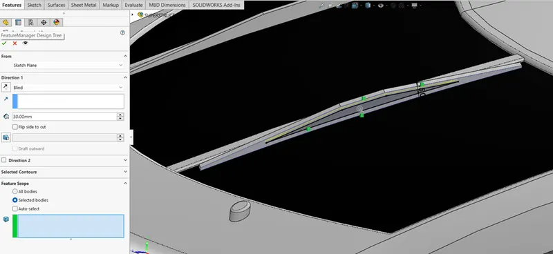
- Create a new 3D sketch draw a line and connect the endpoints of the line with viper then create a new plane with the reference of 3D sketch and draw a circle on that plane and extrude the circle alone the 3D sketch.
- Repeat it for other two viper connecting rode of the superstructure.
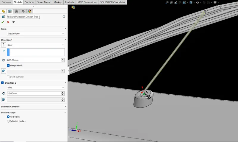
- Change the main body colour and other components by using the appearance features.
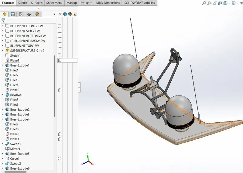
10.RADAR MAST:
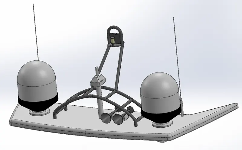
- Radar mast is device acts as a major navigation aid for yacht.
- They are made of high tensile steel with added rigidity based on the size of the derricks it holds.
TOOLS FEATURES USED FOR MODELLING:
- Line
- Spline
- Boss > extrude
- Cut > extrude
- Surface > sweep
- Surface > loft
- Surface > trim
- Surface > knit
- Fillet
- Chamfer
- Reference geometry
- Appearances
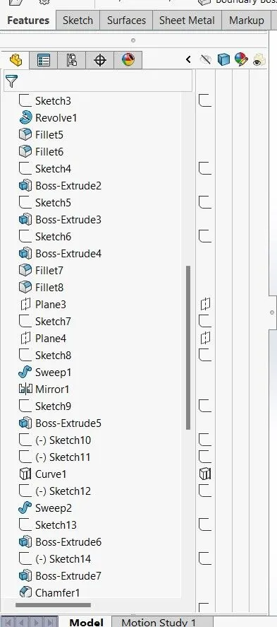
PROCDEDURE FOR MODELLING:
- Open the blue print setup and save the file as rear seat and go to part features open the hull part uncheck all the option except the surface bodies option.
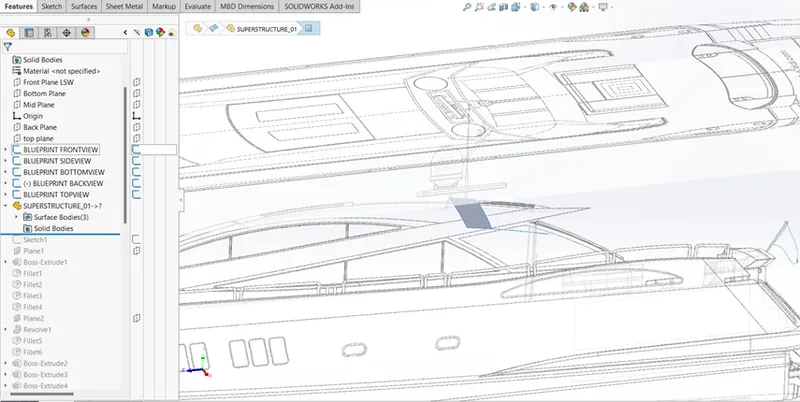
- Select the mid plane and click on the 2D sketch draw a line and add the dimensions.
- Create a new plane by using the 2D sketch as reference then sketch on the plane by draw a four spline without midpoints as shown in the picture and blueprint.
- Create an extrude and make sure that the extrusion is directed upwards.
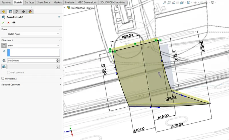
- Apply a fillet on the extrude surface.
- Create a new plane as a first reference – front plane and offset distance is 20950mm
- Start sketch on that plane by draw the line add the dimension then use the 3-point arc after completing it create a revolve by using the axis of revolution line 1.
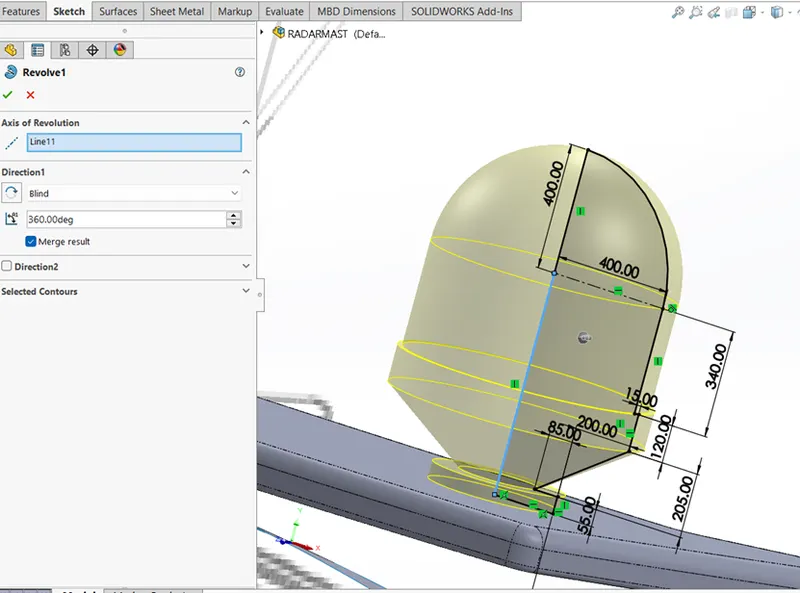
- Apply a fillet on the revolved component.
- Create a new sketch on the blue surface draw the circle and extrude the circle, make sure that the extrusion is directed upwards.
- Again, draw a circle and extrude it om directed upwards as shown in figure.
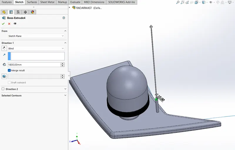
- Apply a fillet on the edges of extrude cable rode.
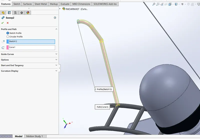
- Create a new plane to start sketch using vertical line and the diagonal spline without midpoint.
- Create another new plane and draw a circle to create a solid sweep as shown in figure.
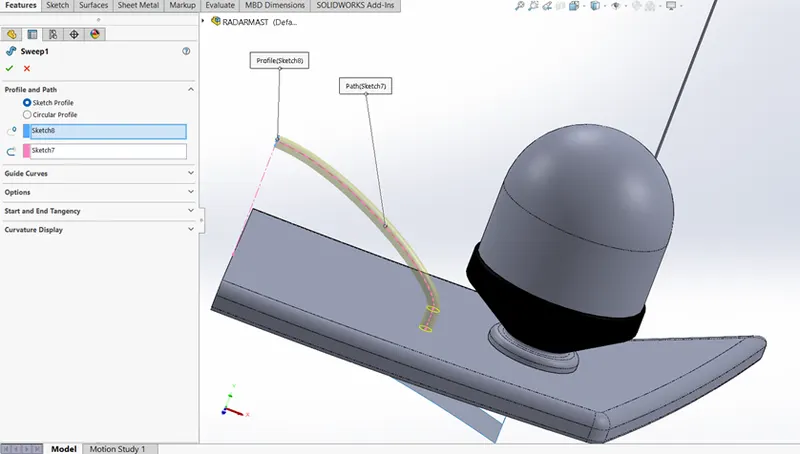
- Mirror the solid sweep by using mirror feature and create a new sketch on the plane 2 draw a circle.
- Create an extrude change the direction 1 to midplane and change the offset distance to 500mm.
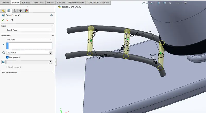
- Create a new sketch on the mid plane draw a two line add the dimensions
- Create anew plane start sketch a two lines and center point arc then create projection curve.
- Draw a circle in the created new sketch on the midplane then create a solid sweep as shown in figure.
- Create anew sketch on the blue surface draw a circle and create a extrude and again draw anew sketch by using rectangle feature add the dimension then create a extrude as shown below.
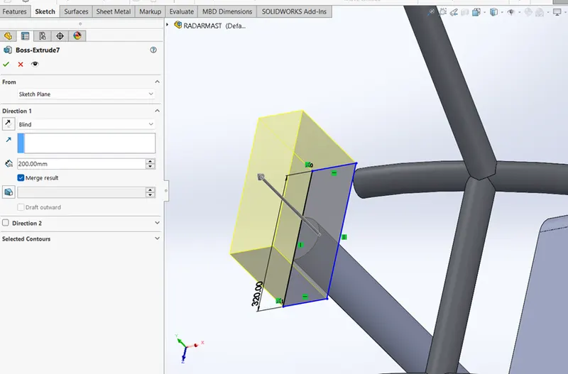
- Apply a fillet on the created rectangle extrude bodies edges.
- Create anew sketch on the midplane and draw aline as shown in figure add the dimension and create a revolve feature
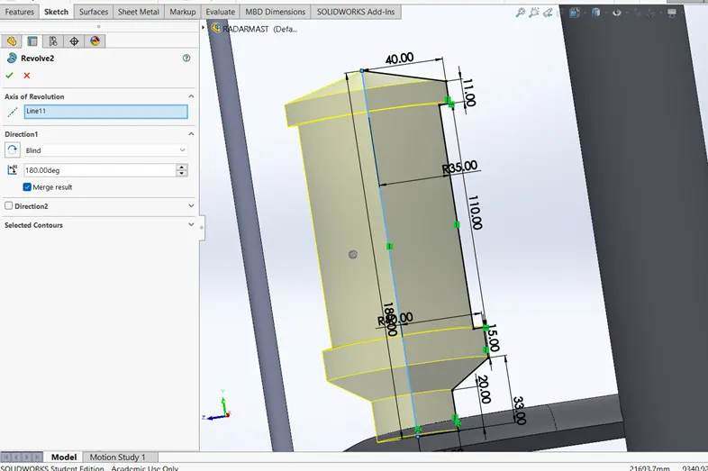
- Apply a fillet feature on the revolve solid bodies edges.
- Mirror the mast light and create a new sketch on the blue surface and draw a rectangle add the dimensions
- Create a boss > extrude change the direction to up to surface & disable the merge result option.
- Apply a fillet on the create extrude bodies edges.
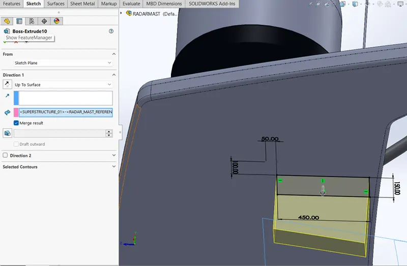
- Mirror the radar mast of the yacht by select the mid plane as mirror face and select the mirror bodies.
- Don’t select the body of horn.
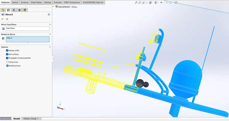
- Change the colour of the bodies of the radar mast, radar, two antennas, mast an the light of the radar mast of yacht.
ASSEMBLY OF YACHT
- In Solidworks software the assembly is one of the major steps to complete the modelling. To make the assembly we have to mate then in basic relation between the two components.
- Assembly is useful to give the more realistic outlook of the YACHT.
- The Solidworks assembly mates consists of 3 main mates they are;
- Mechanical mates
- Standard mates
- Advanced mates
- MECHANICAL MATES:
- Universal joint
- Gear
- Rack & pinion
- Cam
- STANDARD MATES
- Width mates
- distance mates
- angle mates
- coincident
- concentric
- parallel
- perpendicular
- tangent
ADVANCED MATES:
- Profile centre
- Symmetric
- Path mates
- Linear coupler
PROCEDURE FOR ASSEMBLY:
- Import all the parts manually by insert components option in assembly manger
- Then fix the hull part by applying the coincident mate to the top, right, and front plane of the assembly.
- Then for each part apply necessary mates required by the blueprint using different suitable mates.
- Advanced mate was also used wherever required.
- Finally fix the assembly origin and hull origin in coincident mate features
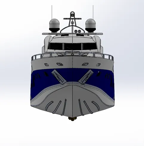
FRONT VIEW OF YACHT:
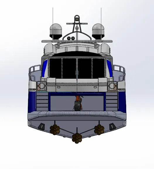
REAR VIEW OF YACHT:
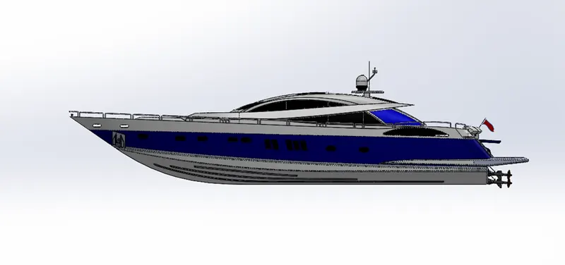
SIDE VIEW OF YACHT:
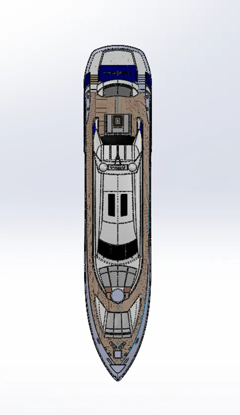
TOP VIEW OF YACHT:
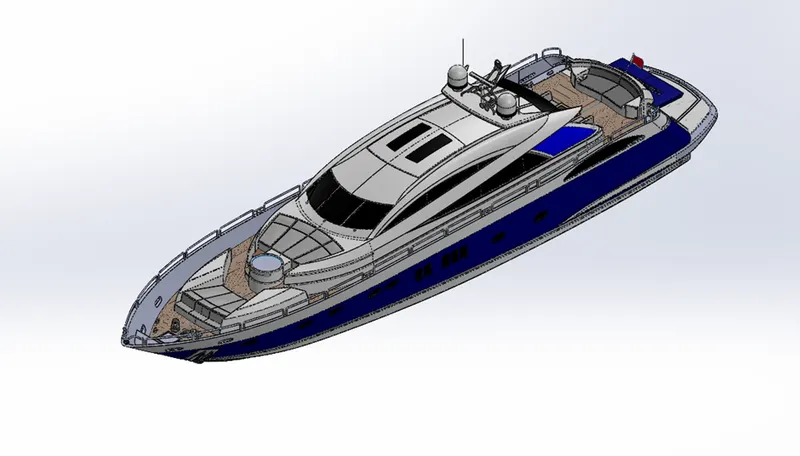
ISOMETRIC VIEW OF YACHT:
- RENDERING:
- To make the YACHT realistic we have to create high quality images and graphical appearance in the various environments and lighting back grounds.
- In Solidworks software for rendering we use photo view 360 features which is in built add in Solidworks.
- RENDERING PHOTO VIEW 360:
- First select the tool tab and search (Add in) commend to active the photo view 360 rendering.
- in photo view 360 it has various features like:
- Edit Appearance
- Edit scenes
- Edit decal
- Preview window
- Render region
- Final render
- Option
- Network rendering
- Final image type
- In Edit Decal we can add image on the component selected surface by mapping value in coordinate direction and select the axis XYZ origin.in illumination select the underlaying appearance for better decal.
ISOMETRIC VIEW:
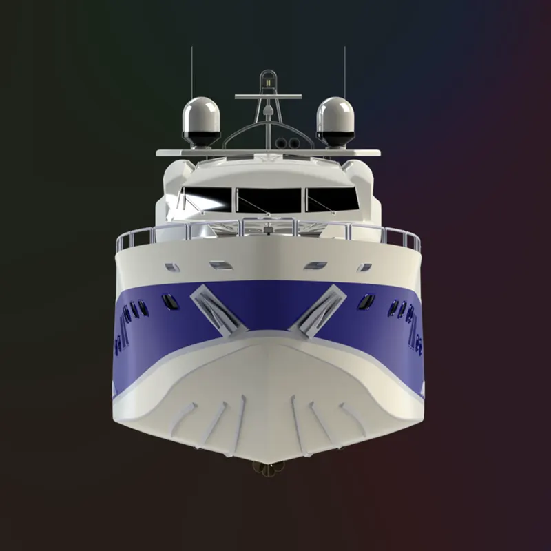
FRONT VIEW:
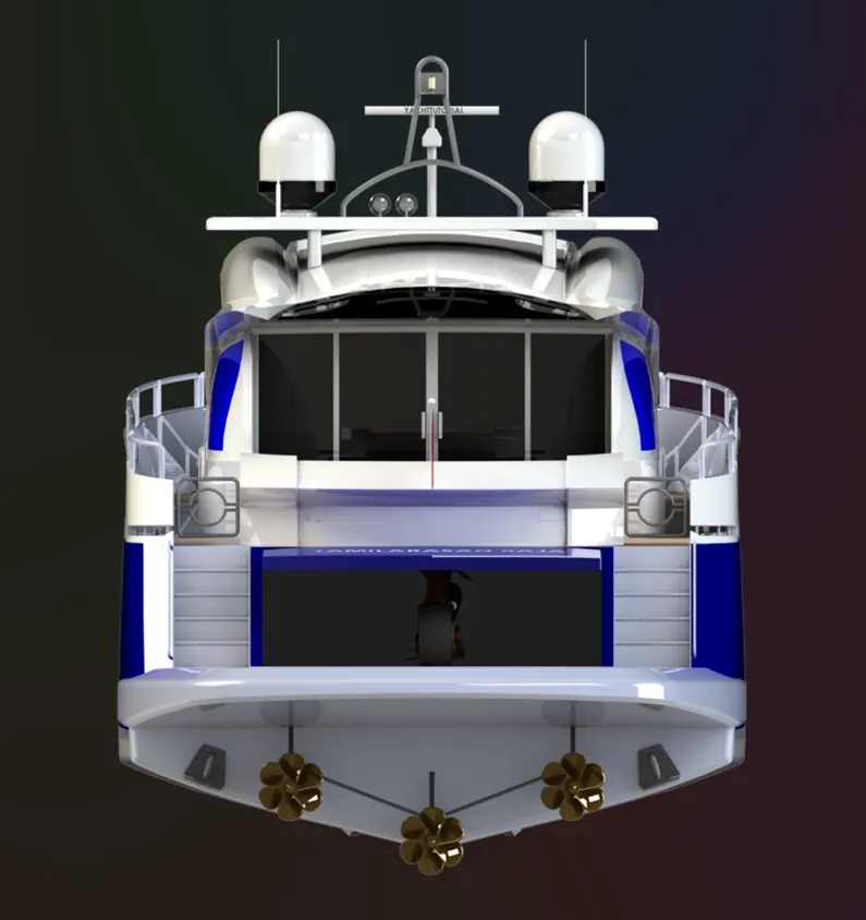
BACK VIEW:
- in photo view 360 we can adjust the lighting of the scene’s setup in camera views by view dropdown.
CONCLUSION:
- In Solidworks the Parts, Assembly and rendering of photo view 360 of the YACHT modelling is successfully completed.