Photo Realistic Rendering
AMERICAN CHOPPER MOTORCYCLE DESIGN REPORT USING SOLIDWORKS_ TAMILARASAN
Objective:
- To design, assembly and render all the individual parts of the American chopper motorcycle model by using the design tool - Ultimate Solidworks.
- By the usage of sketch tools with fully defined importance of mates in assembly.
- To render the chopper model by usage of rendering tool in Photo view 360 method.
Software Used:
- Solidworks – 2020
Introduction;
- Solidworks: is a solid modelling computer-aided design (CAD) and computer-aided engineering (CAE) program published by Dassault Systems
- Solidworks has three major environments namely:
- Part
- Assembly
- Drawing
- Part – modelling is a 3D solid modelling in Solidworks with Parametric modelling and feature based approach simultaneously wherein parameters determine the shape and geometry of the solid model, converting 2D sketches into 3D models requires the feature-based approaches
- Assembly-In this environment the various parts can be Mates to each other. Mates are categorized into general, Advanced and mechanical mates. The constraints between two parts such as Concentric, Parallel, Coincidence and Tangency
- Drawing-It is mainly used to create 2D sheets with all main views of the solid parts and assembly. This sheet details and information is used for manufacturing of the component such as geometric dimensions, tolerance and section views for required part and assembly.
- In the Solidworks software the file formats for modeling
- Parts- (. SLDPRT)
- Assembly- (. SLDASM)
- Drawing- (. SLDDRW)
MODELLING OF AMERICAN CHOPPER:
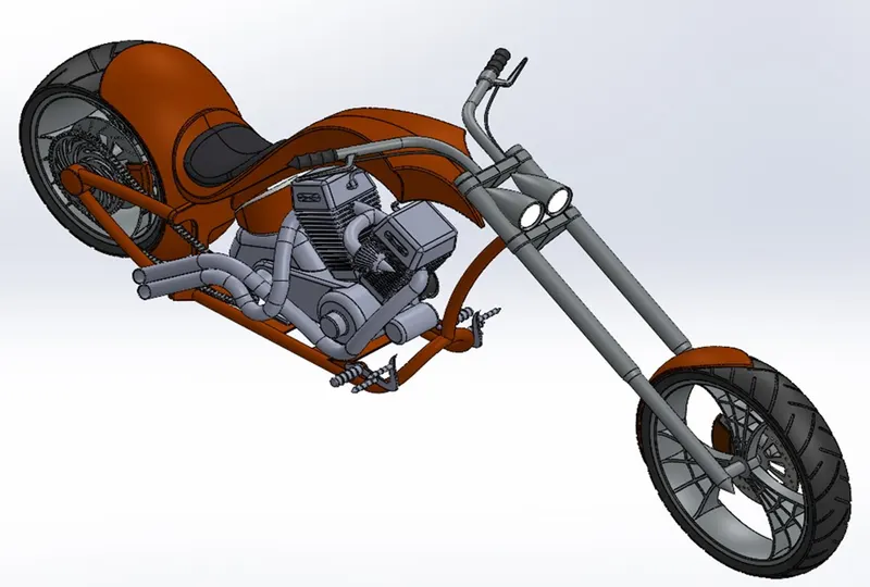
- The American chopper modelling is consisted of the following parts
- Transmission Belt
- Kickstand
- Front Fender
- Rear Fender
- Chain
- Oil Tank
- Pedal
- Front Wheel
- Rear Wheel
- Front Forks
- Chassis
- Engine
- Gas tank
With the help of Solidworks software all the parts are designed and assembled together for getting perfect modelling of The American Chopper Motorcycle with high rake angles and trail, low seat heights low ground clearance, long wheelbase and long front suspension travel
DESIGN METHODOLOGY:
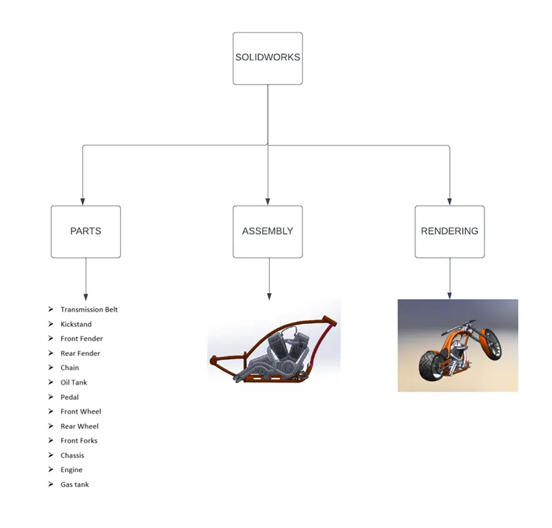
DECRIPTION:
- The American chopper solid modelling of all the parts is Sketch and Features is explained in this parts section briefly
- PARTS
1.TRANSMISSSION BELT:
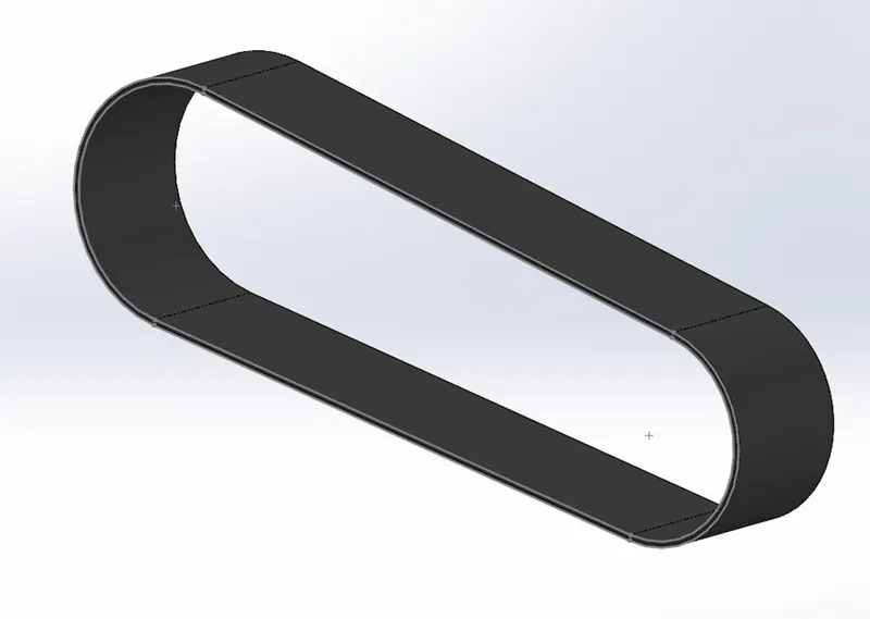
- Transmission belt play important role in Chopper it is used to drive the chain shaft driven by the engine flywheel.
- It transmits power from one shaft rotating pulley to another component. The transmission belt is made of Rubber canvas material.
TOOLS FEATURES USED WHILE DESIGNING
SKETCH TOOLS:
- Line
- Circle
- 3-point arc
FEATURES TOOLS:
- Boss Extrude
- Fillet
PROCEDURE FOR MODELLING:
- In sketch tool – Select the front plane.
- Draw the 350 mm line above and below to connect both by using 61mm and 70mm arcs, all the lines and arcs in tangent relation.
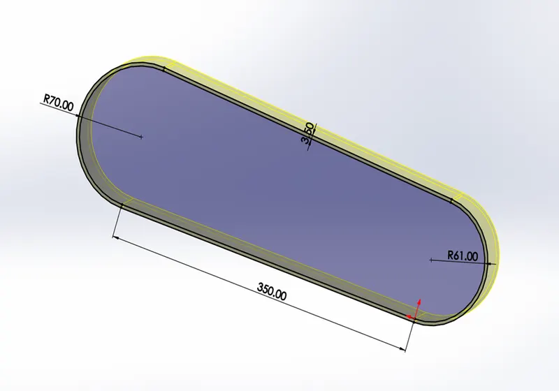
- Then the whole sketch is used to offset sketch in 3.5mm outer side direction
- In features tool – Extrude the sketch blind 88mm
- Then fillet the edges of the belt 88mm
- KICKSTAND:
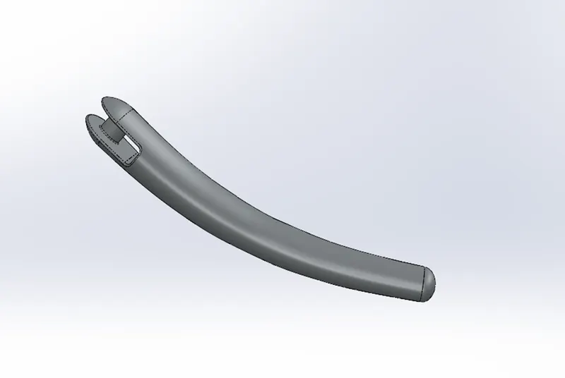
- In chopper motorcycle the kickstand is used to support the motorcycle in rest position
- The kickstand is fixed in chassis of motorcycle to withstand the load
- It has a free movement of 90 degree for swayed up when not required
TOOL FEATURES USED WHILE DESIGNING
SKETCH TOOLS:
- Line
- Spline
- Ellipse
- trim
- Pierce
FEATURES TOOLS:
- Boss Extrude
- Extrude cut
- Dome
- Fillet
- Split
- Loft
- Appearance
PROCEDURE FOR MODELLING
- In sketch tool –select a front plane, sketch a ellipse width-40mm and height 18mm
- Create a spline sketch perpendicular to the front plane to the other end of spline and sketch an ellipse of width 30mm and height 12mm
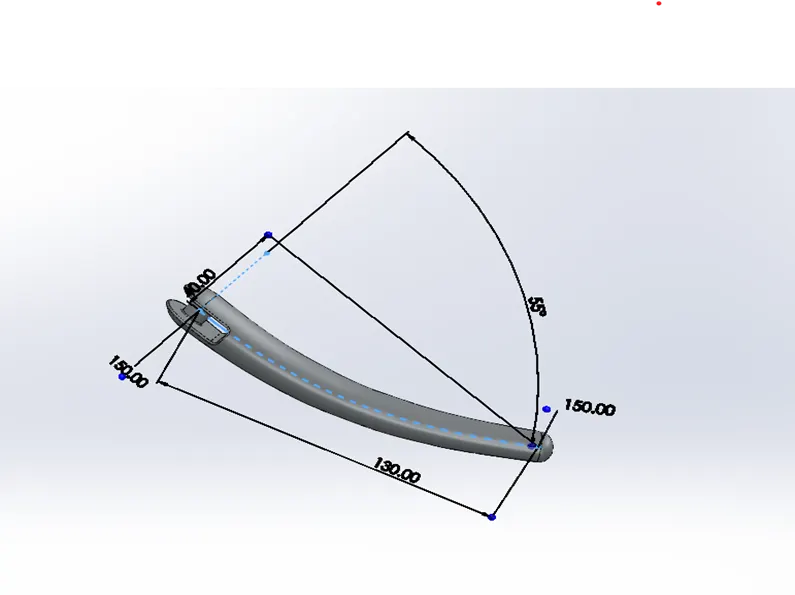
- Make a pierce relation between the ellipse and the spline
- Then loft feature the centre line by selecting the spline as the centre line and the 2 ellipses as references
- Use split feature to create a flat bottom cut for the kickstand
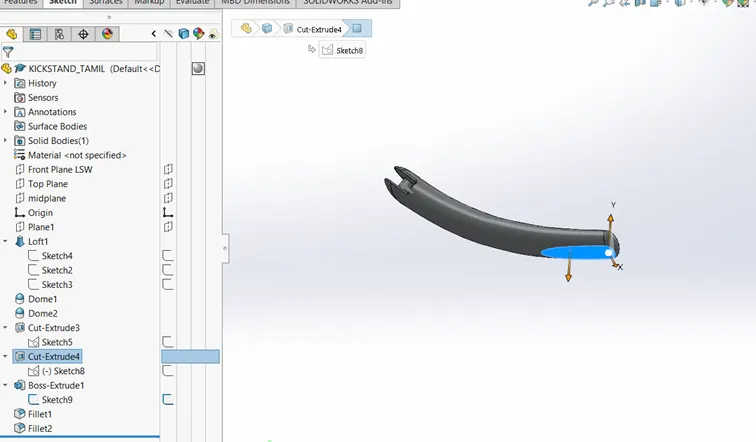
- Sketch a rectangle on the right plane origin width 28mm and height 8mm for the extrude cut feature
- In features tool – Use Extrude cut of the rectangle through all both to create cut for stand mount
- Then use sketch circle 9mm diameter on the cut surface to make another Extrude cut
- Create fillets of 2mm and 0.5 mm for the extrude cut edges.
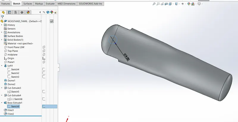
- Use Dome feature on the both side of kickstand.
- Apply the appearance-chromium plate.
- Save the part as kickstand.
3.FRONT FENDER:
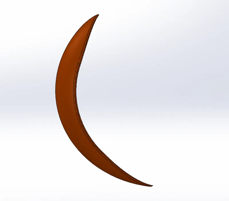
- In the vehicle the fender is use as guard to prevent sand, mud, liquids and stones
- It is also called as mud guard
TOOL FEATURES USED WHILE DESIGNING
SKETCH TOOLS:
- Line
- 3-point arc
- Spline
- Offset entities
FEATURES TOOL:
- Revolve
- Split
- Fillet
- Dynamic mirror entity
- Appearance
PROCEDURE FOR MODELLING:
- In sketch tool-Create a new document and rename the Front, Top and right as Vertical plane front fender, Centre plane front fender and mid plane front fender.
- Select a vertical plane front fender and create a construction line for 200mm and sketch another line 280 mm above the construction line.
- Sketch a 3-point arc of radius 125mm and end point distance 160mm.
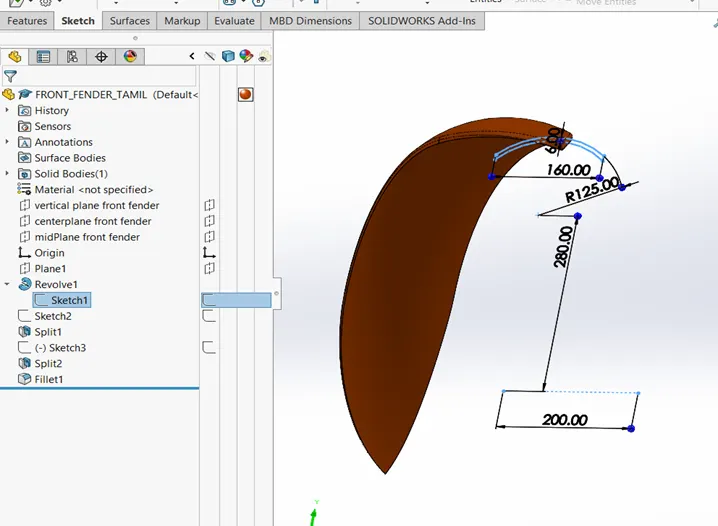
- Give the horizontal relation for end point of the 3-point arc and apply sketch offset with bound of 6mm inwards.
- In feature tool-Revolve the closed sketch about the origin line with direction1-5 degree and direction2 – 130 degrees.
- Create a centre construction line and apply dynamic mirror entity for the line and use split feature to cut parts to create an aesthetic cut on the both end of fender.
- Apply Fillet 6mm on the edges of fender.
- Apply an appearance> painted >car> Siena.
4.REAR FENDER:
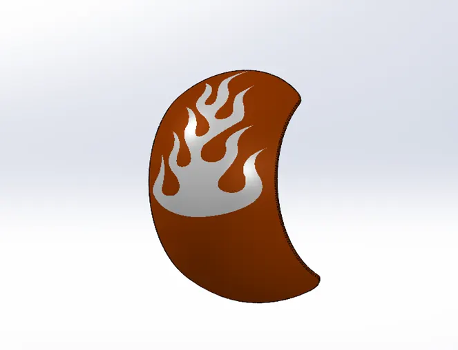
- The rear fender fixed above the rear wheel to prevent from sand, mud, rock and liquids while the vehicle in motion.
- It is also called as mud guard.
TOOL FEATURES USED WHILE DESIGNING
SKETCH TOOLS:
- Line
- 3- point arc
- Spline
- Offset entities
FEATURES TOOLS:
- Revolve
- Fillet
- Split
- Shell
- Dynamic mirror entity
- Appearance
PROCEDURE FOR MODELLIND:
- In sketch tool-create a new document and rename the front, Top and Right plane as Vertical, Centre and Mid plane rear fender,
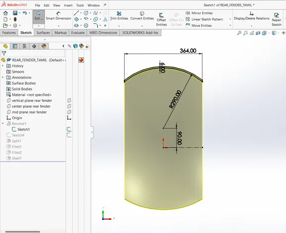
- Create a construction line horizontally and create another line above 90 mm from it.
- Sketch a 3- point arc of radius 290mm and vertical distance of 280mm from the organ to centre point of arc, end points distance 364mm and apply vertical relation of origin to the centre point of the arc
- Apply an offset entities 6mm on the inwards of the sketch
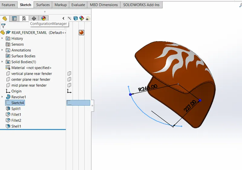
- In features tool- Revolve the closed sketch about the origin line on the axis of revaluation direction 1=10deg and direction 2= 140 deg.
- Sketch a 3-point arc of radius 265mm on another side of outer face of the fender make the distance between origin and the arc centre point 227mm
- Create a split feature to cut parts on the top face of the fender and apply fillet for 45mm on all the edges
- Apply shell feature with the value of 4mm on the inner side of the fender.
- Apply an Appearance>painted>car>Siena
5.OIL TANK:
- In motorcycle the oil tank is used to store the oil for lubrication and cooling purpose of engine
- 0il tank placed above the engine and right below the rider seat on top of the gearbox on the American chopper
TOOL FEATURES USED WHILE DESIGNING
SKETCH TOOLS:
- Line
- 3-point arc
FEATURES TOOLS:
- Boss Extruded
- Fillet
- Combine
- Shell
- Appearance
PROCEDURE FOR MODELLING:
- Create a new document and rename the Front plane to Mid plane oil tank.
- Sketch a horizontal construction line on the top plane length of 230mm through the origin and sketch a line 50mm on the below end of the construction line in perpendicular relation on it.
- Complete the sketch with an arc by angle line and create a reference point vertical to the origin 146mm above. make the angled line colinear to the reference point and select the angle line and the arc make than a tangent relation on them.
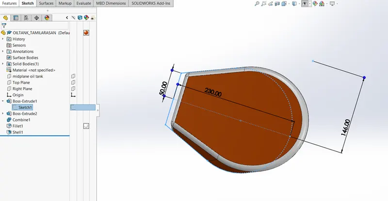
- After doing this select the whole sketch and mirror them about the construction line
- In features tool-Extrude the sketch blind 166mm.
- Now sketch on the midplane the one end of the line draws a straight line vertical 166mm and on the other end draw a 42mm line.
- Give the angle relation between the horizontal line and the right vertical line 92.5mm and then draw a spline on left end of the vertical line to right end of vertical line.
- In feature tool- Extrude this sketch through all in both direction and on insert use the combine feature to combine them and fillet all the edges 10mm.
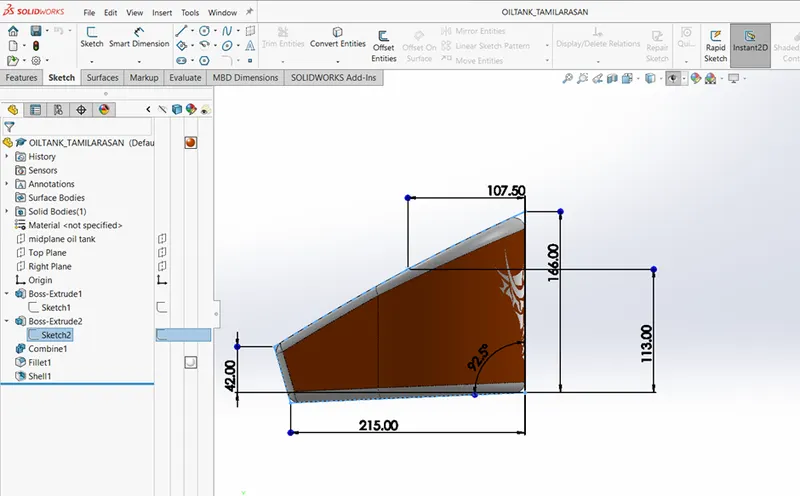
- Create a shell of 3mm for hollow tank.
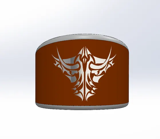
- Apply an appearance white on the fillet area and Siena on the oil tank.
6.CHAIN:
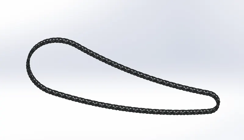
- A chain is connected of loop link made of several small plates and pin joints to make a power transmit from one shaft to another shaft.
- The main advantage of chain is high power transmission capacity with good flexibility
TOOLS FEATURES USED WHILE DESIGING
SKETCH TOOLS:
- Line
- Circle
- Arc
- Trim entities
FEATURES TOOLS:
- Extruded Boss
- Fillet
- Make and save blocks
- Mirror
- Curve driven pattern – tangent to curve
- Appearance
PROCEDURE FOR MODELLING:
- Create a new document and Rename the Front, top and right plane as Mid, Centre and Front plane chain.
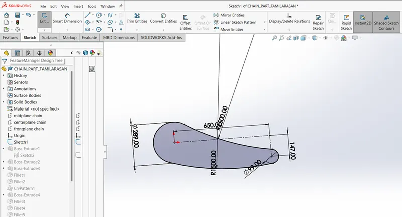
- Start sketch on the Midplane create a construction line 650mm from the origin and draw another construction line 147 mm vertically below the horizontal line make them perpendicular
- Create a circle on both a side of the line 289mm and 99mm then draw a two 3-point arcs of same dimension and make then tangent on both a side of the circle.
- Trim the inner side unwanted circle lines and dimension the both arc 1500mm and keep tangency at the point.
- Sketch the link plate with appropriate dimension and extrude the plate of 15.13 mm line and draw a 2 circle on the both end inner 8 diameter and outer circle is 12 diameter and joint then by arc radius of R28 make tangent to each other and save as link 1
- Sketch the second link plate with appropriate dimension and extrude the plate of 15.13 mm line and draw a 2 circle on the both end side 8 diameter and 12 diameters connect the circle by line and trim the unwanted lines and save as link 2.
- Extruded the both link plates value of 2mm and fillet the sharp edges of pins with value of 0.5mm
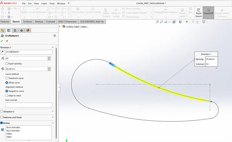
- Select linear patten-curve driven up to the next tangency point of the chain path and import the saved link blocks and repeat the process of pattern for all smooth transition of chain link.
- Make all the pin and plate in separate folder and name then pins and plates in the feature tree.
- Select the pins and plates folder and mirror then for perfect chain link .
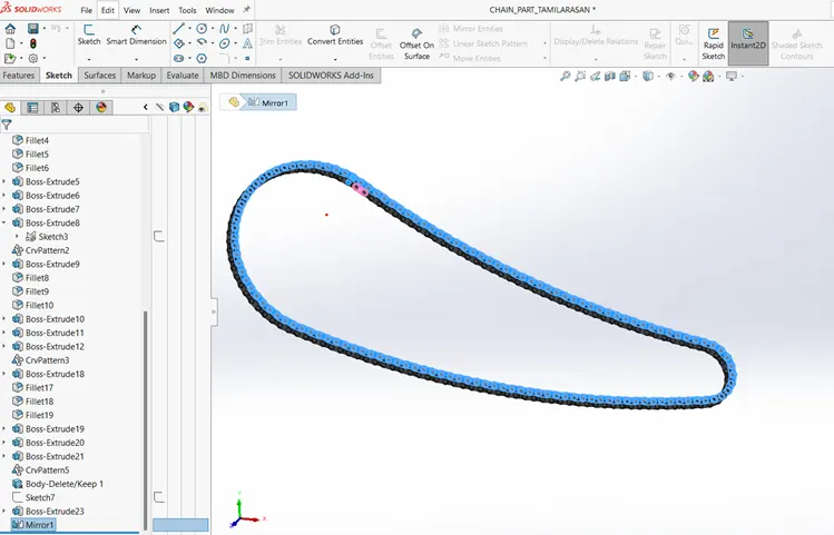
- Apply appearance >chromium plate
7.PEDAL:
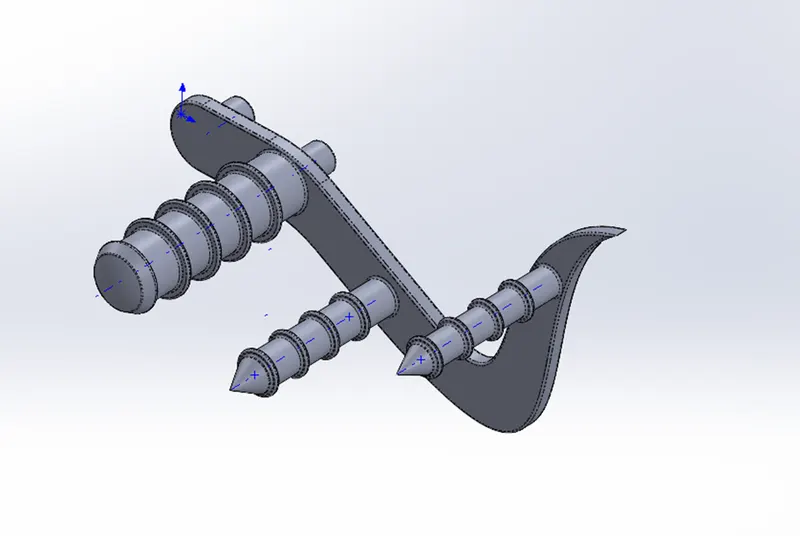
- In chopper motorcycle the Pedal is placed in forward position such tht the legs of the rider are fully extended in a comfortable manner
- Pedal is used by the rider for braking and gearing purpose in motorcycle and the brakes and the gear shift pedals are mounted on each of the pedals
TOOLS FEATURES USED WHILE DESIGING
SKECTH TOOLS:
- Line
- Circle
- Spline
- 3-point arc
- Sketch fillet
FEATURES TOOLS:
- Extruded boss
- Revolve
- Chamber
- Fillet
- Dome
- Linear pattern
- Appearance
PROCEDURE FOR MODELLING:
- Select a new document and select front plane to sketch construction line and midpoint line vertical at the origin.
- Create a for construction horizontal line on both side of the vertical line than create a 72mm horizontal line on both sides then create a profile by using circle and spline feature shown like in the below picture.
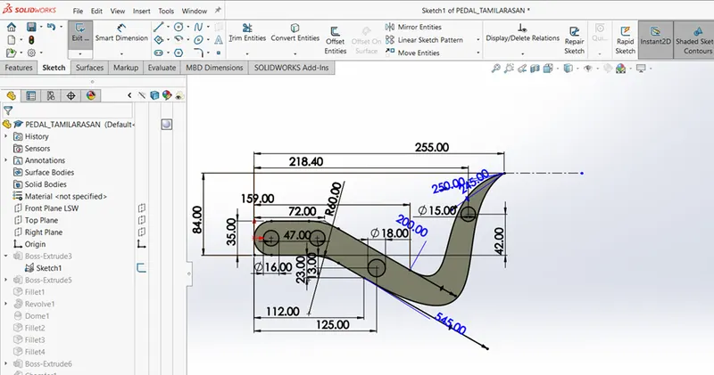
- Extrude the both sketch 1 extrude in blind direction 8mm and sketch 2 selected the contours
- circle to extrude in blind direction 20mm.
- Create a fillet 1mm in both outside face and inner side face on the first extrude.
- Select the top plane for sketch the revolve part as shown in below figure. And revolve the whole sketch 3 by using axis of revolution in direction bind 360 degrees with merge result.
- Use the dome 3mm on top face of revolve and fillet sharp edges of revolve 1mm as well as on the two back side edges.
- Then extrude the sketch 1 face plane and select the circle region 1 and 2 distance of 100.mm.
- Use the Chamber option and select the distance -distance type D1- 16mm and D2-9mm.
- Extrude boss the sketch with the offset 20mm from the surface blind 2.5mm and fillet the face with 1mm.
- Then use the linear pattern with spacing between instance as 20mm and 4 number of instances.
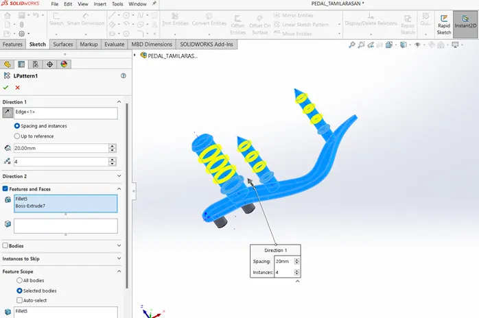
- Apply an appearance >chromium plate to the entire part.
8.FRONT WHEEL:
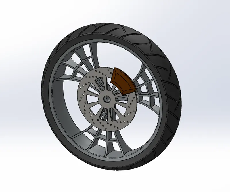
- In American chopper motor cycle, the front wheel always larger than the rear wheel with narrow section as compared to the latter.
- Wheel consists of the rims and the Tyre which make it the component that makes connection between the motorcycle and the ground.
- The wheel is fixed in the Front fork which can be controlled by the rider.
- The rim is an important strength component which ensures safe load carrying capacity of the bike. It should have high compressive strength so as to ensure safety while moving.
- The tyre is made up of rubber to ensure flexibility and bump absorption and it contain treads for grip to the road while riding.
- The tyres have a narrow section meaning narrow surface contact.
- The wheel also houses a Disc brake rotor and its calliper for braking performance.
TOOLS FESTURES USED WHILE DESIGING
SKETCH TOOLS:
- Line
- Circle
- 3-point arc
- Sketch fillet
- Splines
- Trim
- Extend
- 3-point centre rectangles
FEATURES TOOLS:
- Revolve boss
- Extrude boss
- Extrude cut
- Revolve cut
- Circular pattern
- Combine
- Fillet
- Chamber
- Appearance
PROCEDURE FOR MODELLING:
- Create a new document file and select afront plane then create horizontal line of 110mm in origin.
- Create vertical line 40mm on the both ends of the mid-point line and create a horizontal line of 140mm above the origin 330mm and make the vertical relation between both mid-point lines to the origin.
- Create a vertical line on the both ends of the upper line and create a 3-point arc R230 and connect it mid-point to horizontal line mid-point in the distance of 28mm to close the sketch with lines. As shown in figure.
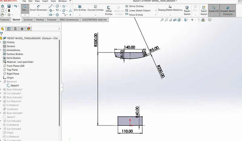
- Revolve the fully defined sketch about the line on origin as axis of revolution on direction blind 360 degree.
- Then select a right plane to create a spoke in sketch as shown in figure below using spline and 3-point arcs.
- Create a fully defined sketch for Extrude boss and then create 4 splines for Extrude cut which will look like spider web profile with the help of 3-point arc (R200, R75, R20 and R15) as shown in figure.
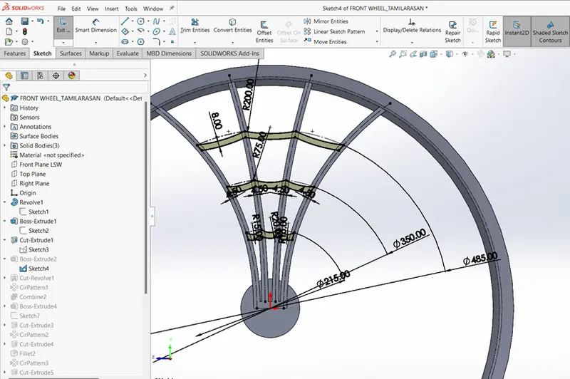
- Create a offset spokes 4.5mm inwards and trim the external line and then Extrude the sketch plane up to vertex option D1 and D2 to create a cob web arcs.
- Create a new sketch on the front plane to convert using intersection surface inner face of rim on the sketch.
- Then combine the spokes and spider web with in the revolved rim and fillet 4mm the front and back face of the spokes.
- Select the right plane for disc brake rotor sketch a circle D345mm and Extrude it offset 45mm and blind D1-7mm and deselect the merge result.
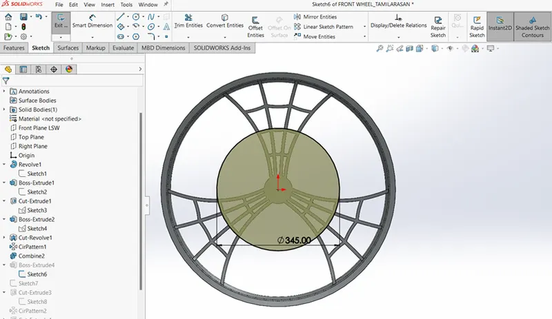
- Create a sketch vertical line 160mm above the origin on the disc then create a ventilation hole.
- Use circular sketch pattern with 14 instances about the disc centre for Extrude cut the sketches by using up to next.
- Select the same disc face for slot cuts, then sketch 2circle about the origin with D100mm and D240mm, sketch the vertical line to connect the both circles.
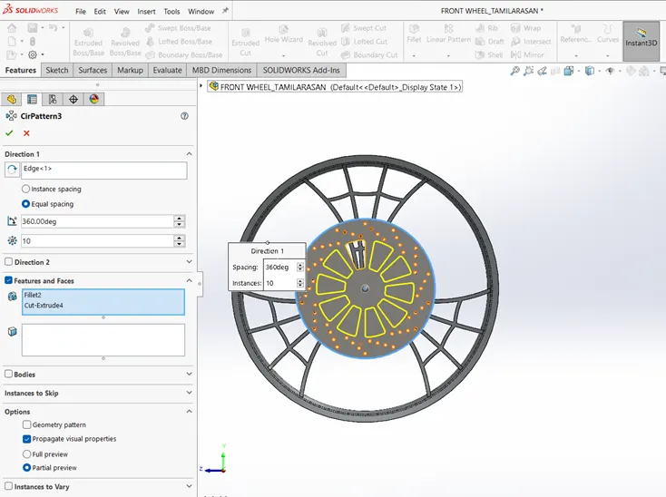
- Trim the outer line to create a fully closed sketch and then extrude cut the sketch up to next.
- Use circular pattern with10 instance about the origin.
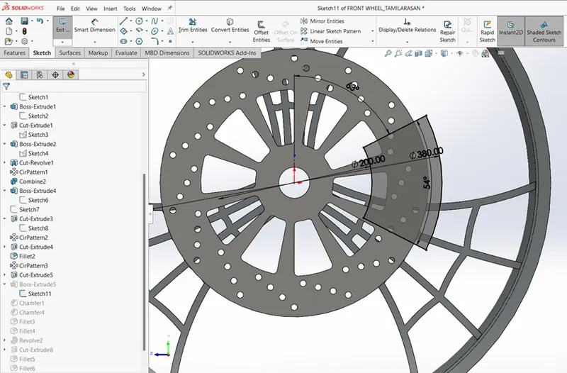
- To create a calliper sketch 2 circles on the disc D200 and D380 and sketch 2 line intersecting the both circles then trim the extra lines.
- Extrude the sketch D1-19.5mm and D2-10.5 do not merge result and chamfer the both face of calliper by distance-to-distance option D1-6mm and D2-20mm.
- Select a Front plane and convert entities with intersection curve and delete the bottom line.
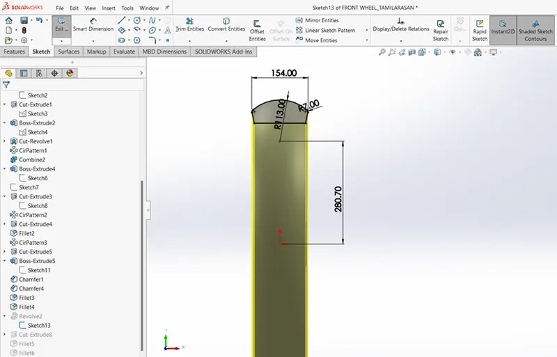
- Create a3-point arc radius of 113 and connect the both end by line make then fully defined and give dimension 280.70mm between origin and 3-point arc.
- Revolve the sketch about the right plane centre axis line and don’t merge result, tyre shown below in below.
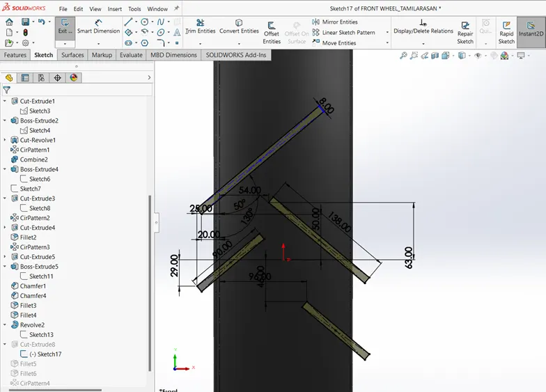
- Create a Extrude cut on front plane by sketch 2*3 point rectangle of D138mm*8mm and another rectangle of D90mm*D8mm.
- Extrude cut the entities sketch offset 450mm and offset from the surface of tyre face 4mm and revolve the feature and see the preview for appropriate cuts.
- Then use the circular pattern for the tread cuts around the hub with 14 instances.
- Apply Appearance:
- Calliper-Siena appearance
- Rims-chromium plate
- Disc-chromium plate
- Trye-Matte rubber
9.REAR WHEEL:
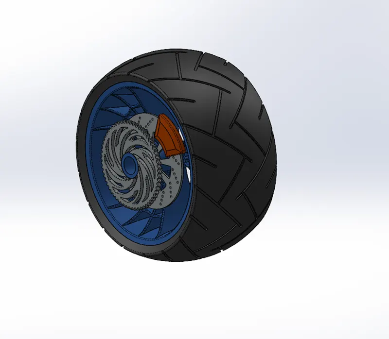
- In American chopper the rear wheel is smaller than the front wheel in diameter but having broad section as compared to the latter.
- Tyres having broader surface contact, heavy load carrying capacity and greater grip of braking system.
- It is consisting of the Rims and tyres which make it the component that make connection between the ground and motorcycle.
- The rear wheel also houses a Disc brake rotor and its calliper and chain sprocket to drive the wheel using power transmitted from engine.
TOOLS FEATURES USED WHILE DESIGNING
SKETCH TOOLS:
- Lines
- Circle
- Splines
- Sketch Fillet
- Trim
- Extend
- 3-point rectangles
FEATURES TOOLS:
- Revolve boss
- Extrude boss
- Extrude cut
- Revolve cut
- Circular pattern
- Combine
- Fillet
- Chamfer
- Appearance
PROCEDURE FOR MODELLING:
- Select a front plane and sketch a horizontal mid-point line of 300mm and sketch a vertical line on the both ends 45mm.
- Draw a horizontal line about 320mm which is placed above the origin 273mm and make its midpoint vertical relation to the origin.
- Create a 3-point arc and make sure that the end point is have horizontal relation with each other and give the angle relation of 75 degree to arc and vertical line
- Give mid-point relation 40mm to horizontal line and arc then fillet of 5mm on both the end of vertical lines.
- Make sure the sketch is fully defined and revolve the sketch about on origin.
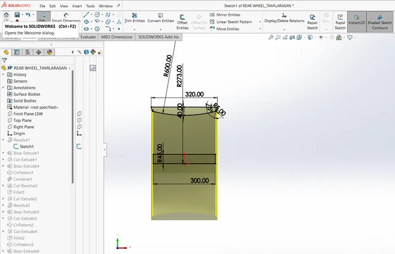
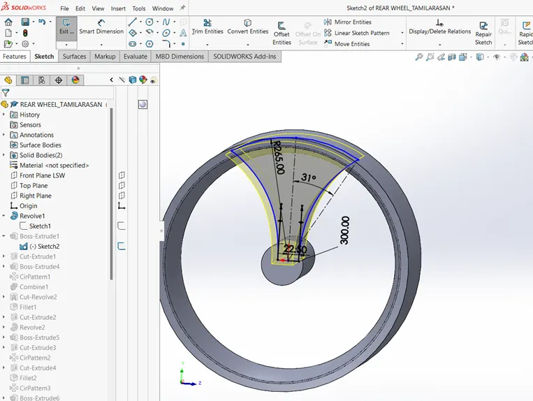
- Select the right plane to create a sketch for spokes with the help of spline,3-point arc and construction line.
- Sketch from the origin create a spline and construction line having angle relation 31 degree in horizontal line 22.5mm. mirror the spline about construction line.
- Extrude the fully defined sketch using midplane D1-300mm and don’t merge result.
- Select the right plane to sketch a 4 spline to create a extrude cut for spokes and extrude cut through all both and select the feature scope and assign only the required body to cut.
- Again, sketch on the right plane to create a cob web arc with the help 3 circle about (D194, D298 and D403) and 3-point arc about (R75, R25, R20 and R15) inward offset the spokes 4.5mm.
- Extrude the sketch plane by select the up to vertex for both the direction 1 and 2, then use circular pattern for 3 as the number of instances.
- Combine the spokes and cob web with the revolved rim and convert using intersection surface the inner face of the rim. And create a revolve cut the sketch about the centre line and select only required body.
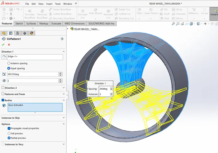
- Apply 3mm fillet on the both front and back face of the spokes.
- Create a sketch to Axle for rear wheel and revolve the sketch about the 90mm line
- Select a right plane and sketch a circle of D330mm, extrude it offset 105mm and blind D1-7mm and don’t merge result.
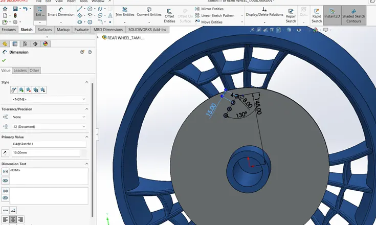
- Sketch a ventilation holes 145mm vertical to the origin on the face of disc and use circular sketch pattern with 16 instances about the disc centre and fully define the sketch and extrude cut the ventilation holes.
- Sketch 2 circle of D90mm and D255mm about the centre of the sprocket face and sketch a circle of 203mm place it 35mm above origin. Place 2 Arc intersecting the circle and 12 parts.
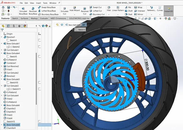
- Trim the extras and extrude cut the sketch up to next.
- Use circular pattern of 6 instanced cuts about the centre of sprocket.
- Select the front plane to model the tyre of rear wheel and convert entities with intersection curve and delete the bottom curve
- Sketch a line to connect the end points of arc to converter entity on the rim top and keep vertical distance between origin and arc end point 303mm.
- Revolve the sketch about the right plane centre axis line and don’t merge result.
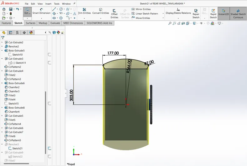
- Create a sketch on front plane 2*3 point rectangle of D280mmm *8mm and sketch 2 more rectangle of D97mm*D8mm.Sketch another 2-rectangle perpendicular to the left tread as shown in figure
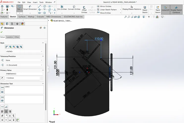
- Extrude cut the tread sketch offset 400mm and use offset from surface of 8mm.
Appearance;
- Calliper-Siena
- Rims-chromium plate
- Disc-chromium plate
- Sprocket-chromium plate
- Tyre-matte rubber
10.FORNT FORKS:
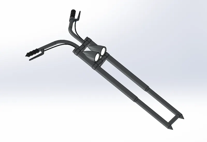
- The front forks of this American Chopper motorcycle have a high rake angle of 59 degree and a trail of nearly 650mm.
- Front forks is efficient design helps in better ride and handling of the motorcycle and it can the function mechanical work of front wheel and also control the braking and gearing system.
- It also houses various sub component such as headlight, handle bars, handle grip, triple clamps, brake lever, clutch lever, cables and axle.
- It is consisted of front suspension component which is generally called telescopic forks.
TOOLS FEATURES USED WHILE DESIGING
SKETCH TOOLS:
- Lines
- Circle
- Spline
- 3-point arc
- Trim
FEATURES TOOLS:
- Revolve boss
- Extrude boss
- Linear pattern
- Extrude cut
- Revolve cut
- Dome
- Body move/copy
- Curves-projected
- Sweep
- Reference geometry
- plane
- Mirror
- Combine
- Fillet
- Chamfer
- Appearance
PROCEDURE FOR MODELLING:
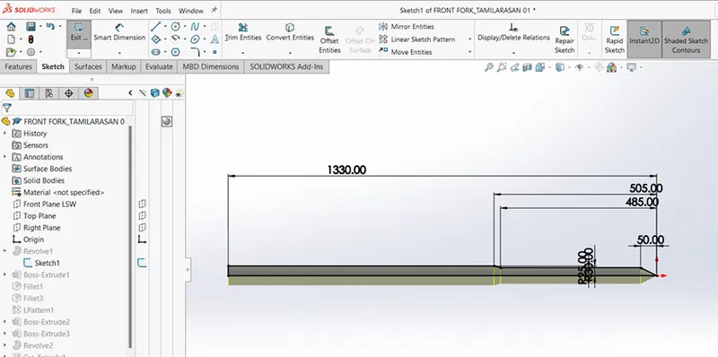
- Select the front plane and start sketch the 2D profile with the help of line features .
- Exit the sketch and start revolve the 2 D sketch about the 1330mm line and select the top face to sketch the circle of D75mm. as shown in below figure
- Confirmed the sketch is fully defined than extrude the sketch from offset toward the fork 20mm and D-40mm and don’t merge the result. And 5mm fillet the all edges of created sketch.
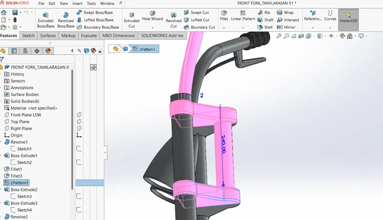
- Use the temporary axis and use linear pattern for the triple clamp with 2 number of instances at 240mm distance
- Select a front plane to sketch the headlight bucket as shown in figure.
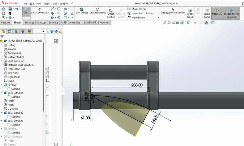
- After complete the fully defined sketch for headlight bucket then revolve it about the line direction blind and don’t merge the result and create a dome on headlight lens of 7mm as shown in above figure
- Select the top plane to sketch the handle bar create a circle D30mm on the face of triple clamp and use spline and line feature with tangent relation.
- Use projected curves option and create a curve from above 2 sketch and sweep the circle on the curve path to create a handle bar.
- Select a reference plane at the handle bar end to sketch a handle grip and revolve the sketch about the 145mmline and give select to merge result with clamp only as shown in figure.
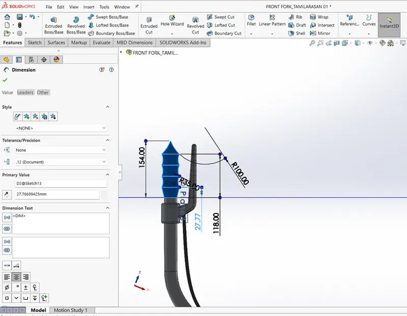
- To create a Brake lever, create a new plane with plane 1 as reference at an angle of160 degree and sketch on the plane 2 then extrude the sketch midplane with D1-15mm and give merge result only with the handle bar and fillet all the edges appropriately.
- Then after complete the 2 sketches for cable and use projected curve. Mirror the whole front fork about flat face of triple clamp and combine the bodies as shown in figure.
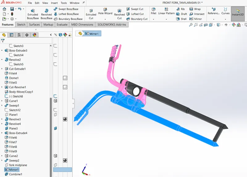
- Apply appearance
- Headlight bucket - chrome plate
- Forks - chrome plate
- Triple clamp - chrome plate
- Handle bar - chrome plate
- Handle grips & cables - glossy rubber
- Headlight lens - white area (light)
11.CHASSIS:
- Chassis gives a structural framework of all automobiles and it carries all the other component of automobile.
- It has to be the strongest components of any vehicle as it is the base structure so it should be made up of high strength material that can withstand variable compressive, tensile and shear stresses.
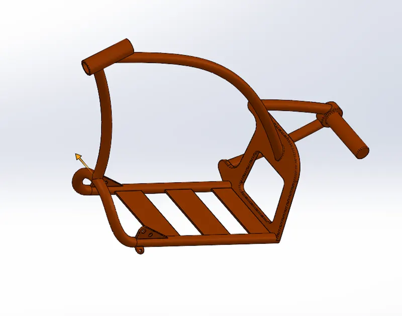
- In American chopper motorcycle the chassis is a rigid hardtail frame chassis which excludes the rear suspension component.
TOOL FEATURES USED WHILE DESIGING
SKETCH TOOLS:
- Lines
- Circle
- Splines
- Trim
- Sketch picture
FEATURES TOOLS:
- Revolve boss
- Extrude boss
- Revolve cut
- Extrude cut
- Dome
- Reference geometry
- Mirror
- Combine
- Fillet
- Chamfer
- Appearance
PROCEDURE FOR MODELLING:
- Create a new document and rename the top and front plane as bottom plane chassis and midplane chassis for reference view.
- Select the midplane chassis and place the chopper image for reference the structure and applying as x=930mm and y = -805mm. use transparency as required.
- Now start sketching the midplane chassis by using splines and sweep features as shown in figure.
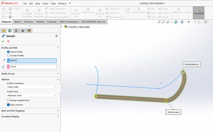
- Sketch a chassis back plate on the right plane and extrude bass the fully defined sketch 22mm away from tube section and merge results. And extrude cut the position on back plate as per chassis.
- Create a hub, axle and dome on hub on the sweep swingarms on the new reference plane.
- Then use split and consume the bodies after the back plate section and create another reference plane for the downtube and create splines as per the sketch picture and sweep the path and give pierce relation.
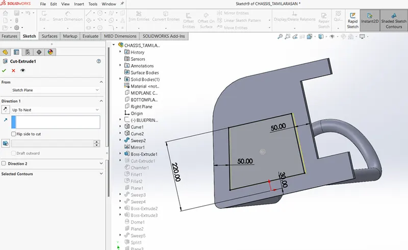
- Cut the unwanted lower chassis parts by using split features.
- To create a base plates sketch on the lower base chassis tube and extrude the sketch up to next option ... as shown in the figure.
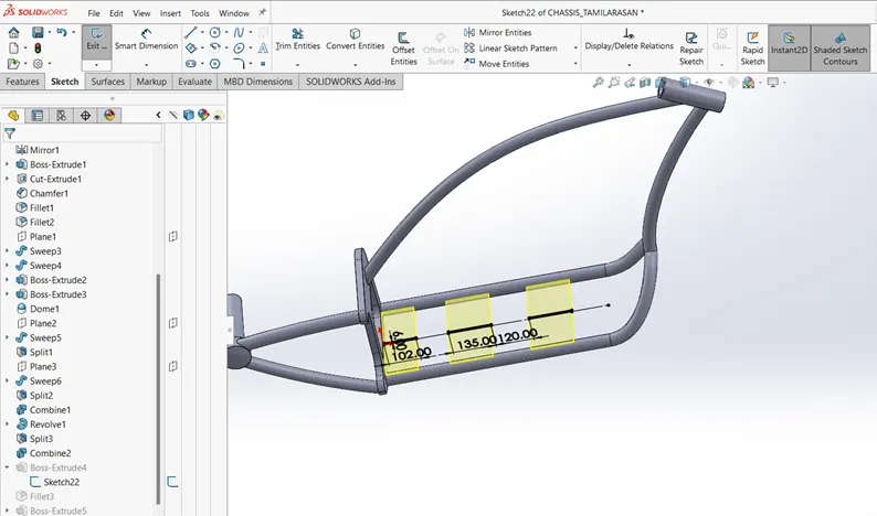
- Then Create a mount for foot peg and kickstand by using extrude boss, extrude cut and apply a fillet and mirror the foot peg mount about midplane chassis, then combine all solid bodies into one as chassis.
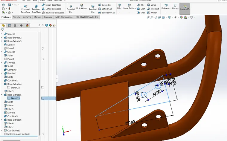
- Apply appearance of full chassis as Siena car painted and save the part.
12.ENGINE
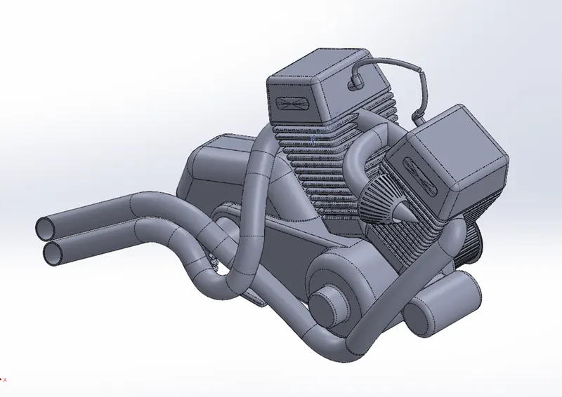
- In American chopper motorcycle we have a V-twin type engine consisting of external air filter, spark plugs on both engine cylinder, transmission pully, air cooling fins starter motor sprocket for chain drive and gearbox.
- Engine is mounted on the chassis and fixed in the lower base stand of chassis.
- It is the powerhouse of automobile consists of piston cylinder arrangement which powers the motorcycle. The Ic engine houses air intake, exhaust outlet and fuel intake ports.
TOOL FEATURES USED WHILE DESIGING
SKETCH TOOLS:
- Lines
- Circle
- Sketch picture
- Splines
- Circular pattern
- Centre point & 3-point centre point rectangle
- Trim
FEATURES TOOLS:
- Extrude boss
- Extrude cut
- Revolve boss
- Dome
- Sweep
- Split
- Curves projected
- Composite curves
- Reference geometry-planes
- Mirror
- Combine
- Fillet
- Chamfer
- Appearance
- Circular & linear pattern
PROCEDURE FOR MODELLING:
- Place the picture reference on the front plane with X = 1493mm and Y = - 965mm and set transparency = 0.50. rename it as blueprint engine.
- select the front plane to create a sketch of base motor and gear box by using the circle and line features make than tangent. then extrude boss midplane option 200mm by selected contours all region .as shown figure.
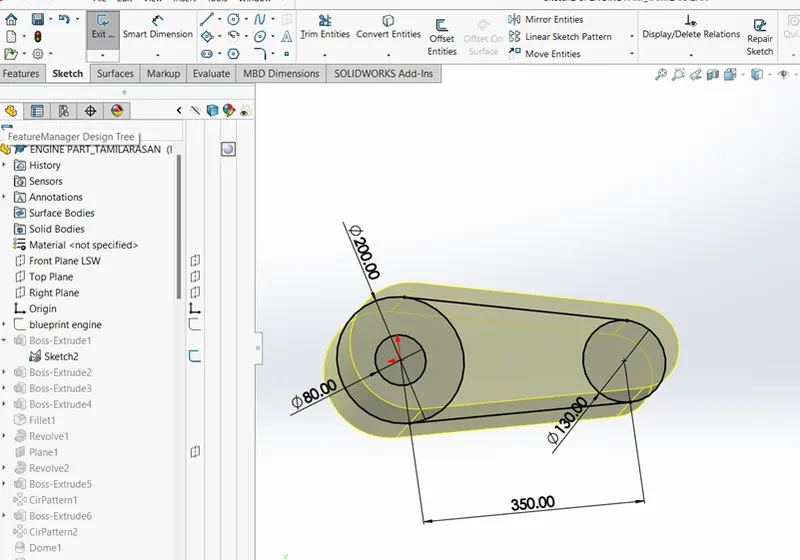
- Then select the right plane to sketch the transmission belt pulley and revolve the sketch and make extrude rectangle on the pulley for grip element for belt and give circular pattern on front pulley and rear pulley and apply dome on the end face.
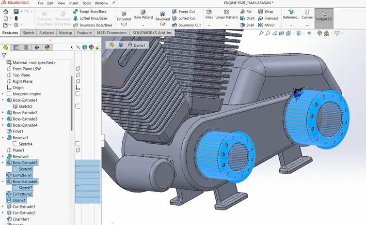
- Sketch for cylinder casing use reference plane and sketch a rectangle on the plane and extrude it like in picture reference. Then provide fine for air cooling purpose by using linear pattern and then create a spark plug and fillet the sharp edges.
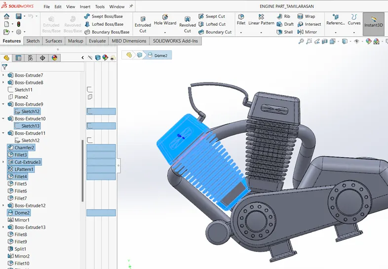
- Use the right plane to mirror the cylinder casing on opposite side as shown in figure.
- to create a front sprocket sketch circle D40mm at the sprocket reference from the picture and extrude the sketch 80mm and sketch sprocket circle and extrude further 15mm
- then create a chain cut by sketch the teeth profile to extrude and chamfer it. use circular pattern make then 21 instances. As shown below.
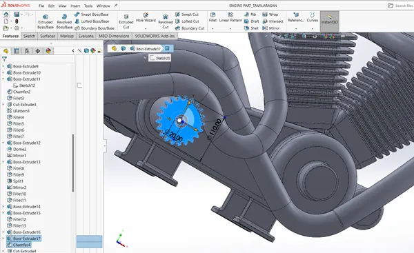
- Select the bottom face of engine to Create a mount on the bottom for the chassis mounts,
- To create exhaust pipes, sketch a spline as per the reference picture and use projected curves, then use split feature to cut out the exhaust ends as look like reference picture.
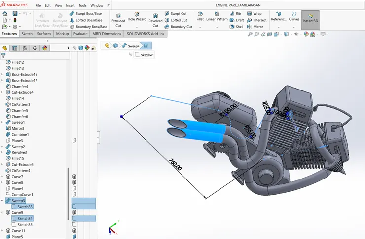
- The air intake manifold is created by using spline and projected curves features.
- Sketch the air filter and revolve the fully defined sketch and use extrude cut then give circular pattern for provide cuts.
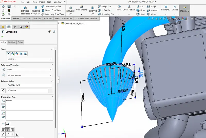
- Apply appearance:
- Engine - polished aluminium
- Spark plugs& cables – gloss black
13.FUEL TANK:
- A fuel tank is a safe container for flammable fluids. It is the fuel storage component of the motorcycle.
- In American chopper the fuel tank is made to house a seat and fit to the chassis centrally with the mount.
- It is connected to the fuel pump or fuel regulator device such as carburettor.
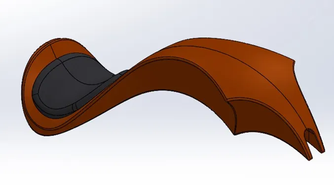
- The fuel tank is made up of these materials steel, iron, or aluminium, which can withstand high temperatures.
TOOL FEATURES USED WHILE DESIGING
SKETCH TOOLS:
- Lines
- Sketch picture
- Splines
- Trim
FEATURES TOOLS:
- SURFACE TOOLS:
- Surface sweep
- Surface loft
- Surface trim
- Surface knit
- Surface Extrude
- Surface boundary
- Curves
- Projected curves
- Split line
- Sweep cut
- Reference geometry- planes
- Mirror
- Fillet
- Shell
PROCEDURE FOR MODELLING:
- Create a new document – Rename the front, top and right to Midplane fuel tank, bottom plan fuel tank and right plane fuel tank.
- Select the mid plane fuel tank and fix the reference picture of motorcycle in X = 2096mm, Y=1096mm and set transparency – 0.50.
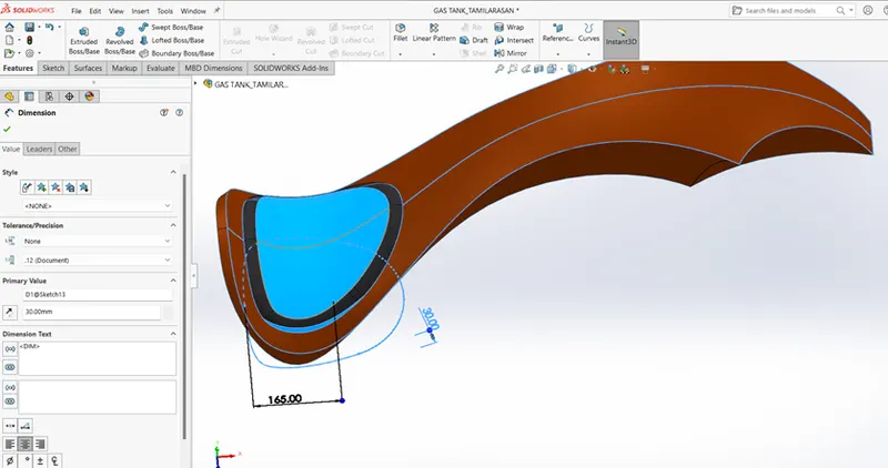
- Select the mid plane fuel tank to sketch a profile of fuel tank by using line and spline features with picture reference. As shown in figure.
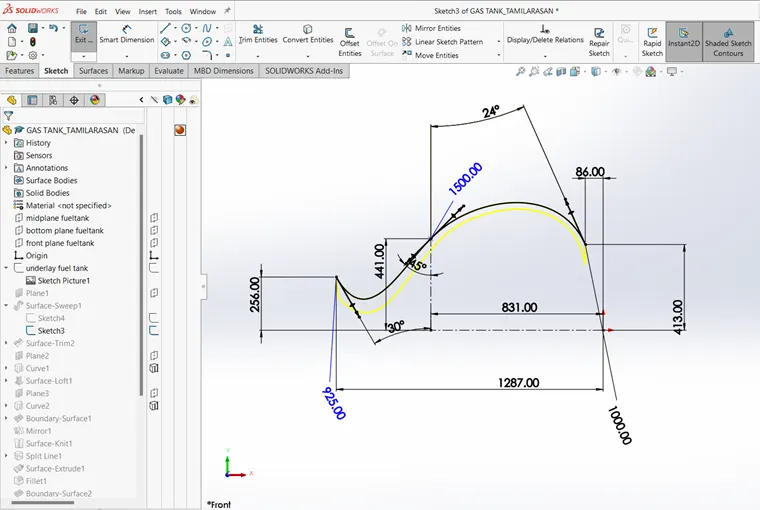
- Use sweep feature to sketch the surface in the direction of mid plane fuel tank.
- Select the bottom plane fuel tank to sketch a spline to create a projected curves as in the reference picture and use surface loft and surface boundary to create the surface model of fuel tank. as shown in the figure.
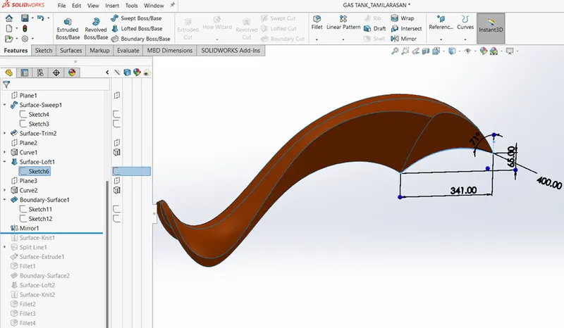
- In bottom plane fuel tank create a sketch for the seat by using surface extrude and fillet the seat sharp edges. And create a shell of 3mm without any selection.
- Apply appearance;
- The Fuel Tank -Siena
- Seat – leather fabric
- ASSEMBLY OF AMERICAN CHOPPER MOTORCYCLE
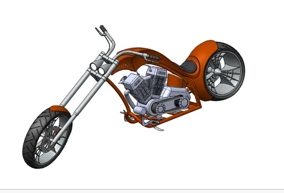
- In Solidworks software the assembly is one of the major steps to complete the modelling. To make the assembly we have to mate then in basic relation between the two components.
- Assembly is useful to give the more realistic outlook of the American chopper motorcycle
- The Solidworks assembly mates consists of 3 main mates they are;
- Mechanical mates
- Standard mates
- Advanced mates
- MECHANICAL MATES:
- Universal joint
- Gear
- Rack & pinion
- Cam
- STANDARD MATES
- Width mates
- distance mates
- angle mates
- coincident
- concentric
- parallel
- perpendicular
- tangent
- ADVANCED MATES:
- Profile centre
- Symmetric
- Path mates
- Linear coupler
PROCEDURE FOR ASSEMBLY:
- In the assembly process first, we have to fix the chassis on the front plane of the assembly coincident to mid-plane engine and give coincident relation to them.
- In assembly use insert component feature to select the engine and mount to the base of chassis 20mm behind the vertical face of plate, make than coincident to each other.
- Then mount the pedal on the chassis with concentric and coincident relation and mirror the pedal also give limit angle.
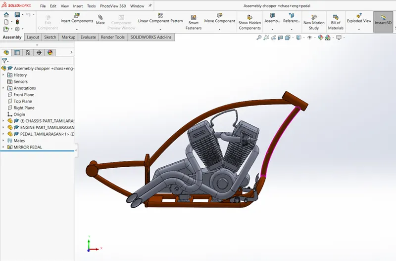
- To mount the rear wheel, we have to give coincident relation to mid-plane chassis and right plane rear wheel and make the axle hole concentric with the hub axle.
- Place the rear fender with concentric relation to rear wheel and also give parallel relation to vertical rear fender and right plane chassis.
- For the transmission belt assembly give width mates, concentric and angle mates on pulleys and the parallel relation to transmission belt top face with the engine top surface face.
- Place the oil tank on gearbox face and give coincident relation with midplane chassis and mid plane oil tank.
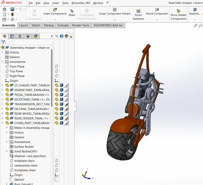
- The front fork concentric to the steering and give width mate on the chassis, give limit angle 30-degree relation to rotation in both directions.
- Fix the chain with rear wheel by giving relation of concentric and width mates, give parallel relation between midplane chassis and mid plane chain.
- Mount the fuel tank by giving coincident relation with midplane chassis and mid plane fuel tank.
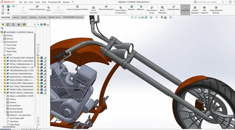
- For front wheel assembly give coincident relation with right plane front wheel and midplane front fork, make the axle concentric to axle hole.
- Finally fix the kickstand with chassis by give some mates relations like concentric and coincident.
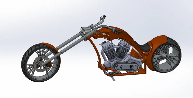
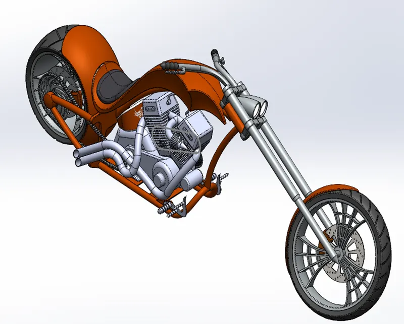
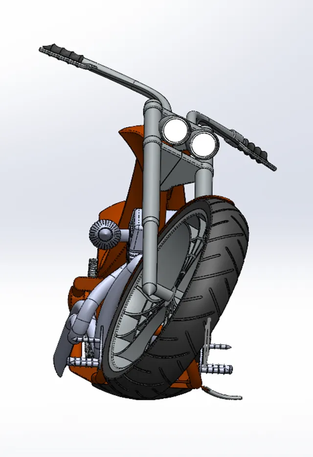
- Place the front wheel, rear wheel and kickstand in top plane of the assembly by giving tangent relation for all of them in rest position to complete the assembly of American chopper motorcycle.
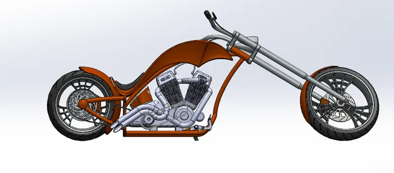
1.FRONT VIEW OF ASSWMBLY:
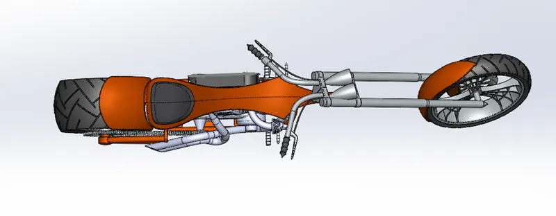
2,TOP VIEW
3.ISOMETRIC VIEW:
3.RIGHT VIEW:
RENDERING OFAMERICAN CHOPPER
- RENDERING:
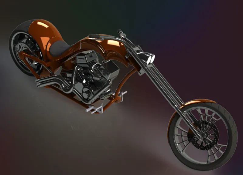
- To make the American chopper realistic we have to create high quality images and graphical appearance in the various environments and lighting back grounds.
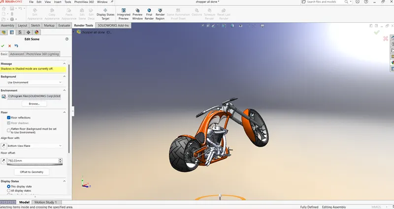
- In Solidworks software for rendering we use photo view 360 features which is in built add in Solidworks.
- RENDERING PHOTO VIEW 360:
- First select the tool tab and search (Add in) commend to active the photo view 360 rendering.
- in photo view 360 it has various features like:
- Edit Appearance
- Edit scenes
- Edit decal
- Preview window
- Render region
- Final render
- Option
- Network rendering
- Final image type
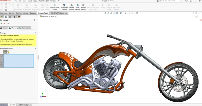
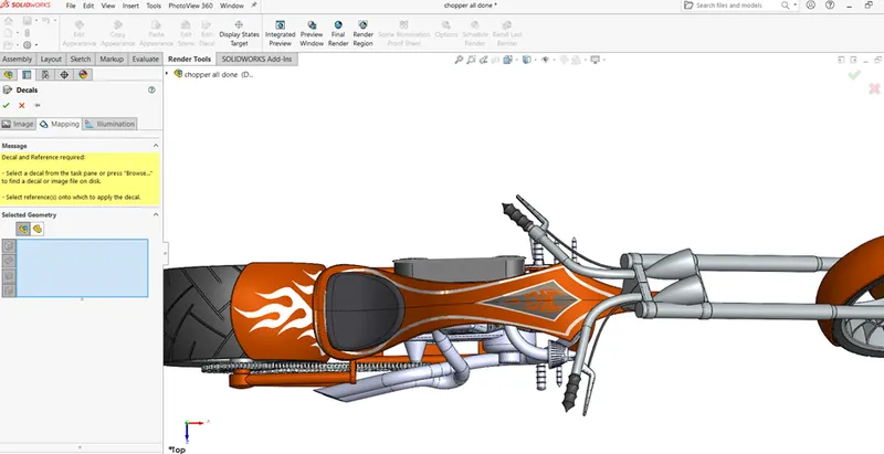
- In Edit Decal we can add image on the component selected surface by mapping value in coordinate direction and select the axis XYZ origin.in illumination select the underlaying appearance for better decal.
DECAL – IMAGE AND MAPPING ( RIGHT VIEW ) :
DECAL -IMAGE AND MAPPING ( TOP VIEW ):
- in photo view 360 we can adjust the lighting of the scene’s setup in camera views by view dropdown
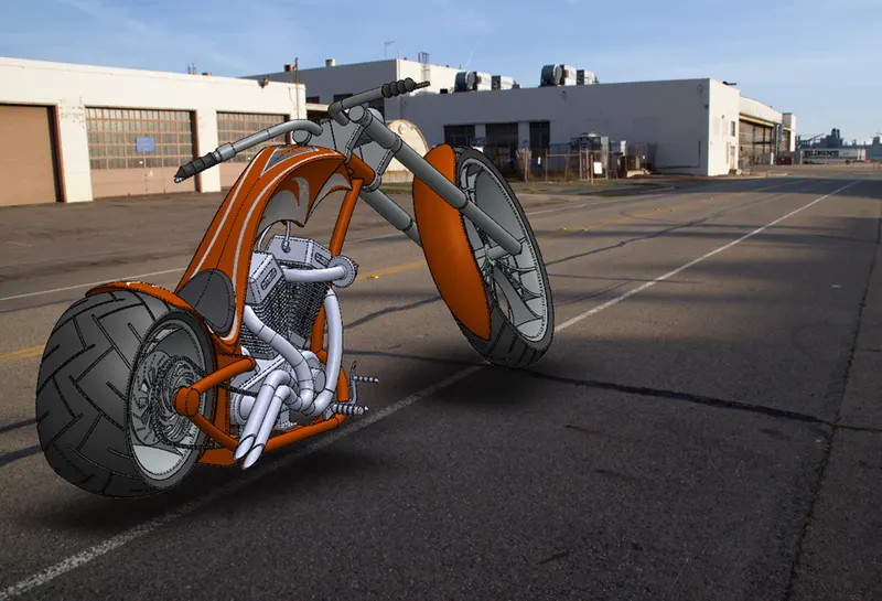
AMERICAN_CHOPPER_RENDER_TAMILARASAN:
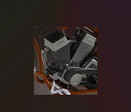
ENGINE_RENDERING REGION_VIEW:
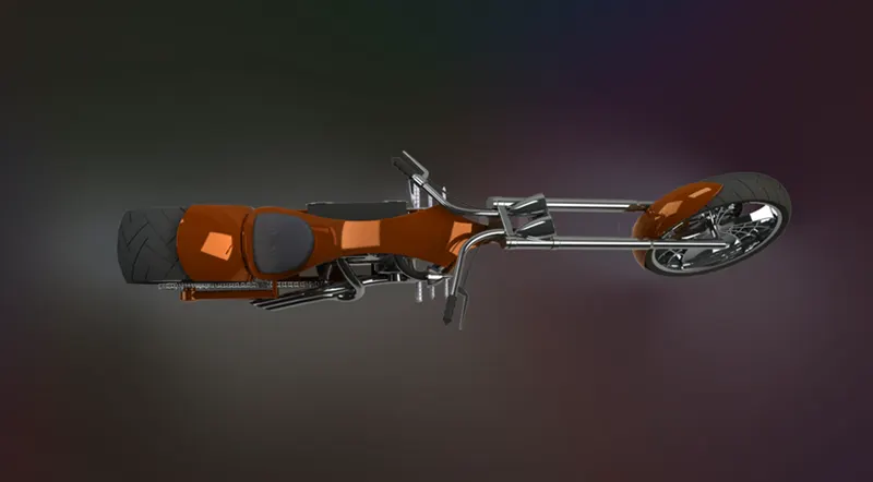
TOP VIEW:
SIDE_VIEW:
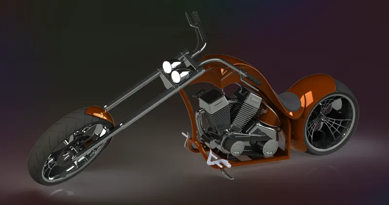
FRONT_VIEW:
ISOMETRIC _VIEW:
CONCLUSION:
- In Solidworks the Parts, Assembly and rendering of photo view 360 of the American chopper motorcycle is successfully completed.