Radar Mast & Final Assembly of Yacht
Title of project = Designing of parts,Assembly and rendering of a model of a Yacht in Solid works.
Objective - To learn and get familiar with the interface and different functions/commands as well as options in Solidworks for Part modelling and the basics-Advance level of sheet metal.
Introduction - A (YACHT) is a type of boat which is mainly used for pleasure, cruising, or racing. It usually has a cabin so it does not need to return to the harbour overnight. Originally, yachts were sailing boats, but now there are also motor yachts. The name comes from the Dutch word jacht means "Hunt", which originally meant hunting-boat or fast boat..
Types of yacht:
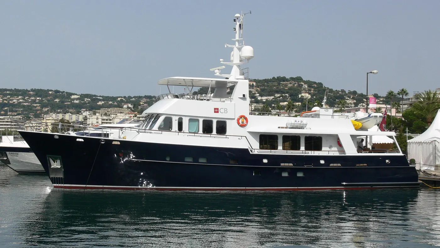
1.Commercial yacht code24m/79ft max 12 passengers.
2.Racing yacht
3.Charter yacht
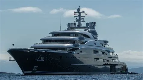
In this project, we have tried to design a cosmetic model of the Yacht. In this we have
designed different components or parts of it like propeller, Hull, Radar,superstructure, radarmast and other parts and assembled it in the end to get a lookalike of the yacht in Solidworks. Solidworks is a computer aided design (CAD) and Computer Aided Engineering (CAE) program. It is published by assault systems and is used largely in the manufacturing space by companies all over the world. We have used solidworks to design different parts of a model of the Yacht and assemble and render images of it in the end.
Design methodology/Approach
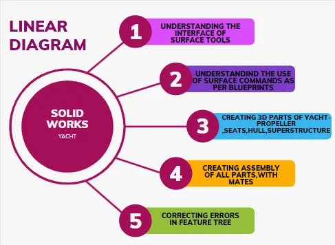
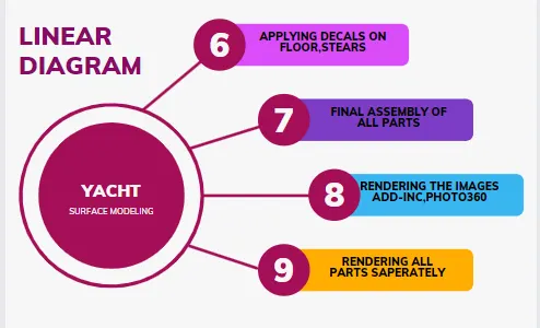
Description along with images of part files-
The basic tools used were
Sketch
1. Smart dimensions - It helps applying dimensions to the entities easier and making the sketch fully constrained.
2. Convert entities - helps projecting entities from a different plane to the current sketch plane.
3. Offset entities - creates an offset for the selected entity.
4. Trim entities - Deletes selected parts of the sketch.
5. Mirror entities - Creates a similar pattern about the selected plane.
6. Linear and Circular pattern - Creates a linear or circular pattern of the selected entity about the selected plane or axis.
• Features
1. Extruded surface/boss/base/cut - Creates a solid body for the sketch in the defined direction.
2. Revolved surfacc/boss/base/cut - Creates a solid revolve, mainly used for creating circular rods.
3. Swept surface/boss/base/cut - Creates a solid surface along a given curved profile
4. Lofted surface - creates a lofted surface along three references.
5. Fillet - Creates a fillet along sharp edges of the given radius.
6. Shell - Creates a hollow inside a solid block.
7. Combine - Merges two solids after the extrude is done.
ADVANCED TOOLS WITH PART IMAGES:
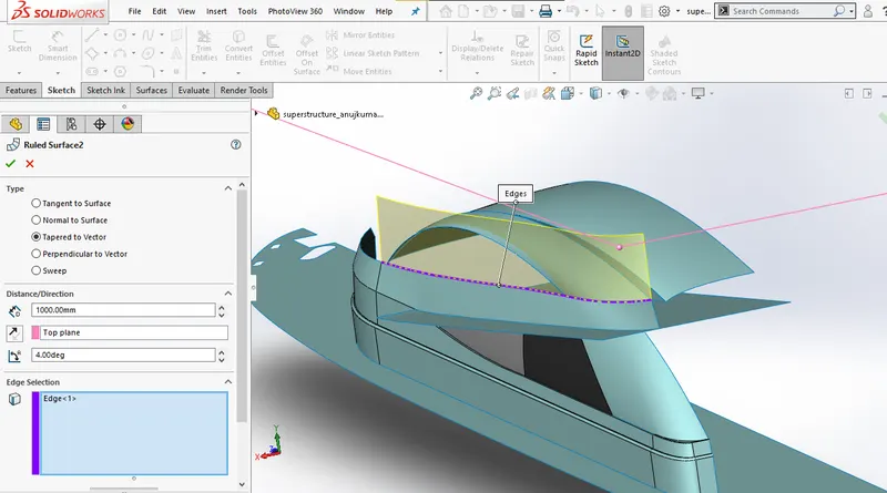
1.RULED SURFACE WITH DIRECTION
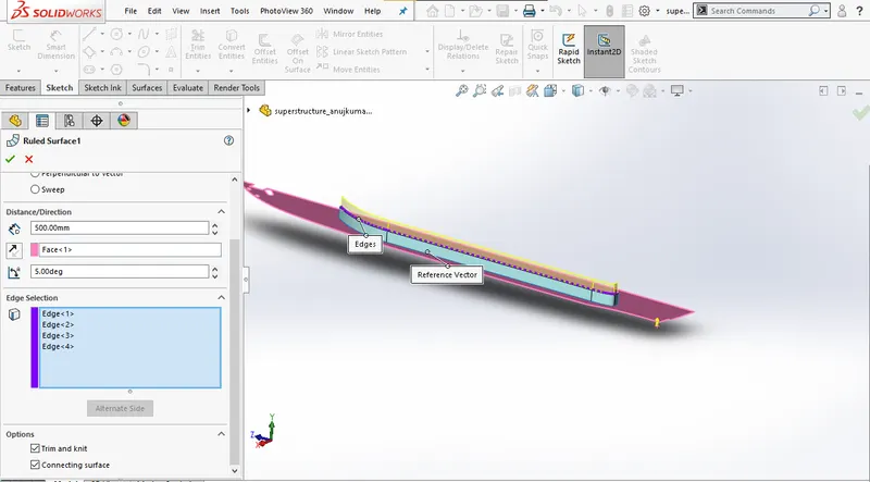
2.RULED SURFACE ALTERNATE SIDE
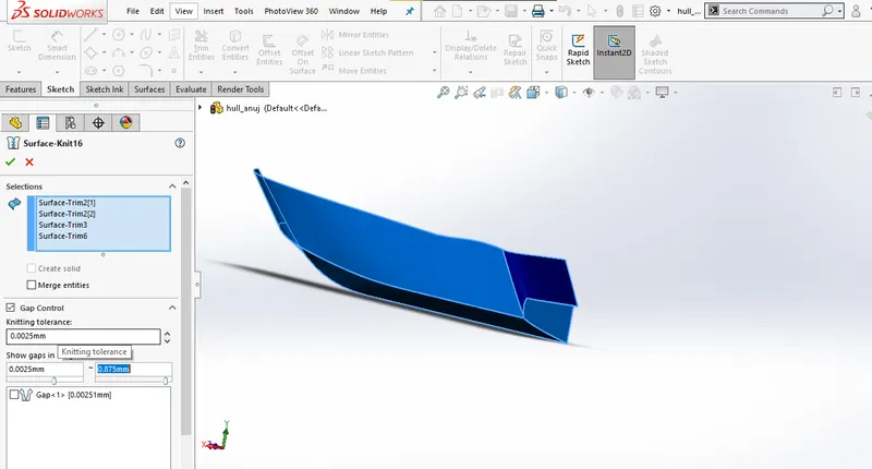
3.SURFACE KNIT
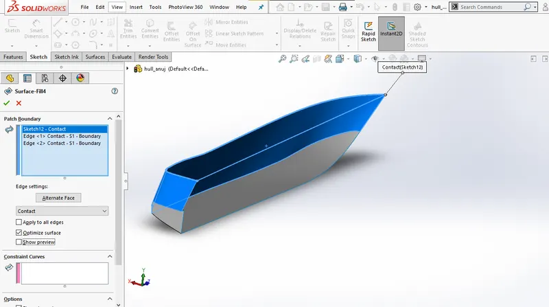
4.SURFACE FILL
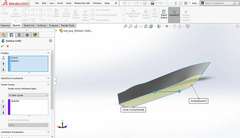
5.SURFACE LOFT
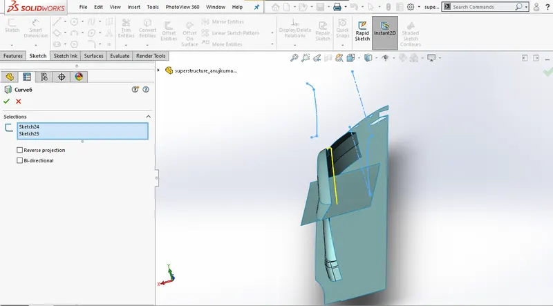
6.PROJECTED CURVE
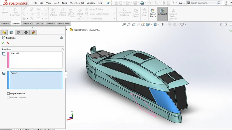
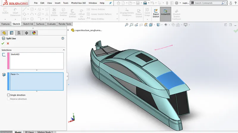
7.SPLIT LINE
8.SURFACE TRIM
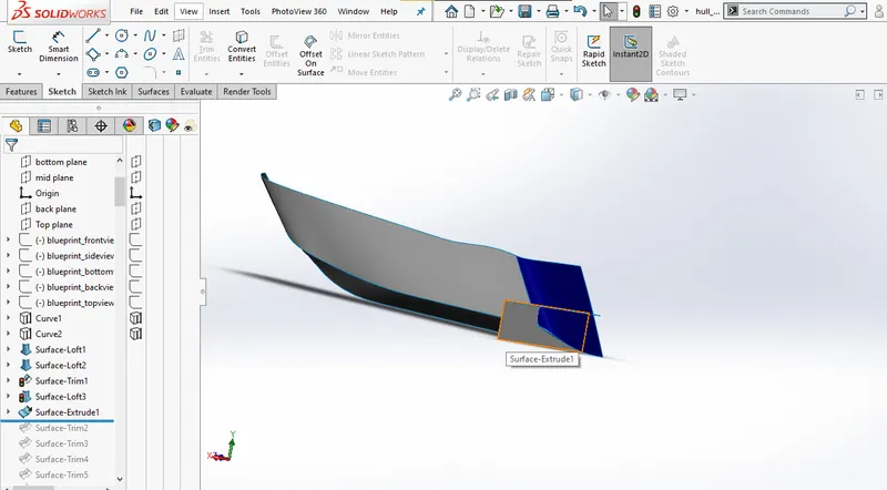
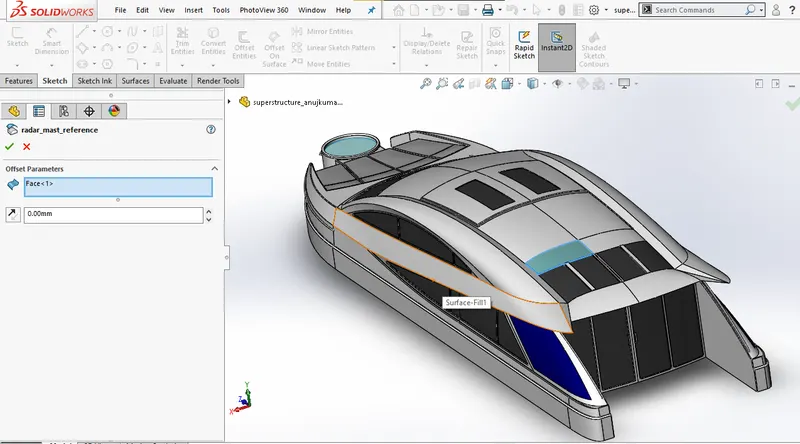
9.OFFSET SURFACE USE FOR APPLYING DECAL,FOR OTHER PART REFERENCE.
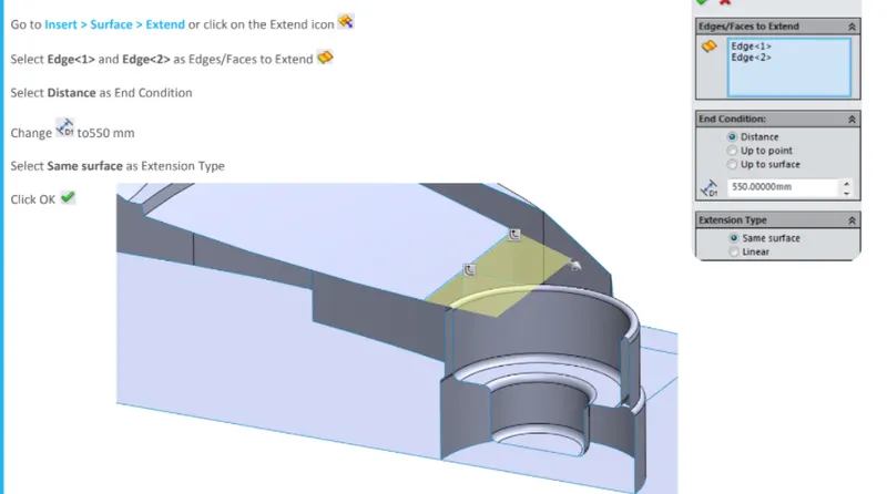
10.EXTEND SURFACE
5 ASSEMBLY IMAGES
1. RIGHT SIDE VIEW
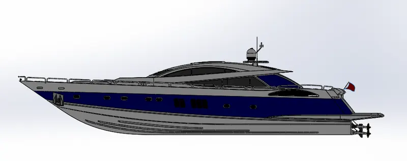
2.TOP VIEW
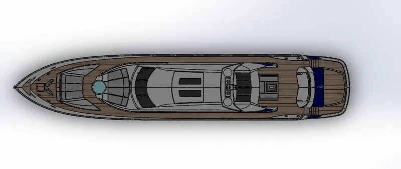
3.ISO VIEW
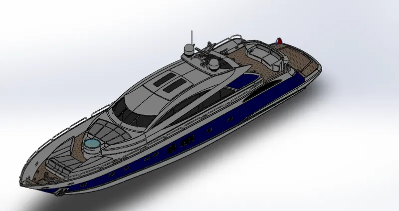
4.BOTTOM VIEW
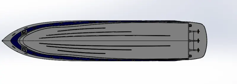
5.FRONT VIEW
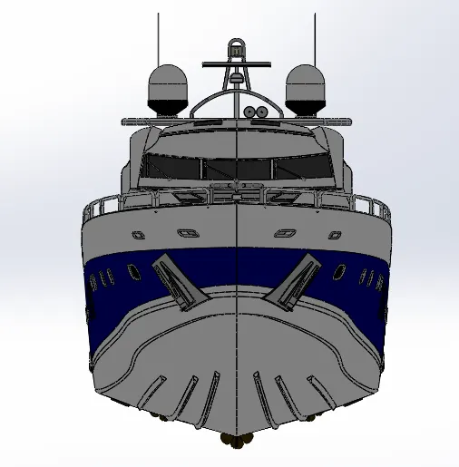
6.BACK VIEW
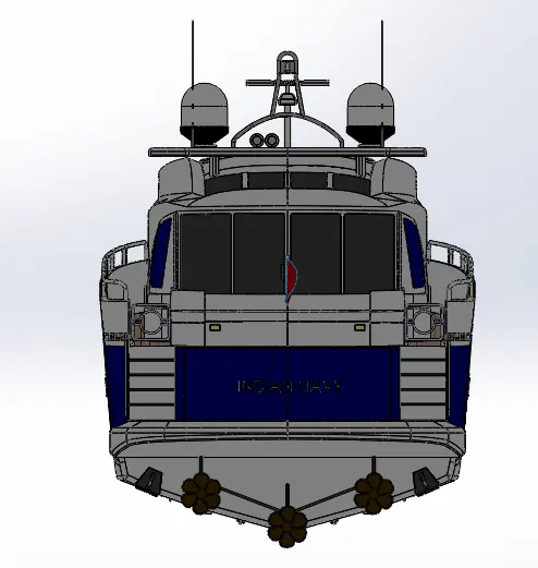
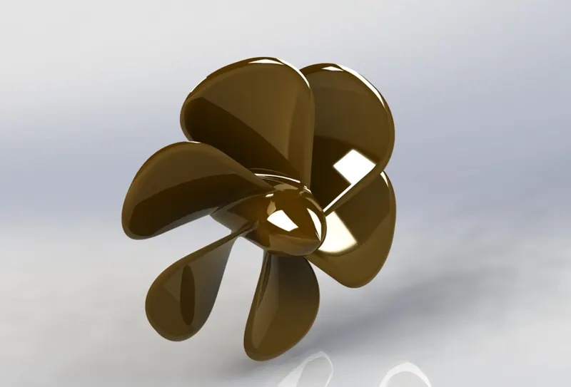
RENDERING IMAGES:
1.PROPELLER
2.REDAR
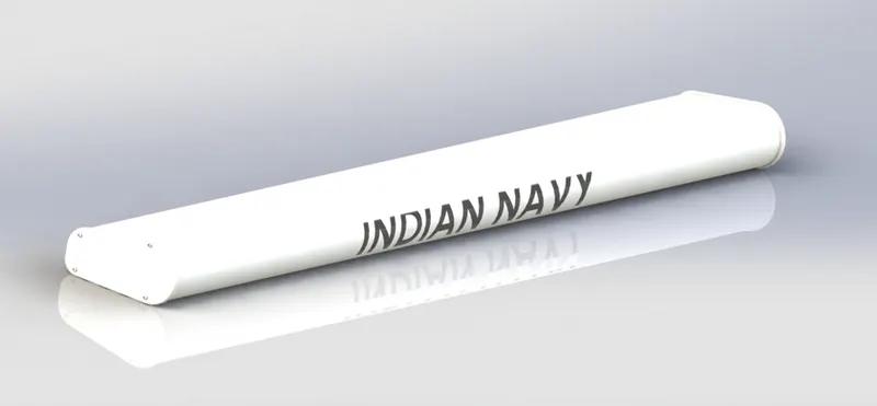
3.RADAR MAST
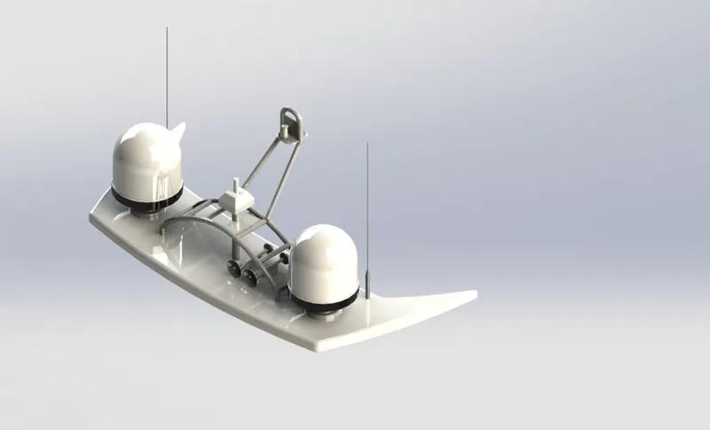
4.FRONT SEAT
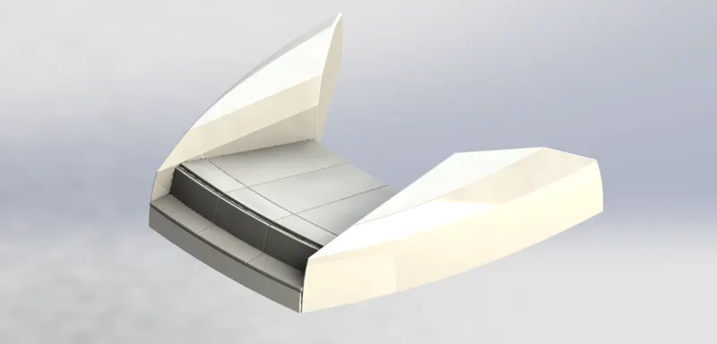
5.HULL
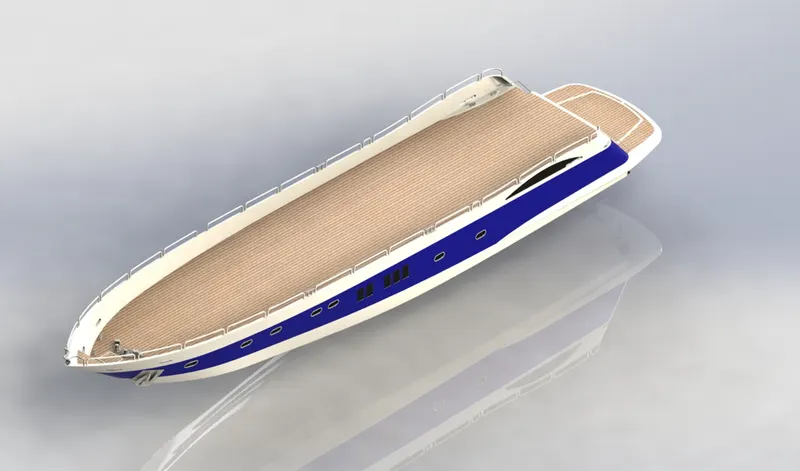
6.GARAGE DOOR
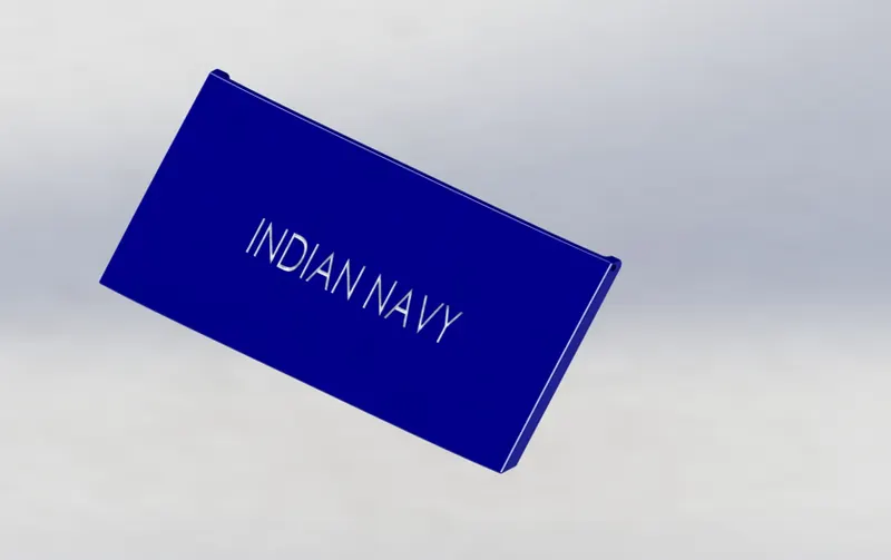
7.REAR SEAT
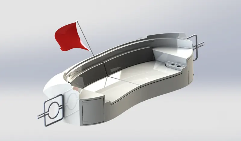
8.MIDDLE SEAT
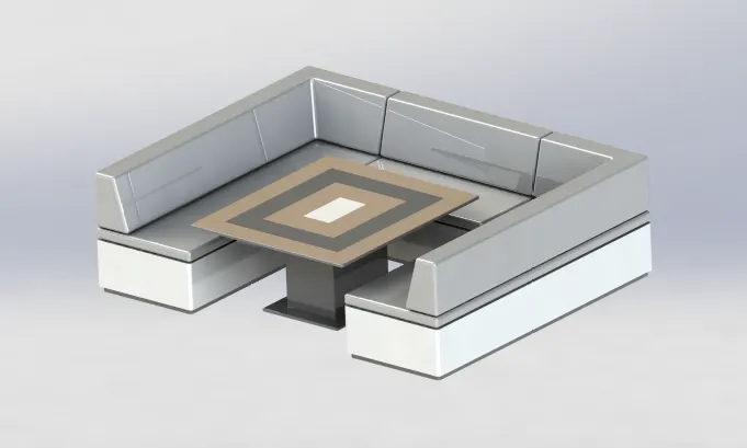
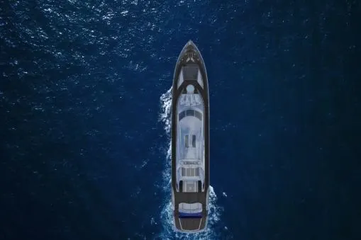
9. ASSEMBLY
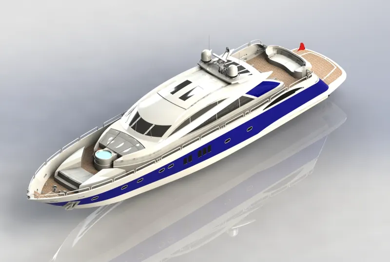
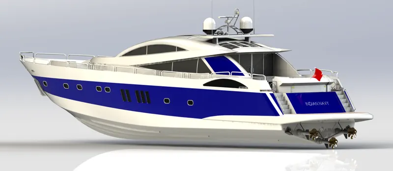
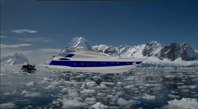
PACK AND GO: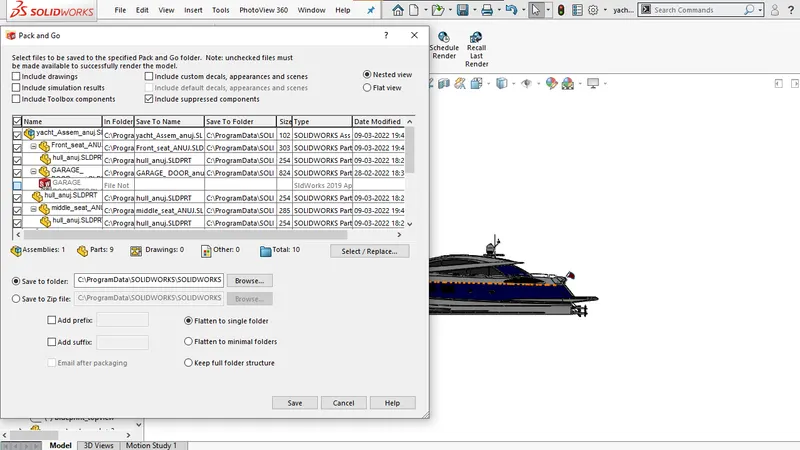
CONCLUSION: BY DOING THIS PROJECT WE LEARNED HOW TO OVERCOME WITH THE PROBLEMS WHICH COMES IN THE COMPLEX SURFACE DESIGNS.HOW TO USE 3D COMMANDS , HOW A SMALL COMMEN MISTAKE BECOME BIG WHEN WE IGNORE IT. AND WE HAVE TO DO CORRECT IT BY EDITING IN FEATURE TREE AND IF ALL THING BECOME CORRECT WE GET A SOLID AND KNIT BODY.