Week 8 - Challenge 3 - Coin Holder Design
DRAFT ANALYSIS REPORT
DRAFT ANGLE
A draft angle is a taper applied to the vertical walls of the injection molded component to assist with releasing the part from the mold
IMPORTANCE:
Draft angle is a required feature. A functional part for injection molding has to have drafts facing both cavity and core sides to reduce the risk of damage to the parts and ensure ejection. As the molten plastic flows into the closed die and fills the cavity, the material shrinks inside the mold upon cooling and as a result grips the core.
Without any taper, the part would come out scratched while increasing wear and tear on the mold and shortening the tool life. Even worse - if the part does not eject, it requires a production halt to manually peel it off.
Adding an adequate draft angle ensures that warpage upon ejection is prevented while maintaining a decent cosmetic finish.
ADVANTAGES
- Minimizes the warping to your geometry
- Increases the tool life of the mold
- Improves the surface finish on your plastic parts
- Cuts down cost by reducing the cooling time
BISECTING METHOD:
To create tooling direction we used bisecting method here. So first we took a point where we wanted our tooling direction to be and for that we created a point on the middle of the base of the class A surface of the Coin holder. So here there are four wall surfaces which are surrounding the base. So the idea is to create a mean line of these four surfaces which will be used as a tooling direction. This mean line actually represents the direction and the angle at which the tool will travel in the mould.
So to create this mean line we first took an axis system at the mid point. Then we took the intersection of class A surface at one direction which will divide the two surrounding surfaces and we got two lines at each sides. After that we created a centre line using bisecting line feature between those two lines and this will be used as a mean line for one direction. To create mean line for other direction we took intersection of the other surface and then did the same process as first.
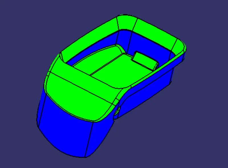
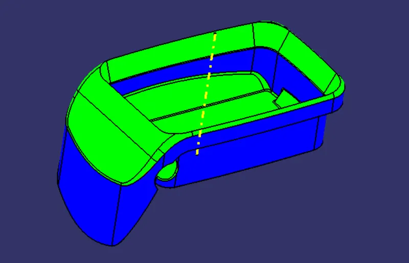
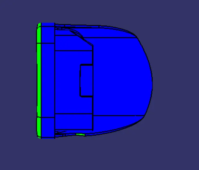
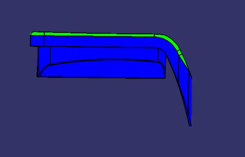
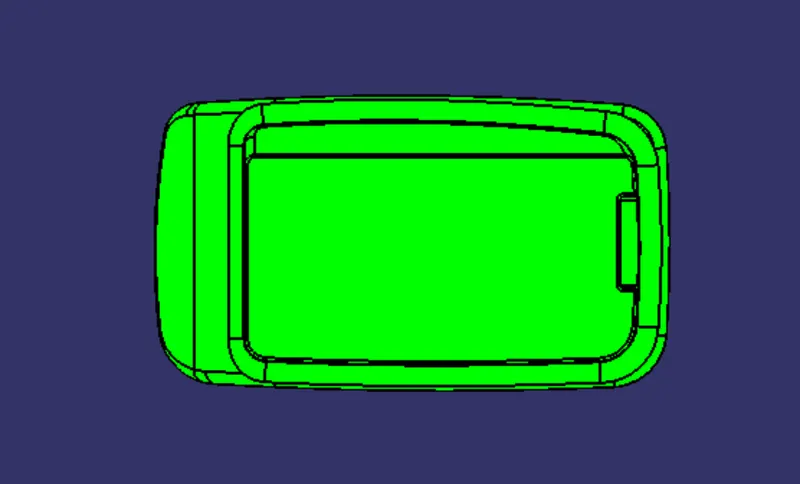
After getting both the mean lines for both directions we created main tooling line using bisecting line feature which is the centre line for both these mean lines. This tooling line is used as a tooling direction. At last we took a normal view to our tooling axis to check whether the line created is acceptable. After viewing we were able to see all the angular walls clearly so we can say that our tooling axis is correct. But here in coin holder we can see some low draft areas represented by the blue surfaces. So those are the unacceptable surfaces which need to be corrected by the class-A team. If not then those surfaces will create friction in the mould while ejection, which will result in scratches in surfaces.
DRAFT ANALYSIS:
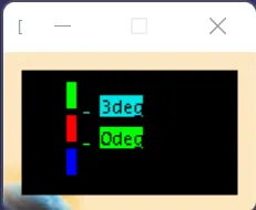
Draft analysis is a tool in the CAD modelling software using which we can analyse draft angle provided to any component. Draft is indicated through a colour scale variant. There are multiple colours on the scale which we can use to indicate the safe angles and unacceptable angles. Here in the analysis of a Coin Holder we have used green colour for safe angle and red clour for unacceptable angle. The provided draft angle for the analysis is 3 degrees.
For this we carried out the draft analysis. First we coincided the axis system to the tooling direction. Then we provided the surface as an input for analysis also mentioned the angle for analysis. Here the draft angle we took is 3 degrees. After analysis we got some green surfaces and some blue surfaces which meant that our component is not in acceptable angleswhich needs to be corrected by the class A team.
Draft analysis report for Class-A Surface
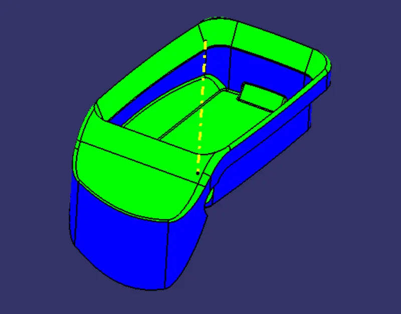
Draft analysis report for Solid model
Front View
Side View
Top View
Isometric View