Radar Mast & Final Assembly of Yacht
Aim - To model Radar mast and assembly of Yacht using Solidworks.
All views , fetaure tree and Reports are given below:
1)RADAR MAST
- Front view
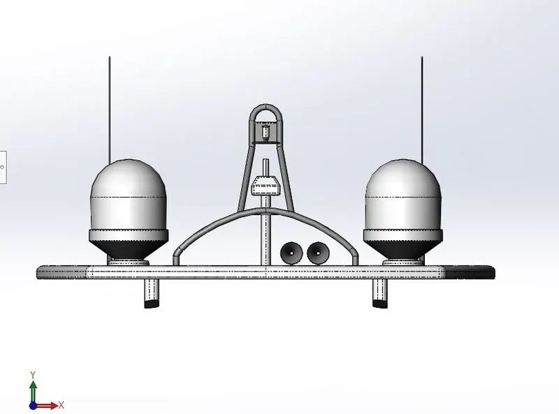
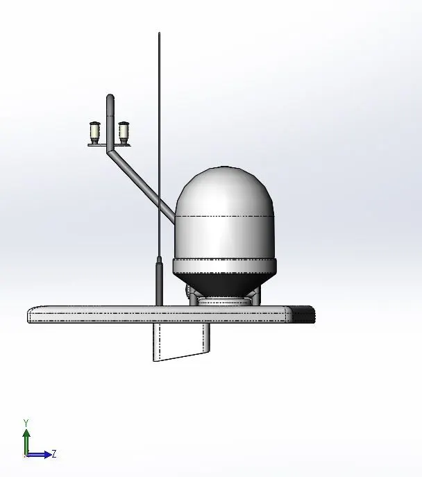
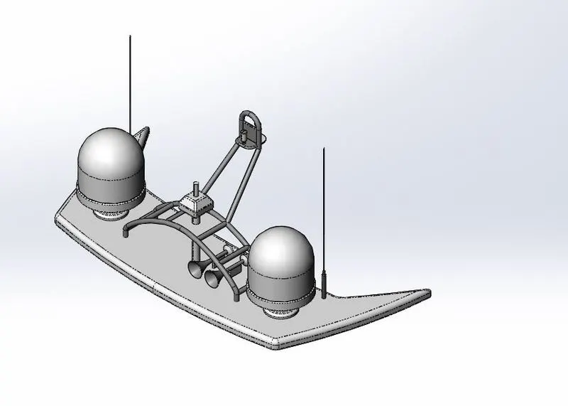
- Isometric View
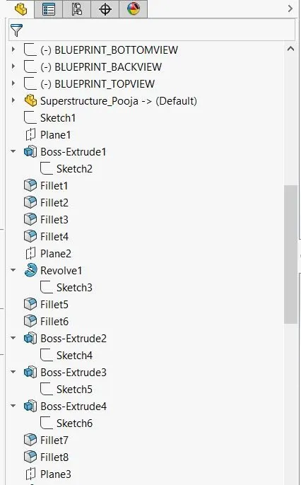
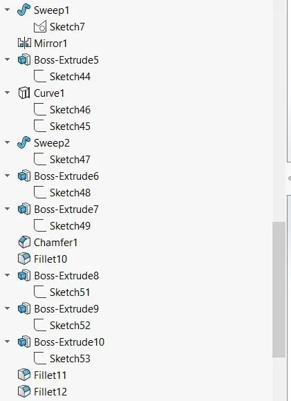
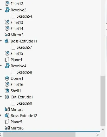
- Feature Tree
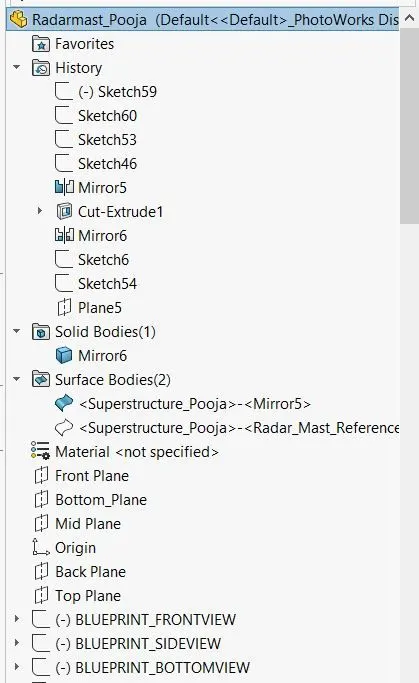
2)YACHT ASSEMBLY
All views and feature tree are as follows.
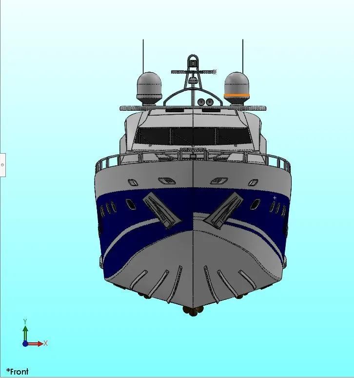
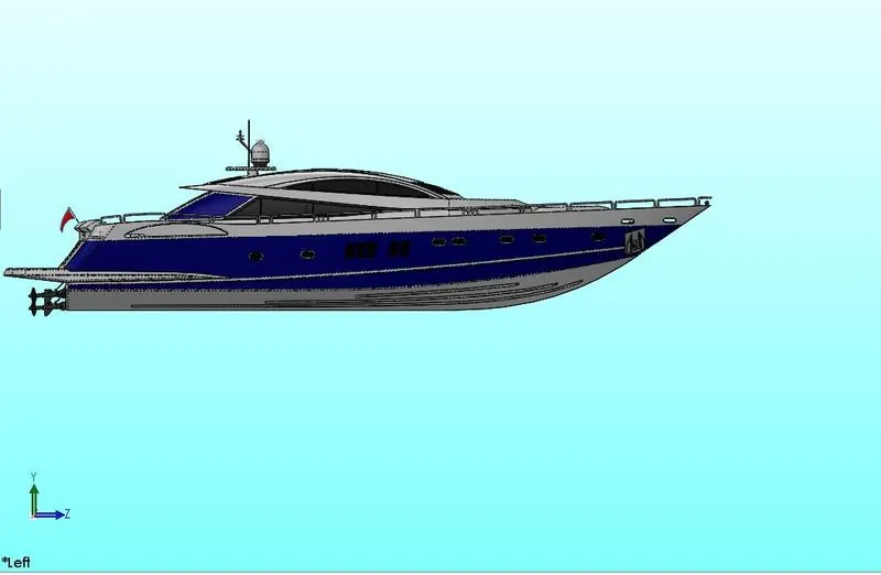
- Front_view
- Side view
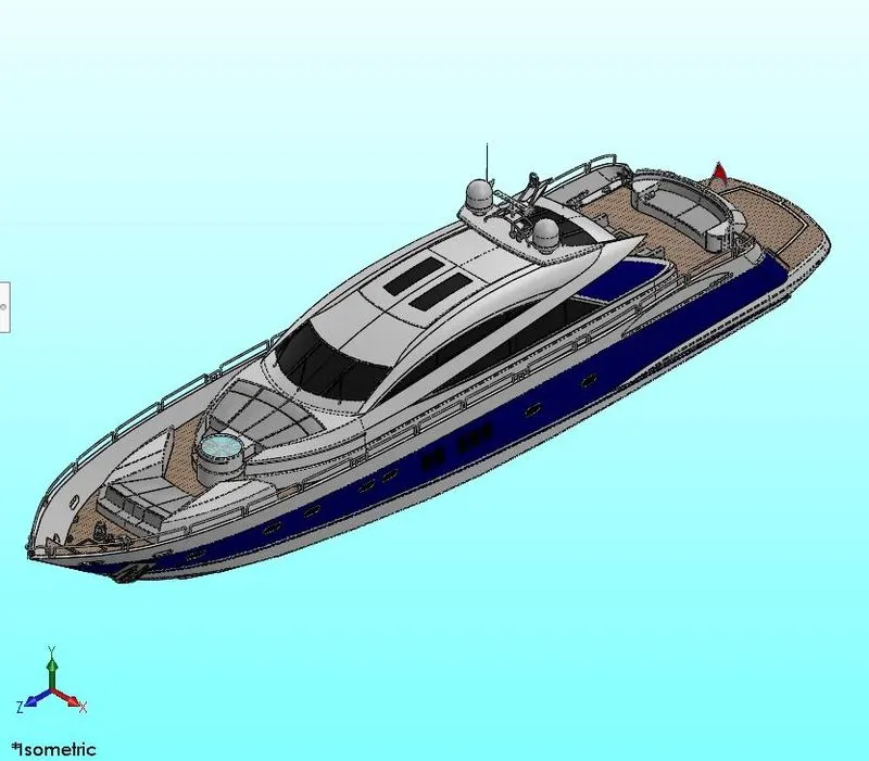
- Isometric view
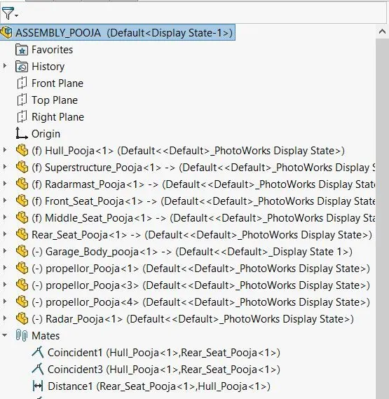
Feature Tree
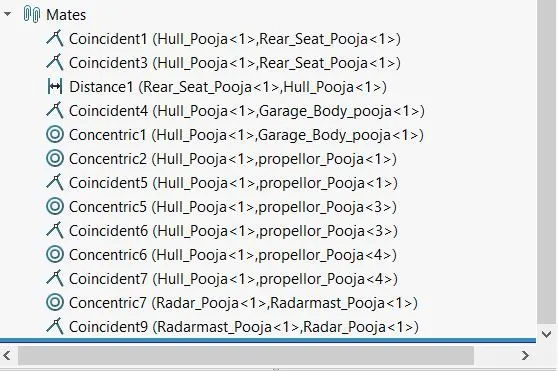
3)REPORT OF ASSEMBLY
MODELLING AND RENDERING OF AN PREDATOR YACHT
Objective:-
The objective of the project is to design and model all parts of Predator Yacht and assembly.
Introduction:-
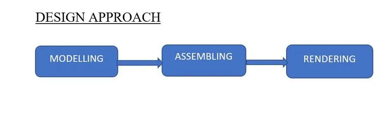
In this project we concentrate on solid modelling and Surface Modelling to model a Predator Yacht. Every single part was design in solidworks. Then all parts were assembled by adding mates to create Realistic image of the yacht.
SOLIDWORKS Visualize is a Realistic Rendering Tool that takes our assembly model to create quality images.
Photo-view 360 is a Solidworks add-in which also produces realistic models by changing scenes, decals, lightning effects and different appearances.
DESIGN SEQUENCE
In this project, we build a Predator yacht using solidworks to understand the 3D – Modelling methodology of Surface Modelling.
The following are the parts which we have modelled in Surface modelling using SOLIDWORKS,
- Blueprint set-up
- Modelling of Propellor, radar
- Modelling of Hull, Garage Door
- Modelling of Rear seats, Middle seats and Front seats
- Creation of Superstructure
- Assembly of Predator Yacht
TYES OF COMMANDS AND ITS EXPLANATIONS
Sketch – Every model usually begins with a sketch. Then we can apply dimensions and features.
3-D SKETCH
When sketching in 3D, we can snap to X, Y & Z direction and constraints are applied along those direction respectively.
SKETCH COMMANDS
Following are the sketch commands
- Line
- Circle
- Rectangle
- Spline
- Sketch Fillet
- Point
- Offset Entity
- Sketch Picture
- Convert Entity
FEATURES COMMANDS
- Extruded Boss/Base - This command allows us to take 2D sketch and apply thickness to it.
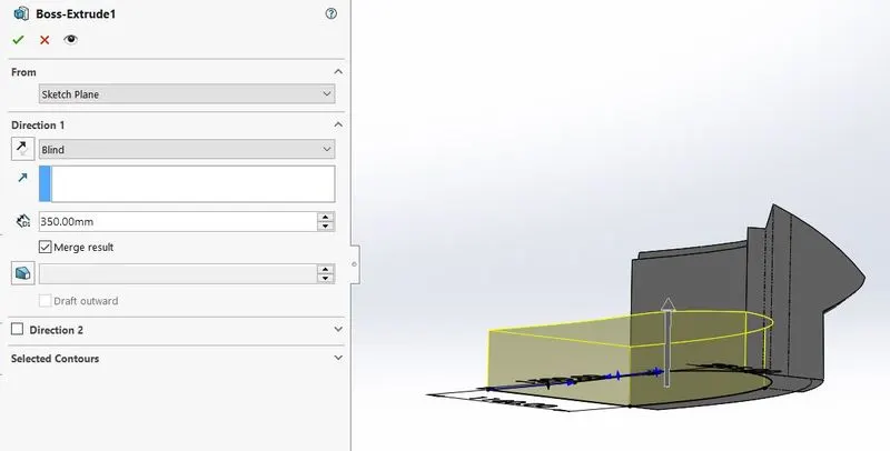
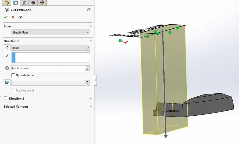
- Extruded cut- In this we can remove material by projecting sketch normal to plane.
- Split – Lines or splines are used to divide faces into two.
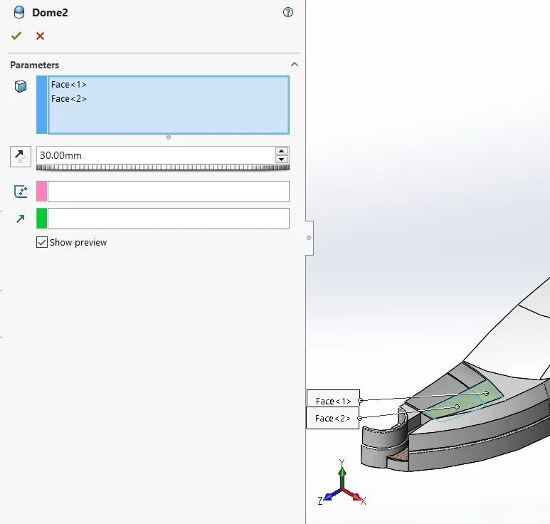
- Dome – It can add or calculate distance using radius of arc.
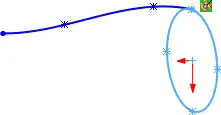
- Pierce – The pierce relationship is used in sweep.
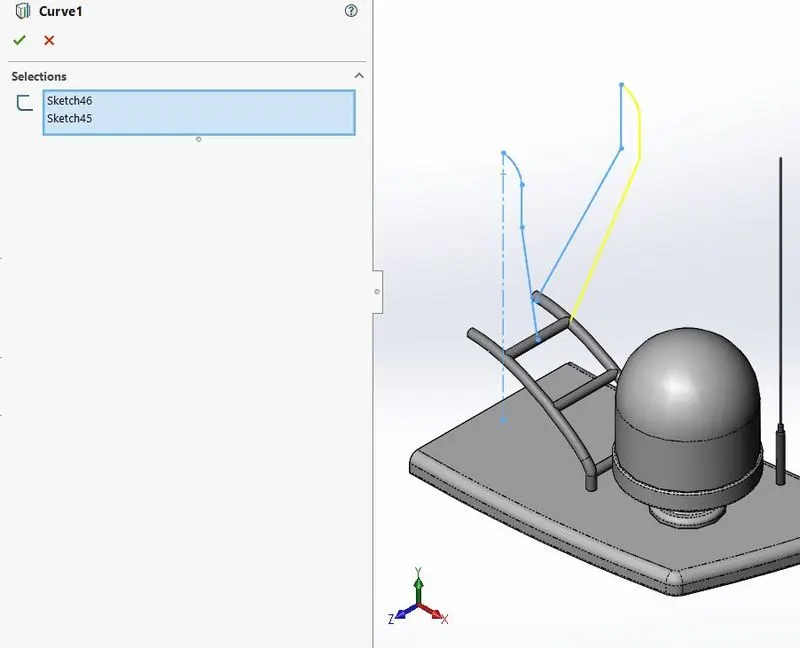
- Project Curve- Select Bidirectional to create a projection that extends on both sides of the sketch. The curve can be used as a path for a sweep.
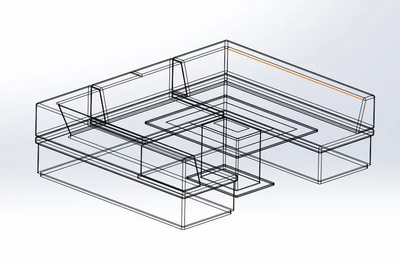
- Wire Frame - Wireframe ia s view mode in which all edges of part or assembly are displayed.
- SURFACE MODELLING
Surface modelling focuses more on the external body. The process requires us to convert between 3D modelling types. The surfaces are generally used to create models of complex shapes. We can covert surface models in solid models.
- SURFACE COMMANDS
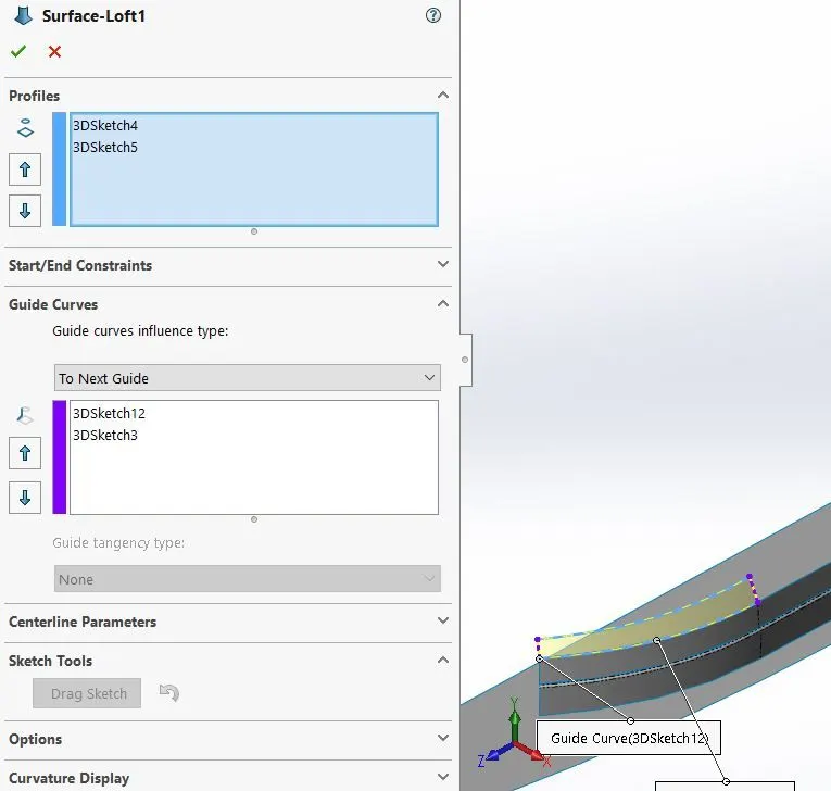
- Lofted Surface – It creates a lofted surface between two or more profiles or sketches. We have to specify start and end constraint and add guide curves to control the path shape.
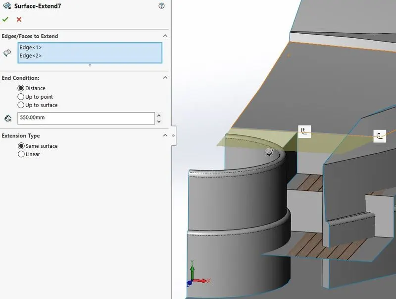
- Extend Surface – Extends one or more edges or faces on a surface, based on extension type.
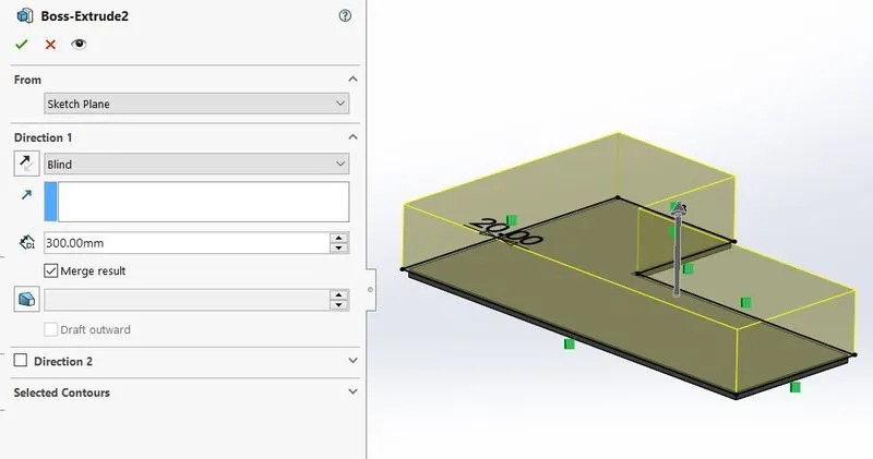
- Extruded Surface – Extrudes a sketch or selected sketch contours in one or two directions.
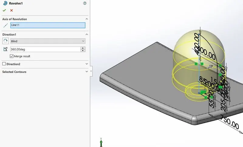
- Revolved Surfaces – Revolves a sketch or selected sketch contours around an axis to create a surface feature.
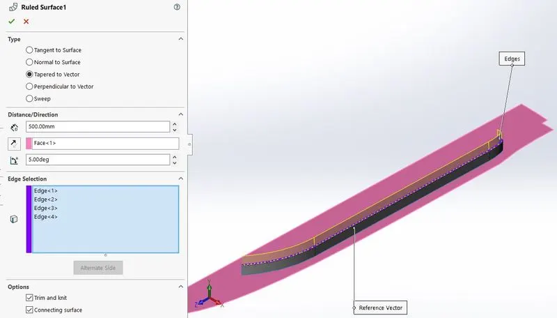
- Ruled Surface – Inserts ruled surfaces in a specified direction from edges. We can select four types such as Tangent to surface, Normal to surface, Perpendicular to vector and tapered to vector.
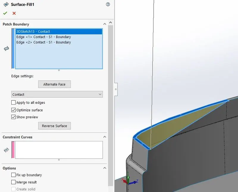
- Filled Surface – We can use this feature to construct a surface to fill gap in a model. This feature constructs a surface patch with any number of sides within a boundary of existing edges.
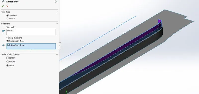
- Trim Surfaces – It trim the surface where it intersects with another surface, plane
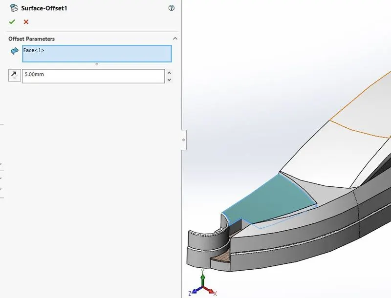
- Offset surface – This allows us to create an offset surface with gaps, by specifying required distance.
- Mirror Surface- Using this we can get exact replica of selected feature. We can mirror about Plane, faces. If the original feature or sketch is modified, the mirrored copy is updated to reflect the change.
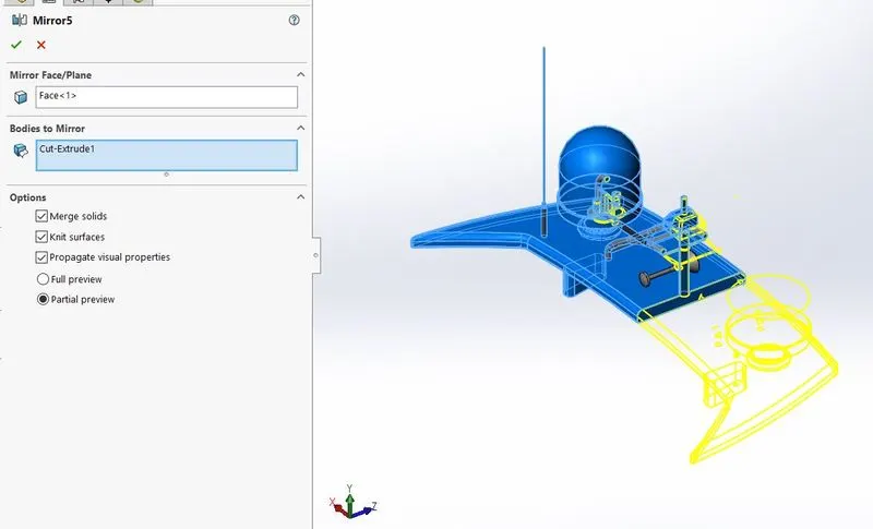
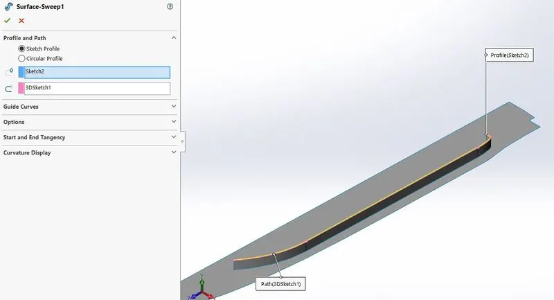
- Swept Surfaces – It sweeps a closed profile along an open or closed path to create surface feature.
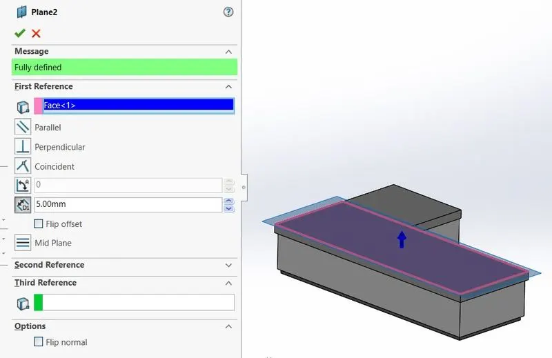
- Reference Plane – We can create planes in part, we can use planes to sketch, to create a section view of model.
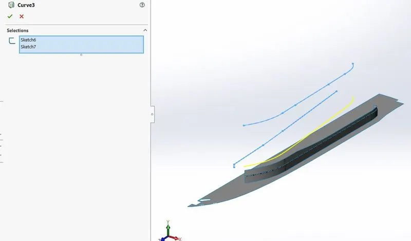
- Projected curve – A projected curve is typically used either in sweeps and loft as path or guide curves.
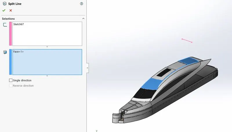
- Split Line – The Split tool projects an entity to surfaces. It can divide a selected face into multiple separate faces.
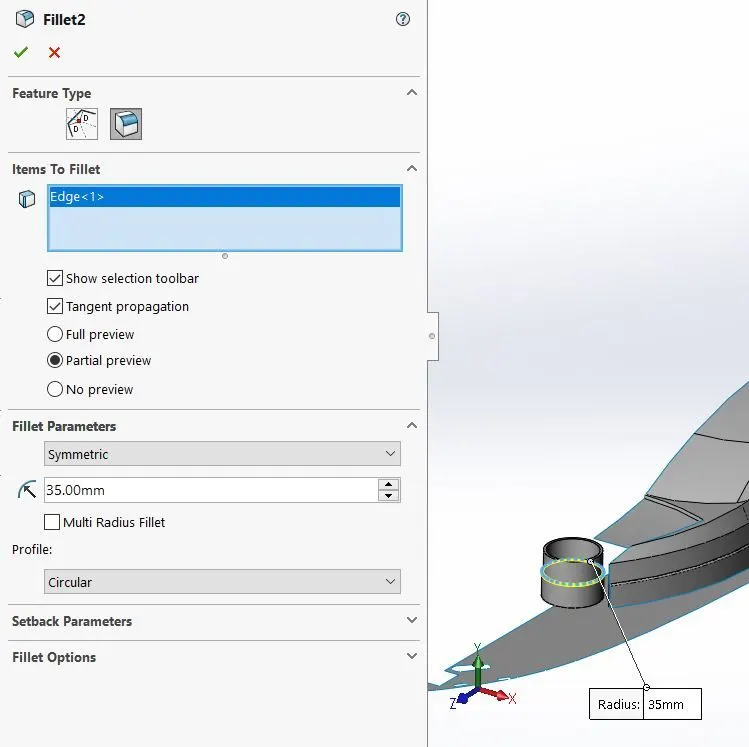
- Fillet – A fillet is a rounding of a corner or edge in a sketch or an edge on a surface.
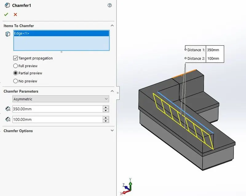
- Chamfer – The chamfer tool creates a beveled feature on selected edge, faces, or a vertex.
PARTS OF YACHT AND ITS FEATURES
1)BLUEPRINT
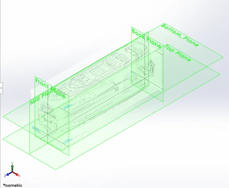
A blueprint is a reproduction of a technical drawing using contact print process on light sensitive sheets. At its most basic, a blueprint is a production of an image that already exist. These are easier to read and faster to make.
The below shown Blueprint was used to model the yacht. For setting up blueprint, the sketch pictures were used and placed with their respective distances.
2)HULL
A hull is a watertight body of a ship or boat. The hull may open at the top or it may be fully or partially covered with a deck. The line where the hull meets the water surface is called the waterline.
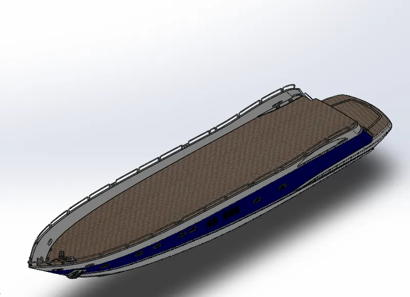
The first step for modelling yacht was creating a blueprint of it. Then curve has projected to get the shape of hull using splines. After that we created a lofted surface and trim unwanted surface. Another surface was created by using offset and filled the surface by using surface fill feature. Deck surface was created using boss extrude. All the windows and portholes were created using extrude cut and fillets were added. Then we created a rail at bottom and chamfer, it. By using slot option, the Rope hangers were extruded and Dome was applied and then Line pattern wea used. Then windows, staircase and hand support were created railings around the was generated with the help of blueprint. By using 3 D sketch we created Axle of propellor and surfer by applying Revolved boss/base. Then Anchors were created by sketching the first half and extruded using extrude boss and other half was mirrored. Finally, the Garage was created using extrude cut. And rest of the features we mirrored and saved the part.
Commands Used To Model
IN SKETCH
- Sketch pictures
- Line
- Circle
- Rectangle
- Arc
- Slot
- 3 -D ketch
IN SURFACES
- Extruded surface
- Revolved Surface
- Lofted Surface
- Surface TriM
- Surface Knit
IN FEATURE
- Extrude boss
- Extrude cut
- Reference plane
- Project curve
- Mirror
- Reference plane
- Fillet
- Chamfer
3)RADAR
Marine radars are short range radars used for locating other ships and land in the area. Ship radar are used as tracking ship devices. They are electronic navigation instruments that use a rotating antenna to sweep a narrow beam of microwaves around the water surface surrounding the ship to the horizon.
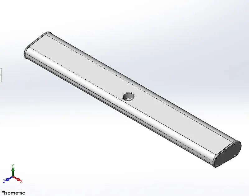
We draw required sketch of the body and radar was created using extruded Boss. By using sketch pattern holes were created and then applied extrude boss and cut feature. The Radar has a circular slot underneath which was created using extrude cut. The half was mirrored, Then Text over the Radar created using Text option. Then applied fillet wherever required and finally part was saved by adding appearance.
COMMANDS USED TO MODEL
In sketch
- Line
- Circle
- Text
- Point
In Feature
- Extruded boss/base
- Extruded cut
- Sketch pattern
- Fillet
- Mirror
- Split line
4)PROPELLER
There can be one, two or three propellors. It is the most important part of the ship without which a ship can’t move, so the main function of propeller is to propel the ship in the forward direction by producing thrust on water. It is based on Newton’s third law of motion and Bernoulli’s theorem.
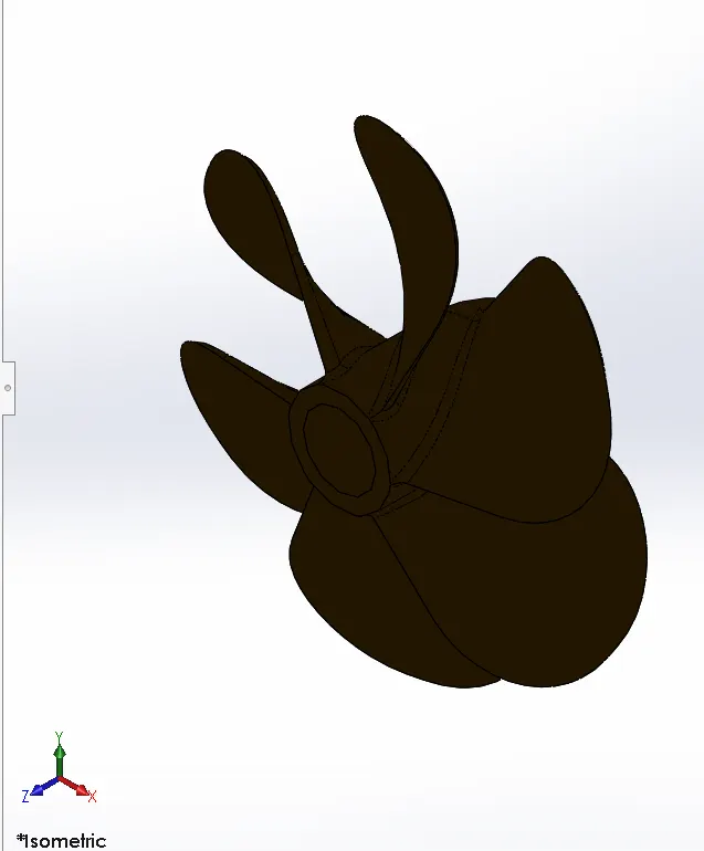
The centre portion of the Propellor was sketched and revolved using Revolved boss. Then the blades were created using Reference Plane, Lofted boss and fillet. Then the remaining five blades were created by using circular pattern. Then the centre circular portion was removed by extrude cut and finally part was saved by adding appearance.
COMMANDS USED TO MODEL
IN SKETCH
- Spline
- Circle
- Line
IN FEATURE
- Revolved Boss/Base
- Lofted Boss/ Base
- Extruded Cut
- Reference Plane
- Circular Pattern
- Fillet
5)GARAGE DOOR
Garage door is a large door on a garage that opens either manually or byb an electric motor. Garage doors are large enough to accommodate automobiles and other vehicles. The operating mechanism is spring -loaded or counterbalanced to offset the weight of the door and reduce human effort required to operate the door.
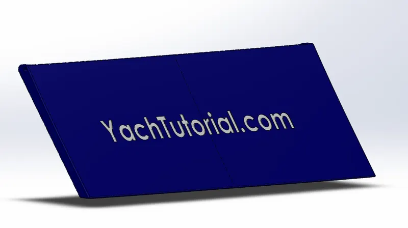
In this we split the solid body while creating Hull to model the Garage Door. Then we applied extrude cut and chamfered the face for the Door creation. Then solid body of Garage door was created by shell feature and filets are applied. Then created Door holders on both sides using extrude cut. Then we apply mirror to get the whole body. After that Text over the Garage door was created using Text option in sketch feature, finally by adding appearance part was saved.
COMMANDS USED TO MODEL
IN SKETCH
- Line
- Spline
- Circle
- Text
IN FEATURE
- Extrude cut
- Reference plane
- Shell
- Fillet
- Mirror
6)FRONT SEAT
The front seat in our model was placed before the superstructure and also it has sun pads rest on it. Front seats are the two connected seats that are built back-to-back from one and other. They have a built-in storage unit underneath them.
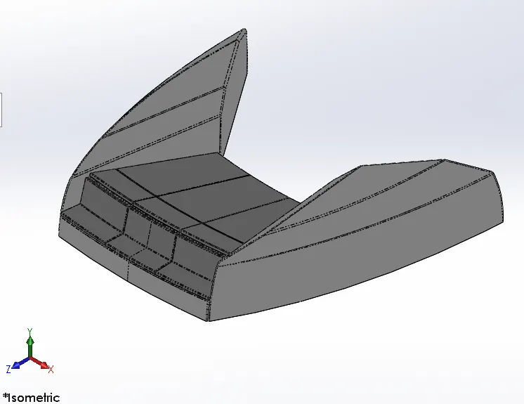
The front seat of the yacht was also created with the help of Blueprint. The first half was modelled and half was mirrored. The front seat was placed before the superstructure. The body of the Front seat was modelled using swept surface, extruded surfaces, filled surface, lofted surface and unwanted part was removed using trim surface. Then four Rest Beds were created using Extruded boss and Dome was created over the face of the beds separately. Then the required fillets and chamfers were applied with extruded thin surfaces. Finally, appearance was added and part was saved.
COMMANDS USED TO MODEL
IN SKETCH
- Line
- Spline
- Circle
- Arcs
IN SURFACES
- Extruded surface
- Lofted Surface
- Surface Trim
- Filled Surface
- Surface Knit
- Swept Surface
- Revolved Surface
IN FEATURE
- Extrude cut
- Revolved Boss/Base
- Chamfer
- Fillet
- Mirror
- Dome
7)MIDDLE SEAT
The middle seat in our model was placed just behind the superstructure. It is provided with a luxury table to dine out.
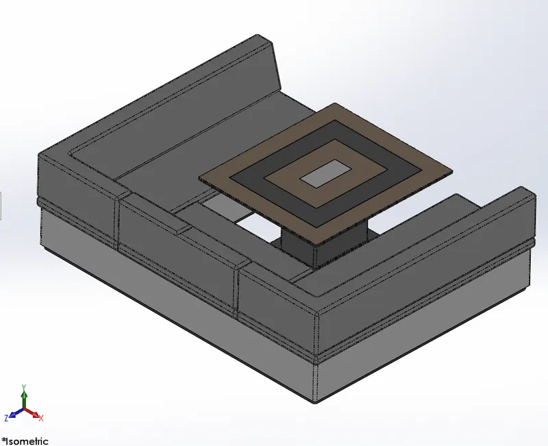
The middle seat was created using Extruded boss and applied chamfers and fillets. All the surfaces created must be knitted together by using surface knit feature. The dining table was created using Reference plane, Extruded boss, offset chamfers and then applied mirror. Then the second half of the seat was mirrored symmetrically added appearance and saved the par
COMMANDS USED TO MODEL
IN SKETCH
- Sketch Picture
- Line
- Rectangle
IN FEATURE
- Extrude Boss/base
- Fillet
- Chamfer
- Mirror
- Reference plane
8)REAR SEAT
The rear seat was placed at the end of the deck surface. The rear seat consists of locker racks and doors. The flag was also placed behind the rear seat since it’s the end part of our Yacht.
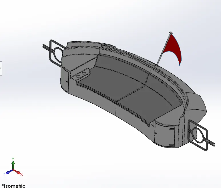
The main body of the Rear seat was modelled using swept surface, offset surface and then applied trim surface.by using reference plane the Seats were created by using Lofted surface, trim surface and Extended surface. The Flag post was created using Revolved boss and Flag was created using 3D sketch and the 3D sketches were lofted to form Flag. Then by using extrude boss Tail Lamps were created and applied Fillets and Mirror. The Steel Gates for Stairs was designed by using reference plane and swept surface. To remove gaps all surfaces must be knitted using knit surface. Then applied required chamfers and fillets and mirror the second half using mirror tool. To get part more realistic we added appearance and part was saved.
COMMANDS USED TO MODEL
IN SKETCH
- Sketch Picture
- Line
- Spline
- Circle
- Arcs
- Rectangle
IN SURFACES
- Swept surface
- Extruded surface
- Off-set Surface
- Filled Surface
- Surface Knit
- Ruled Surface
- Lofted Surface
IN FEATURE
- Reference plane
- Extrude Boss/Base
- Revolved Boss/Base
- Fillet
- Mirror
9)SUPERSTRUCTURE
Often it is called as Bridge or Deckhouse. A superstructure is an upward extension of an existing structure above a baseline called ground level. 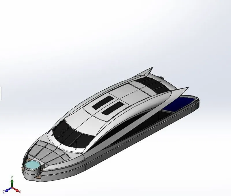
The deck surface from the hull was imported and then the superstructure was modelled over it. The side surface of the superstructure was created by using Extruded surface, lofted, filled and trim surface and then knitted the surface. The front edge of the superstructure was provided with a water feature which was created by using extruded boss, extruded cut and filled with a water appearance windshield was created by extruded cut and the wipers were created using 3D sketch and reference plane with the help of swept boss/base. The portholes for the superstructure were created by using extruded surface trim and extended surface. Ruled Surface was used to fill the left-out edges.
The back Doors of the superstructure was created using extruded cut, filets and reference plane. Then all the surfaces generated were knitted to form a solid body. The superstructure consists of two surface bodies and five solid bodies. One of the surfaces of superstructure was used to place the Radar Mast so it was named as Radar Mast Reference.
Then rest half was mirrored by applying proper fillets and appearance and part was saved.
COMMANDS USED TO MODEL
IN SKETCH
- Sketch Picture
- 3D sketch
- Line
- Spline
- Circle
- Arcs
- Rectangle
- Centre point Arc
IN SURFACES
- Extruded surface
- Swept surface
- Ruled Surface
- Surface Knit
- Surface Trim
- Extend Surface
- Filled Surface
- Lofted Surface
- Revolved Surface
- Fillet
- Chamfer
IN FEATURE
- Project curve
- Reference curve
- Convert Entities
- Split
- Split Line
10) RADARMAST
A mast is a vertical ship structure mounted on top of bridge and forward of forecastle towards the ship’s bow. It accounts for the support platform for the ships derrick and hold necessary equipment such as radars, navigation light and ships horn in case of foremast.
The first half of the Radar was modelled with the help of blueprint and then other half was mirrored by using mirror tool. The body of Radar was created using Extruded boss and Revolved boss. Extruded boss was also used to create antenna for Radar. The lamp stand along with the connecting rod were created using swept boss and mirror tool. Then we created a projected curve to create lamp and curve was swept using swept boss/base. The horns were created using Revolved boss, Dome and shell. Fillets and chamfers were applied wherever required. Finally, appearance was added to look more realistic part was saved.
Commands Used To Model
IN SKETCH
- Sketch Picture
- Line
- Spline
- Arcs
- Rectangle
IN FEATURE
- Extruded Boss/Base
- Lofted boss
- Revolved
- Swept
- Reference plane
- Projected curve
- Fillet
- Mirror
- Dome
- Shell
ASSEMBLY
In this, whole existing parts of model are taken and give mates like coincident, concentric, etc.
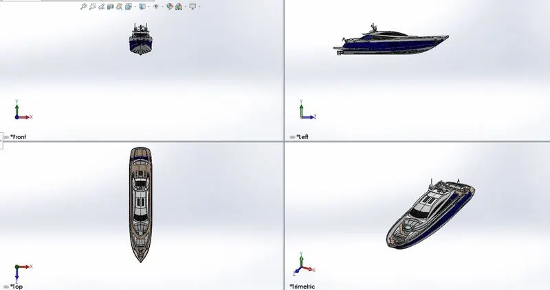
Assembly Procedure
- We have imported all the parts manually by using insert component option.
- Advanced mate was also used wherever required.
- Then fix the hull part by applying coincident mate.
- Then for each part we applied necessary mates required by the blueprint using coincident mates, concentric mates, etc.
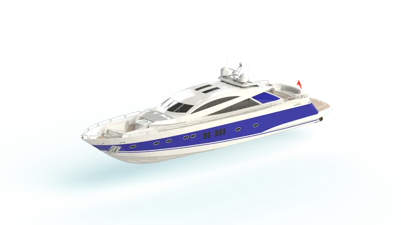
RENDERING
Rendering of the Solid works model is done using Photoview 360 and solidworks visualize.
- Photoview 360 is a visualization and rendering solutions, providing interactive environment for viewing designs as well as for creating photo – realistic renderings. It can be used to showcase our designs.
- Solidworks Visualize provides0 quick and easy, professional photo quality images. We can say Solidworks Visualize is Camera for our CAD data.Solidworks visualization provides the right combination of quality, speed, and ease of use and is the best render.
Conclusion
Thus the project design , assembly and Photo Realistic Rendering of American Predator Yatch modelled successfully.