Radar Mast & Final Assembly of Yacht
|
SKILL LYNE |
|
SUNSEEKER PREDATOR YACHT |
|
|
|
Swaroop S Thakur |
|
11/21/2021 |
|
|
OBJECTIVE
The main objective is to create suraface modelling of different parts YACHT. The software is mainly used to model 3D parts using 2D sketch. It also tells about rendering of the model using Solidworks Visualize & Photo view360 to make the YACHTmore and realistic.
MODELLING & ASSEMBLING FEATURES
The various type modelling features used for modelling the YACHT are discussed below.
SKETCH
Sketch is a two dimensional 2D into a solid modelling only when the 2D sketch completely closed .It also allows to extrude the surface in both direction and also offset it to require distance.
EXTRUDE
Using the solid works Surface Extrude feature, we can extrude the boundary edges of a face of a solid body or edges of a surface body in a customized direction.
REVOLVE
The revolve feature is used to revolve a 2D sketch along an axis or centreline and makes it a 3D model. A 2D sketch is
drawn and revolved by selecting a line as a reference for axis of rotation and defining the angle of rotation.
LOFT
The loft feature allows you to generate complex geometry .It does this by interpolating surface between various cross section of the model. These cross sections can be sketches, faces or edges . In the loft interface the cross sections are considered as Loft profiles.
SWEEP
A sweep tool is used to sweep a closed 2D sketch along an open or closed path. This tool is generally used for making tubes and bars. A closed loop and a path sweep are required.
CHAMFER
A chamfer is used to remove a sharp edge by creating a sloped edges, vertex or face. Distance and angle of the chamfer are defined.
FILLET
A fillet is a tool used to round an edge, vertex or face on both inside and outside of 2D or 3D model. The fillet type, Location and radius of the fillet are defined.
EXTRUDE CUT
It is used to remove materials from a solid model in desired patterns and also it can be extruded with n=both directions.
COMBINE
Combine feature is used to combine two or more bodies when intersecting to each other and make it in a single body.
MIRROR
Mirror tool in solidworks is used to copy a 2D or 3D object about a reference line or plane. We can have either only the mirrored object or both the original and mirrored objects.
MATES
Mate is operation is the basic tool for assembling the parts, There are various mate operation such as coincident, parallel, perpendicular, tangent, concentric, lock, etc. We can two faces by defining distance or angle between them.
PROJECTED CURVES
A projected curve is a 3D curve that represents the intersection of two extruded surface of two sketches on intersecting planes.
LINEAR & CIRCULAR PATTERN
The Linear Pattern Command is used to drive features, faces or bodies in a linear directions. The circular pattern command is an excellent tool used to replicate features, faces or bodies in a rotational manner about an axis.
SURFACE LOFT
Loft Surface are surfaces generated by multiple 3D Curves or existing edges creating a smooth tangency between the selected curves.
EXTRUDE SURFACE
Using the SOILDWORKS Surface Extrude feature, we can extrude the boundary edges of face of a solid body or edges of a surface body in a customizes direction.
SURFACE TRIM
To trim a surface Create two or more surface that intersect at one or more points, or create a surface that intersects with a plane or has a sketch on its face.
SURFACE SWEEP
Sweep Surface are surface that are generated from a section curve positioned along a path. Parallel Sweep is defined as a section curve moving along a guide path while maintaining the section curve to be parallel to the guide path.
SURFACE KNIT
Use the Knit Surface tool to combine two or more faces and surfaces into one Create a solid body when the knit surface form a closed volume or leave as a surface body select merge entities to merge faces with the same underlying geometry
Ruled SURFCAE
The Ruled Surface command create surface that extend out in specified direction from selected edges Examples of how you can use ruled surfaces add tangent extension to complex surface Create drafted sidewall Replace non-drafted surfaces on imported models with drafted surface
DOME
The Softwere calculates the distance using the radius of the arc as a basis for the dome. It create a dome that is tangent to the adjacent cylindrical or conical face.
SURFCAE OFFSET
The Surface offset tool is useful way of creating a series of deposit or erosion contact surafce from a reference mesh.
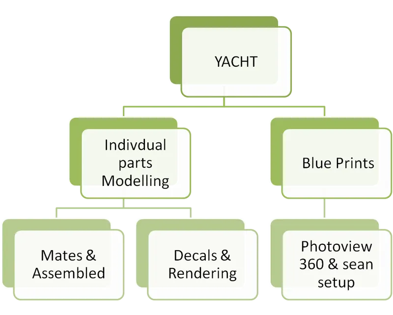
Design Flow chart of YACHT
MODELLING OF SUNSEEKAR YACHT PARTS
PROPELLER
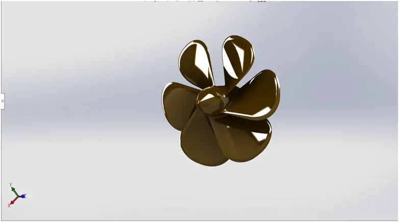
A Propeller or Prop is the final final piece of the engine and its drive train. It is the part of the boat that transfers the engine horsepower to the water. The transfer is termed as thrust. Thrust is created as the propeller pulls water into the front of it.
COMMAND USED IN PROPELLER
- Sketch
- Revolve
- Loft
- Cut Extrude
- Fillet
- Circular Pattern
RENDRED IMAGE
RADAR
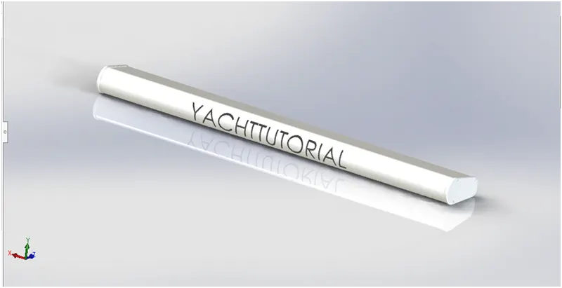
Radar is an acronym for Radio Detection and Ranging. It is a device capable of detecting objects. At far off distance, measuring the distance or range of the object by using electromagnetic waves.
COMMAND USED IN RADAR
- Sketch
- Boss Extrude
- Fillet
- Cut Extrude
- Sketch Pattern
- Mirror
- Split Line
RENDRED IMAGE
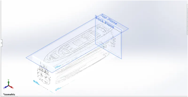
BLUE PRINTS
For Reference.
HULL PART
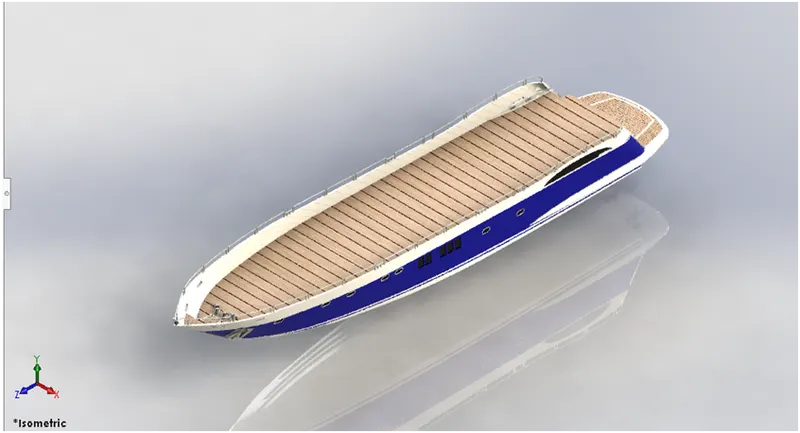
A Hull is the watertight body of a ship, boat, or flying boat.The hull may open at the top or it may be fully or partially covered with a deck. Atop the deck may be a deckhouse and other superstructures, such as a funnel, derrick, or mast.
COMMAND USED IN HULL PART
- Sketch
- Projected Curve
- Surface loft
- Surface Trim
- Surface Knit
- Shell
- Boss Extrude
- Chamfer
- Fillet
- Cut Extrude
- New Plane
- Sweep
- Extrude Thin
- Revolve
- Linear Pattern
- Mirror
- 3D sketch
- Split
- Deckn Surface
RENDRED IMAGE
GARAGE DOOR
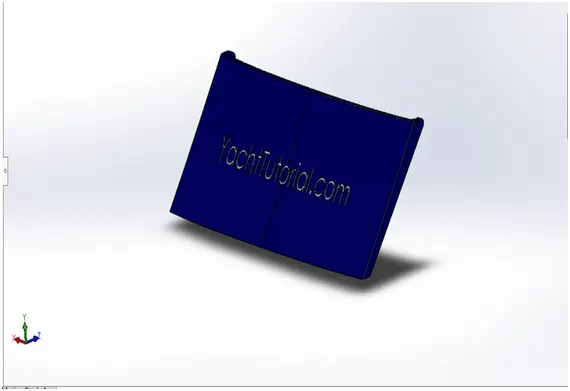
Superyachts often feature stern garages, which house the tender and the other water toys. Superyacht tenders includes influenced boats, custom made luxury tenders and support vessels that follow the yacht.
COMMAND USED IN GARAGE DOOR
- Sketch
- Cut-Extrude
- Shell
- Fillet
- Mirror
RENDRED IMAGE
FRONT SEAT
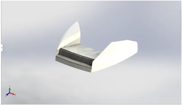
The front of a boat is called the bow, while the rear of a boat is called the stern. When looking towards the bow, the left hand side of the boat is the port side. and starboard is the port side.
COMMAND USED IN FRONT SEAT
- Surface Sweep
- Surface Extrude
- Surface Trim
- Surface Loft
- Surface Knit
- Chamfer
- Revolve
- Fillet
- Mirror
- Cut-Extrude
- Dome
RENDRED IMAGE
MIDDLE SEAT
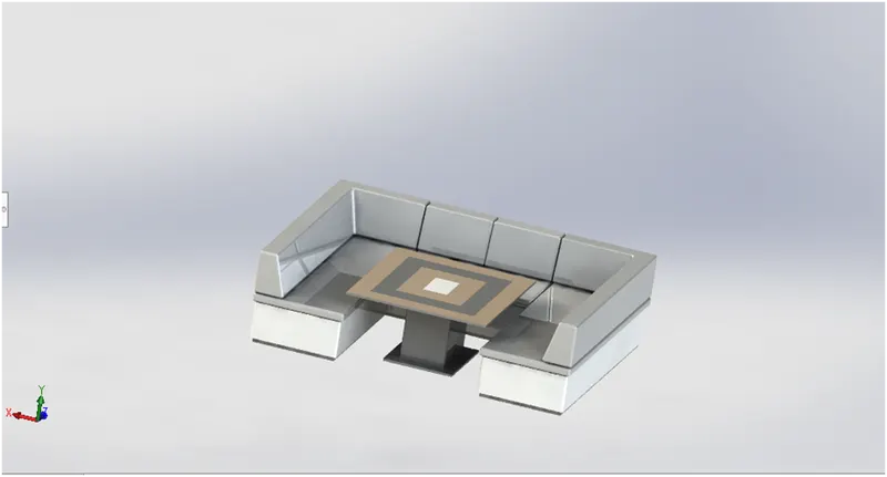
The front of a boat is called the bow, while the rear of a boat is called the stern. When looking towards the bow, the left hand side of the boat is the port side. and starboard is the port side.
COMMAND USED IN MIDDLE SEAT
- Boss Extrude
- Chamfer
- Mirror
- Fillet
RENDRED IMAGE
REAR SEAT
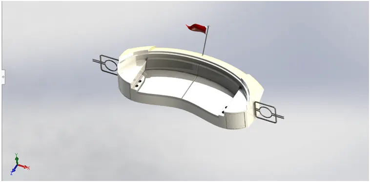
The front of a boat is called the bow, while the rear of a boat is called the stern. When looking towards the bow, the left hand side of the boat is the port side. and starboard is the port side.
COMMAND USED IN REAR SEAT
- Surface Sweep
- Surface Trim
- Surface Knit
- Rulled Surface
- Boss Extrude
- Chamfer
- Fillet
- Surface Offset
- Sweep
- Revolved
- Mirror
- Surface Loft
RENDRED IMAGE
SUPERSTRUCTURE
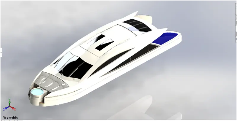
The definition of a building or part of a built above the foundation .An example of a superstructure is the lobby and floors in a high rise building. The part of a ship above the main deck.
COMMAND USED IN REAR SEAT
- Surface Extrude
- Surface Sweep
- Projected Curve
- Surface Loft
- Surface Fill
- Surface Knit
- Surface Trim
- Surface Loft
- 3D Sketch
- Ruled Surface
- Deleted Face
- Fillet
- Surface extend
- Cut-Extrude
- Thicken
- Dome
- Extrude Thin
- Split line
- Mirror
- Radar interface surface
RENDRED IMAGE
RADAR MAST
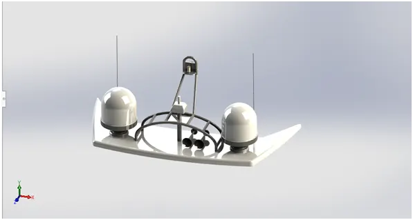
They are electronic navigation instruments that use a rotating antenna to sweep a narrow beam of microwaves around the water surface surrounding the ship to the horizon, detecting targets by microwaves reflected from them, generating a picture of the ships surroundings on a display screen.
COMMAND USED IN REAR SEAT
- Boss Extrude
- Fillet
- Revolve
- Sweep
- Mirror
- Project Curve
- Chamfer
- Dome
- Shell
RENDRED IMAGE
ASSEMBLY OF THE YACHT
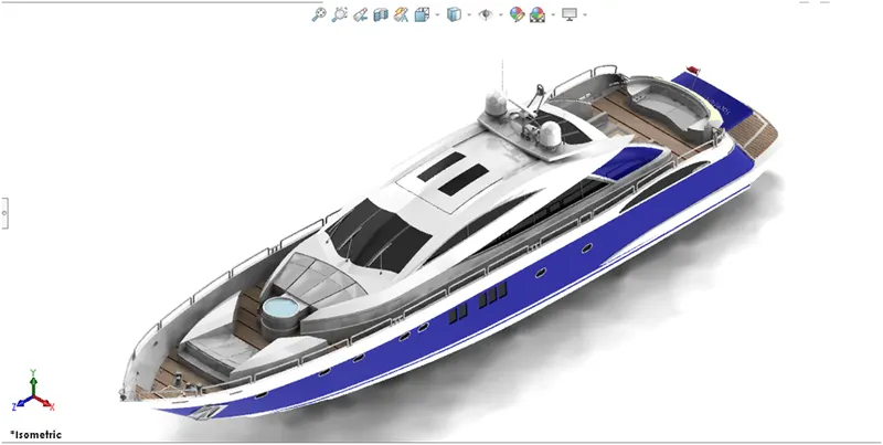
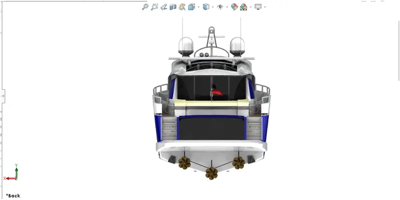
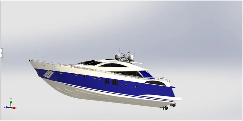
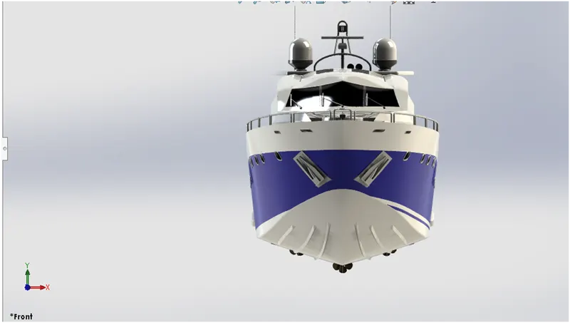
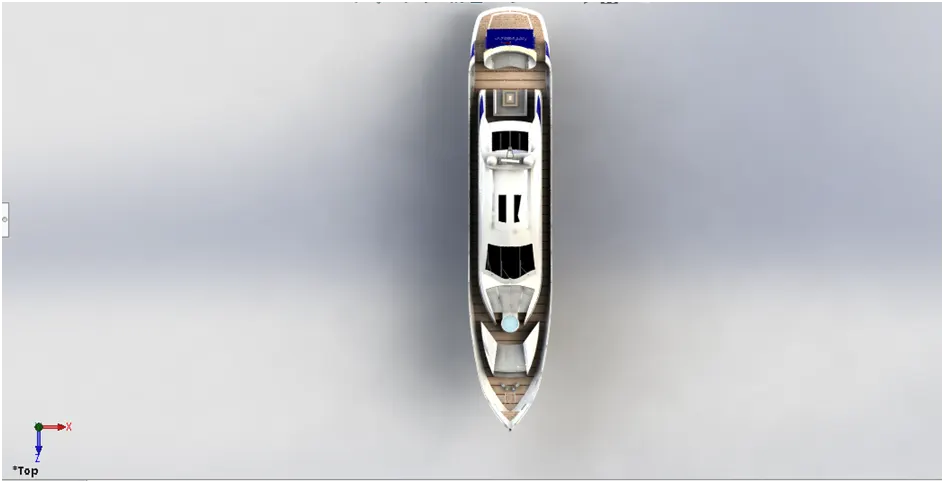
All the parts modelled were imported to assemble them. In assembly mate feature was used to locate and relate the parts with one another. Desk was inserted initially and fixed. The other components were inserted and related to the Desk.
RENDERING OF THE YACHT
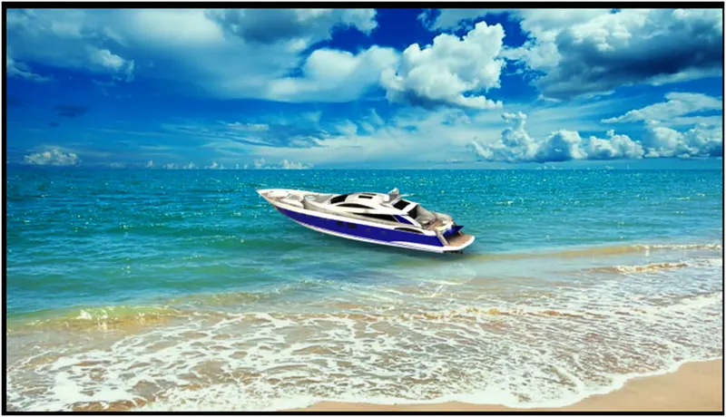
Rendering is a process creating realistic images of the photorealistic model with the environment. Renderings has done in two ways in soildworks . Photoview360 and Visulaize.
In this model i have done with Photoview 360
Photoview360 is a visualization and rendering solution includes with soildworks. Providing a highly interactive environment for viewing designs as well as for creating photorealistic rendering it can be used to showcase our designs as well.
CONCLUSION
The parts of the YACHTr are modelled
The realistic images was rendered with Photoview360
The parts are inserted into the assembly environment and the YACHT is assembled.