Photo Realistic Rendering
|
SKILL LYNE |
|
AMERICAN CHOPPER BIKE MODELLING AND RENDERING |
|
|
|
Swaroop S Thakur |
| 02/10/2021 |
|
|
OBJECTIVE
The main objective is to create solid modelling of different parts in American chopper. The software is mainly used to model 3D parts using 2D sketch. It also tells about rendering of the model using Solidworks Visualize & Photo view360 to make the chopper more and realistic.
INTRODUCTION
American Copper is an American reality television series that airs on Discovery Channel Produced by Pilgrim Films & Television.The series centers on Paul Teutul Sr. and his son Paul Teutul jr. who manufacture chopper style bike.
MODELLING & ASSEMBLING FEATURES
The various type modelling features used for modelling the American Chopper bike are discussed below.
SKETCH
Sketch is a two dimensional 2D into a solid modelling only when the 2D sketch completely closed .It also allows to extrude the surface in both direction and also offset it to require distance.
EXTRUDE
Using the solid works Surface Extrude feature, we can extrude the boundary edges of a face of a solid body or edges of a surface body in a customized direction.
REVOLVE
The revolve feature is used to revolve a 2D sketch along an axis or centreline and makes it a 3D model. A 2D sketch is drawn and revolved by selecting a line as a reference for axis of rotation and defining the angle of rotation.
LOFT
The loft feature allows you to generate complex geometry .It does this by interpolating surface between various cross section of the model. These cross sections can be sketches, faces or edges . In the loft interface the cross sections are considered as Loft profiles.
SWEEP
A sweep tool is used to sweep a closed 2D sketch along an open or closed path. This tool is generally used for making tubes and bars. A closed loop and a path sweep are required.
CHAMFER
A chamfer is used to remove a sharp edge by creating a sloped edges, vertex or face. Distance and angle of the chamfer are defined.
FILLET
A fillet is a tool used to round an edge, vertex or face on both inside and outside of 2D or 3D model. The fillet type, Location and radius of the fillet are defined.
EXTRUDE CUT
It is used to remove materials from a solid model in desired patterns and also it can be extruded with n=both directions.
COMBINE
Combine feature is used to combine two or more bodies when intersecting to each other and make it in a single body.
MIRROR
Mirror tool in solidworks is used to copy a 2D or 3D object about a reference line or plane. We can have either only the mirrored object or both the original and mirrored objects.
MATES
Mate is operation is the basic tool for assembling the parts, There are various mate operation such as coincident, parallel, perpendicular, tangent, concentric, lock, etc. We can two faces by defining distance or angle between them.
PROJECTED CURVES
A projected curve is a 3D curve that represents the intersection of two extruded surface of two sketches on intersecting planes.
LINEAR & CIRCULAR PATTERN
The Linear Pattern Command is used to drive features, faces or bodies in a linear directions. The circular pattern command is an excellent tool used to replicate features, faces or bodies in a rotational manner about an axis.
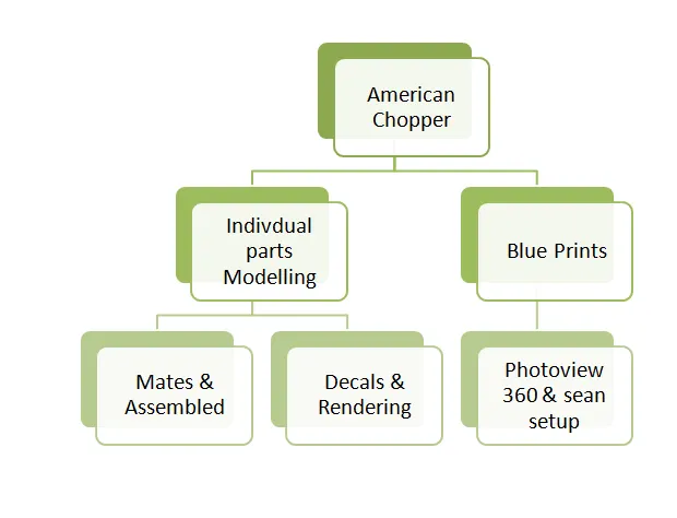
Design Flow chart of American chopper
MODELLING OF AMERICAN COPPER BIKE PARTS
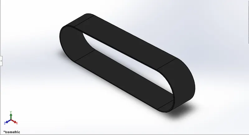
TRANSMISSION BELT
Belts are mechanical elements used for power transmission without phase shift. They are loops of flexible materials used to mechanically connect several rotating shafts, most often parallel. Belts can be used as a transmission element, to efficiently transmit power or movement.
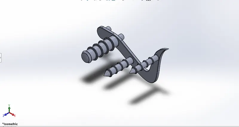
KICKSTAND
A kickstand is a device on motorcycle that allows the bike to be kept upright without leaning against another object or the aid of a person. A kickstand is usually a piece of metal that flips down from the frame and makes contact with the ground.
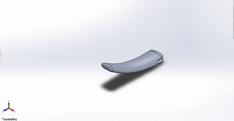
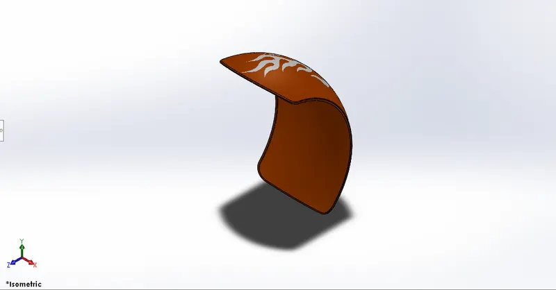
FRONT FENDER
A Fender is the part of a car, truck or motorcycle that surrounds the wheel well. The primary function of a Fender is to prevent dirt and debris from being thrown into the air by the tire.
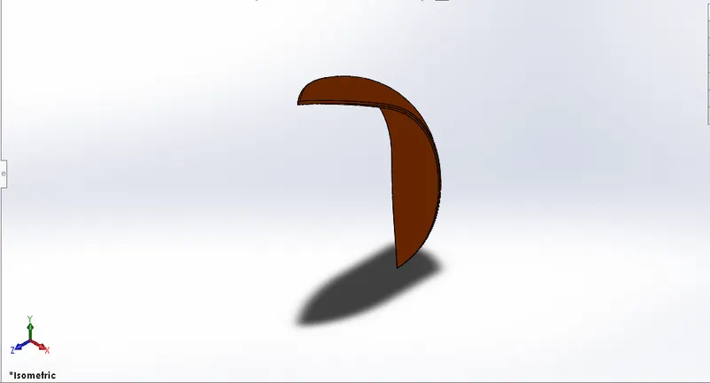
REAR FENDER
A Fender is the part of a car, truck or motorcycle that surrounds the wheel well. The primary function of a Fender is to prevent dirt and debris from being thrown into the air by the tire.
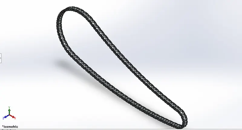
CHAIN
Chain is used to transmit mechanical power from engine to rear wheel. Roller chain is the commonly used type. The links were modelled as blocks and later imported.
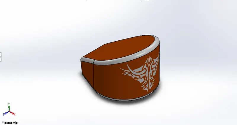
OIL TANK
Whether it is a car or a bike, a vehicles engine is depends on the fuel tank for continuous fuel supply. In the feature , it may be replaced by batteries in electric vehicles. Oil tank was modelled by using dynamic mirror entity and combine features. Shell features was used to make it hollow. It was a simple model.
PEDAL
A pedal is astrong rigid body and used to rest the foot while riding bikes. Splines, fillets, dome, and linear pattern were some of the featuers used to model the pedal.
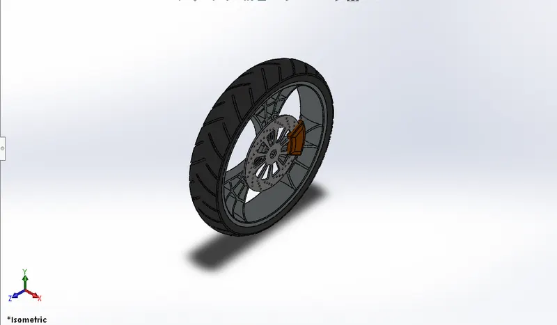
FRONT WHEEL
The front wheel experiences the greatest forces during braking.First the rim was created using revolve feature and spider webbed spokes were created by using arcs and offsets. Than rotor and caliper were modelled. Finally the wheel was created using revolve and treads were applied.
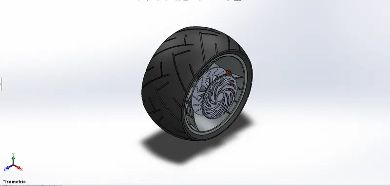
REAR WHEEL
The rear tier is primarily used for acceleration and propelling the motorcycle forward. It is wider than the front tire to improve stability of the bike. The steps followed for front wheel were used here. But this wheel has a rear sprocket as additional component It has varying dimensions.
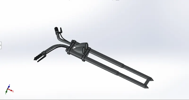
FRONT FORK
A bike fork is the part of a bike that holds the front wheel. A fork typically consists of two blades which are joined at the top by a fork crown. This was modelled by using features like extrude and mirror. Projected curves were used to model the handles and cables. A special appearance was given to the headlights that shows them glowing.
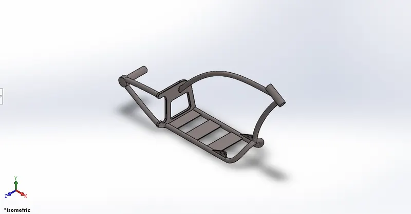
CHASSIS
A bike chassis or frame forms its skeleton. All the components of a bike are attached to this base structure which Lends a bike its strength and ability to handle well. Its modelling was started by using a picture as reference for sketching. It involved features like spline projected curves and split. It took more time to model.
ENGINE
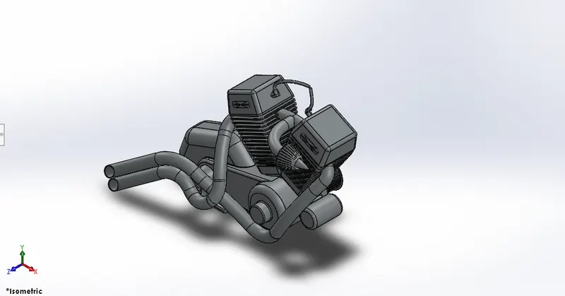
Engine is the heart of bike. It provides the poer necessary to drive the vehicle. A picture is imported for reference before modelling. First bottom part of the engine consisting of crank shaft motor and transmission pulleys was modelled. Than upper part of the engine with cooling fins are drawn. Than rear sprocket and air filter were modelled finally the exhaust system and spark plug were modelled using splines projected curves and sweep features.
GAS TANK
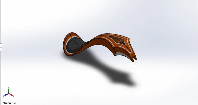
The gas tank covers the oil tank and engine and also acts as shield that prevents the heat from engine. The seat and opening for fuel tank are located on the top of gas tank. This also involved using a reference picture for sketching. One half of the tank was created and the mirrored. Than seat was modelled on the top of it and fillets were applied. Finally the tank was shelled to make it hallow.
ASSEMBLY OF THE AMEREICAN COPPER BIKE
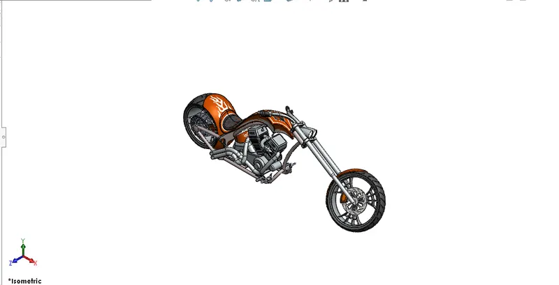
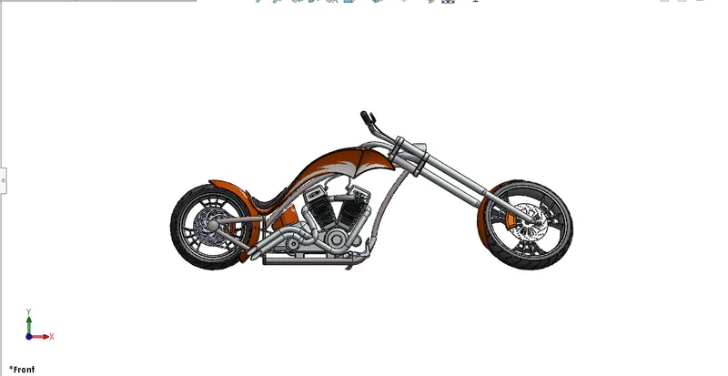
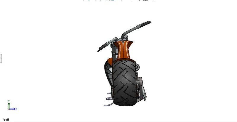
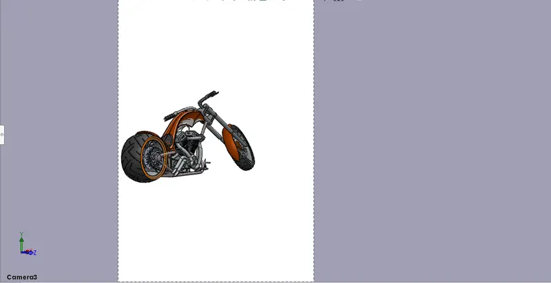
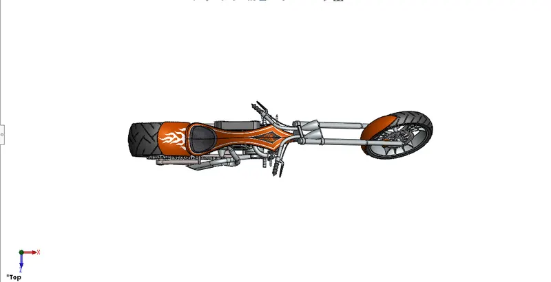
All the parts modelled were imported to assemble them. In assembly mate feature was used to locate and relate the parts with one another. Chassis was inserted initially and fixed. The other components were inserted and related to the chassis. Some parts were modified during assembly to make it perfect.
ISOMETRIC VIEW
FRONT VIEW
LEFT VIEW
CAMERA VIEW
TOP VIEW
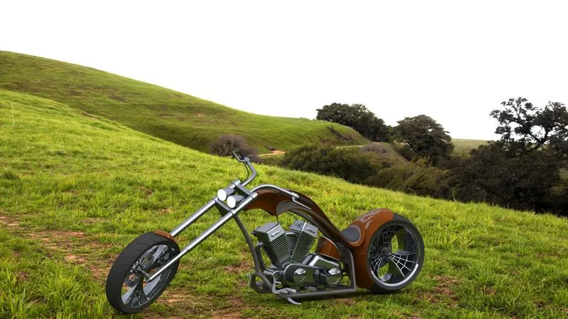
RENDERING OF THE AMERICAN CHOPPER BIKE
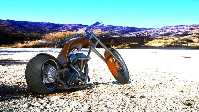
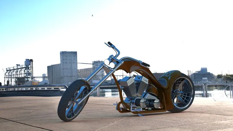
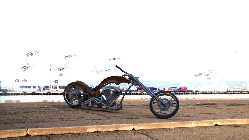
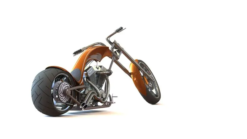
Rendering is a process creating realistic images of the photorealistic model with the environment. Renderings has done in two ways in soildworks . Photoview360 and Visulaize.
In this model i have done with Photoview 360
Photoview360 is a visualization and rendering solution includes with soildworks. Providing a highly interactive environment for viewing designs as well as for creating photorealistic rendering it can be used to showcase our designs as well.
RENDERING IMAGE 1.
RENDERING IMAGE 2.
RENDERING IMAGE 3.
RENDERING IMAGE 4.
RENDERING IMAGE 5.
CONCLUSION
The parts of the chopper are modelled
The realistic images was rendered with Photoview360
The parts are inserted into the assembly environment and the American chopper is assembled.
Knowledge about converting sketch into soild modeling.
Learned how to do sean setup and camera views.