Boeing-747 _ Final_Project
OBJECTIVE
The main objective is to create Surface modelling of different parts Boeing 747. The software is mainly used to model 3D parts using 2D sketch. It also tells about rendering of the model using Solidworks Visualize & Photo view360 to make the Boeing 747 more and realistic.
MODELLING & ASSEMBLING FEATURES
The various type modelling features used for modelling the BOEING 747 are discussed below.
SKETCH
Sketch is a two dimensional 2D into a solid modelling only when the 2D sketch completely closed .It also allows to extrude the surface in both direction and also offset it to require distance.
EXTRUDE
Using the solid works Surface Extrude feature, we can extrude the boundary edges of a face of a solid body or edges of a surface body in a customized direction.
REVOLVE
The revolve feature is used to revolve a 2D sketch along an axis or centreline and makes it a 3D model. A 2D sketch is drawn and revolved by selecting a line as a reference for axis of rotation and defining the angle of rotation.
LOFT
The loft feature allows you to generate complex geometry .It does this by interpolating surface between various cross section of the model. These cross sections can be sketches, faces or edges . In the loft interface the cross sections are considered as Loft profiles.
SWEEP
A sweep tool is used to sweep a closed 2D sketch along an open or closed path. This tool is generally used for making tubes and bars. A closed loop and a path sweep are required.
CHAMFER
A chamfer is used to remove a sharp edge by creating a sloped edges, vertex or face. Distance and angle of the chamfer are defined.
FILLET
A fillet is a tool used to round an edge, vertex or face on both inside and outside of 2D or 3D model. The fillet type, Location and radius of the fillet are defined.
EXTRUDE CUT
It is used to remove materials from a solid model in desired patterns and also it can be extruded with n=both directions.
COMBINE
Combine feature is used to combine two or more bodies when intersecting to each other and make it in a single body.
MIRROR
Mirror tool in solidworks is used to copy a 2D or 3D object about a reference line or plane. We can have either only the mirrored object or both the original and mirrored objects.
MATES
Mate is operation is the basic tool for assembling the parts, There are various mate operation such as coincident, parallel, perpendicular, tangent, concentric, lock, etc. We can two faces by defining distance or angle between them.
PROJECTED CURVES
A projected curve is a 3D curve that represents the intersection of two extruded surface of two sketches on intersecting planes.
LINEAR & CIRCULAR PATTERN
The Linear Pattern Command is used to drive features
, faces or bodies in a linear directions. The circular pattern command is an excellent tool used to replicate features, faces or bodies in a rotational manner about an axis.
SURFACE LOFT
Loft Surface are surfaces generated by multiple 3D Curves or existing edges creating a smooth tangency between the selected curves.
EXTRUDE SURFACE
Using the SOILDWORKS Surface Extrude feature, we can extrude the boundary edges of face of a solid body or edges of a surface body in a customizes direction.
SURFACE TRIM
To trim a surface Create two or more surface that intersect at one or more points, or create a surface that intersects with a plane or has a sketch on its face.
SURFACE SWEEP
Sweep Surface are surface that are generated from a section curve positioned along a path. Parallel Sweep is defined as a section curve moving along a guide path while maintaining the section curve to be parallel to the guide path.
DOME
The Softwere calculates the distance using the radius of the arc as a basis for the dome. It create a dome that is tangent to the adjacent cylindrical or conical face.
SURFCAE OFFSET
The Surface offset tool is useful way of creating a series of deposit or erosion contact surface from a reference mesh.
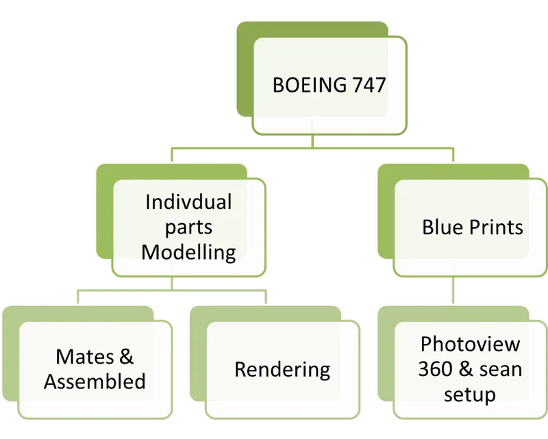
Design Flow chart of BOEING 747
MODELLING OF BOEING 747 PARTS
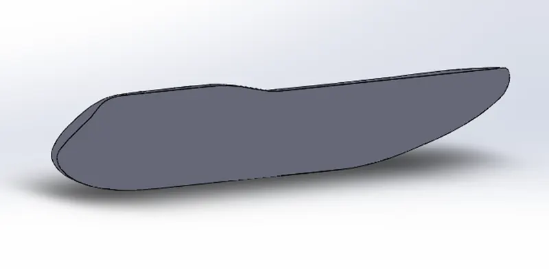
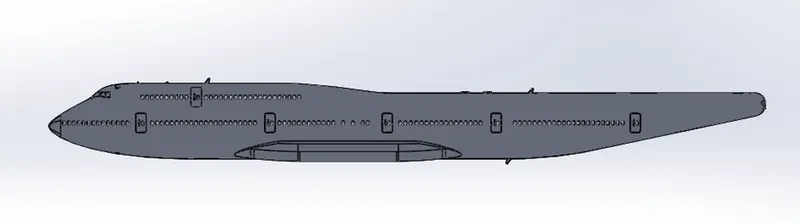
Fuselage
The fuselage, or body of the airplane, Is a long hollow tube which holds all the pieces of an airplane together. The fuselage is hollow to reduce weight. Passengers and cargo are carried in the rear of the fuselage and the fuselage and the fuel is usually stored in the wings.
COMMAND USED IN FUSELAGE
- Sketch
- Project Curve
- Surface Loft
- Planes
IMAGE
Belly Fairing
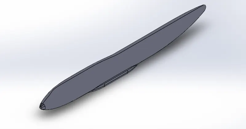
Belly fairing Also called a ventral fairing it is located on the underside of the fuselage between the main wings. It can also cover additional cargo storage or fuel tanks. Cockpit fairing also called a cockpit pod it protects the crew on ultralight trikes.
COMMAND USED IN BELLY FAIRING
- Sketch
- Split Line
- Fillet
- Mirror
- Split Line
IMAGE
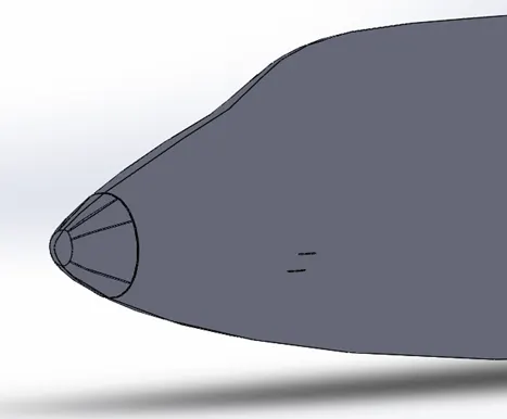
NOSE CONE
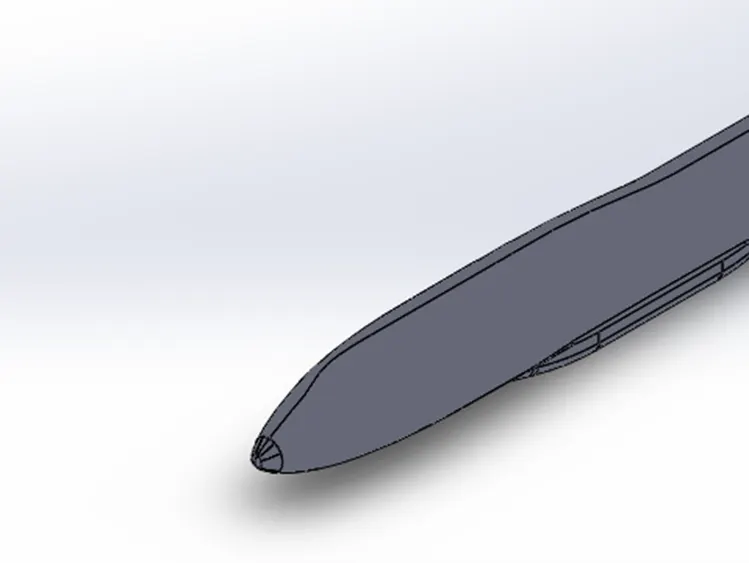
The nose cone and fins of plans are designed to minimise drag and to provide stability and control.
COMMAND USED IN NOSE CONE
- Sketch
- Split Line
- Fillet
- Mirror
- Sweep
- Split Line
IMAGE
PITOT TUBES
A Pitot probe tube also known as pitot probe, is a flow measurement device used to measure fluid flow velocity. It is widely used to determine the airspeed of an aircraft, water speed of a boat and to measure liquid air and gas flow velocities in certain industrial applications.
COMMAND USED IN PITOT TUBES PART
- Sketch
- Plane
- Axis
- Chamfer
- Fillet
- Sweep
- Revolve
- Extrude Cut
IMAGE
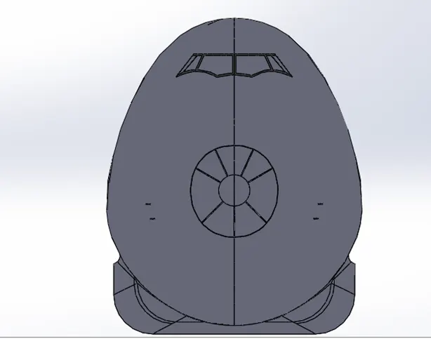
COCKPIT WINDOWS
Cockpit windows may be equipped with a sun shield Most cockpit have windows that can be opened when the aircraft is on the ground. Nearly all glass windows in large aircraft have an anti-reflective coating, and an internal heating element to melt ice.
COMMAND USED IN COCKPIT WINDOWS
- Sketch
- Split Line
- Thicken
- Fillet
- Mirror
IMAGE
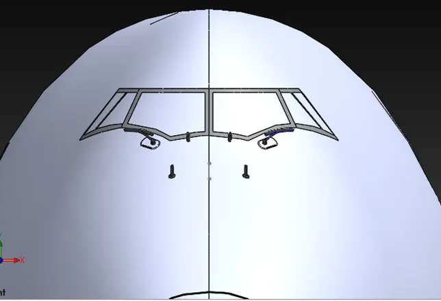
WIND SHIELD WIPER
The front of a boat is called the bow, while the rear of a boat is called the stern. When looking towards the bow, the left hand side of the boat is the port side. and starboard is the port side.
COMMAND USED IN WIND SHIELD WIPER
Windshield wiper are the most common rain protection feature. Most of them use electrical motors but some aircraft may be equipped with hydraulic wiper motors.
- Sketch
- Revolve
- Extrude
- Mirror
- Sweep
IMAGE
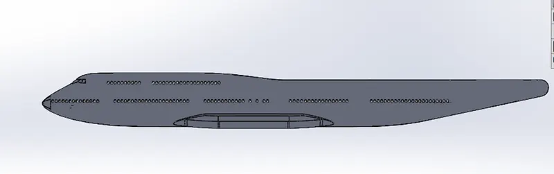
PASSENGER WINDOWS
Having windows allows passengers to see if there are threats to a particular side of the airplane.
COMMAND USED IN PASSENGER WINDOWS
- Sketch
- Split Line
- Fillet
IMAGE
DOOR AND HATCHES
The front of a boat is called the bow, while the rear of a boat is called the stern. When looking towards the bow, the left hand side of the boat is the port side. and starboard is the port side.
COMMAND USED IN DOOR AND HATCHES
- Sketch
- Surface offset
- Thicken
- Fillet
- Split Line
- Leaner Pattern
IMAGE
LIGHT AND ANTENNA
An aircraft antenna is a device that is used to navigate the aircraft by using radio frequencies. It is used to communicate with other aircraft as well as ground based control stations.
COMMAND USED IN LIGHT ANTENNA
- Sketch
- Split Line
- Draft
- Pattern
- Surface offset
- Thicken
IMAGE
AUXILLARY POWER UNIT
The auxilliary power unit is a small gas turbine engine mounted in the tail cone of an aircraft to provide autonomous electrical and mechanical power for the main engines.
COMMAND USED IN AUXILLARY POWER UNIT
- Boss Extrude
- Sketch
- Split Line
- Pattern
- Surface offset
- Thicken
IMAGE
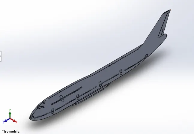
VARTICAL STABILIZER
At the rear of the fuselage of most aircraft one finds a vertical stabilizer an a rudder. The stabilizer is a fixed wing section whose job is to provide stability for the aircraft.
COMMAND USED IN VARTICAL STABILIZER
- Boss Extrude
- Sketch
- Split Line
- Fillet
- Plane
IMAGE
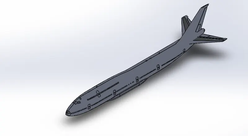
HORIZONTAL STABILIZER
At the rear of the fuselage of most aircraft one finds a horizontal stabilizer and an elevator.T he stabilizer is affixed wing section whose job to provide stability for the aircraft, to keep it flying straight.
COMMAND USED IN HORIZONTAL STABILIZER
- Boss Extrude
- Sketch
- Split Line
- Fillet
- Curve
- Surface Offset
- Plane
IMAGE
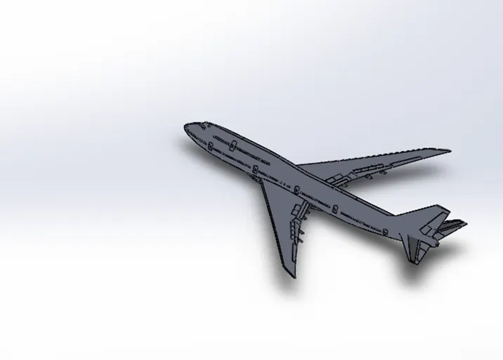
WING
Wing is aeronautics, an airfoil that helps lift a heavier than air craft. When positioned above the fuselage wings provide an unrestricted view below and good lateral stability.
COMMAND USED IN WING
- Boss Extrude
- Sketch
- Split Line
- Fillet
- Curve
- Surface Offset
- Plane
IMAGE
 .
.
FLAPS AND AILERONS
Ailerons are panels on the trailing edge of the wing near the tips that move up and down.
COMMAND USED IN FLAPS AND AILERONS
- Thicken
- Sketch
- Split Line
- Fillet
- Curve
- Surface Offset
- Plane
IMAGE
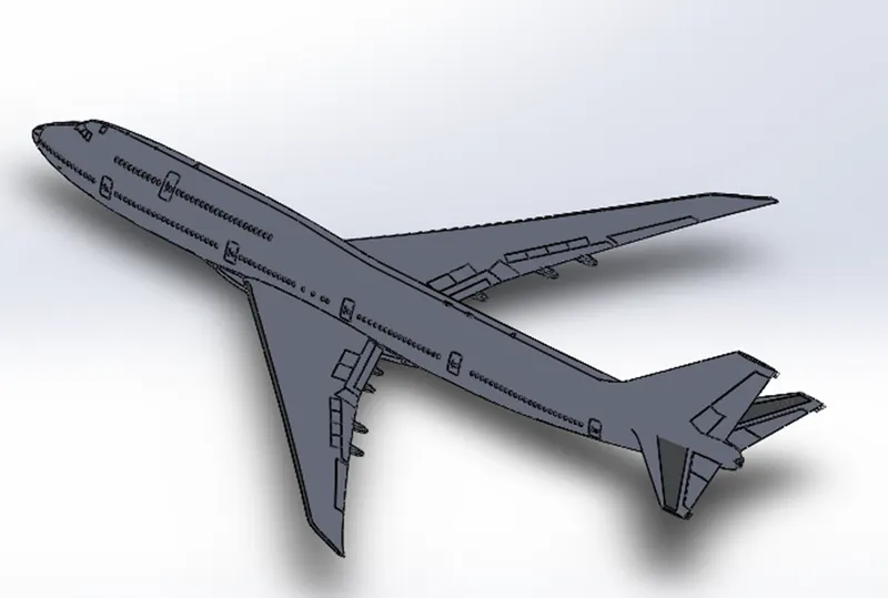
FLAP TRACK FAIRINGS
A flap is a high –lift device used to reduce the stalling speed of an aircraft wing at a given weight.
COMMAND USED IN FLAPS TRACK FAIRING
- Thicken
- Sketch
- Split Line
- Fillet
- Boss extrude
- Surface Offset
- Mirror
IMAGE
LANDING GEAR AXIS
For Reference.
IMAGE
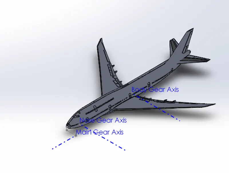
LANDING GEAR HATCHES OPEN
There are 4 basic categories of landing gear that general aviation planes use.
COMMAND USED IN LANDING GEAR HATCHES OPEN
- Thicken
- Sketch
- Split Line
- Fillet
- Surface Offset
- Mirror
IMAGE
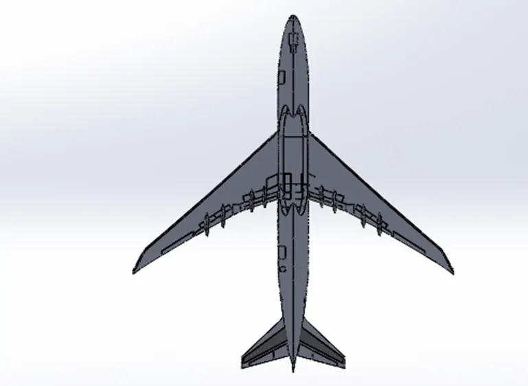 .
.
WHEEL
The wheels of a plane are called the landing gear. There are two main wheels on either side of the plane fuselage. Then there is one more wheel near the front of the plane. The brakes for the wheels are like the brakes for cars.
COMMAND USED IN WHEEL
- Sketch
- Chamfer
- Fillet
- Revolve
- Mirror
- Dome
- Extrude
IMAGE
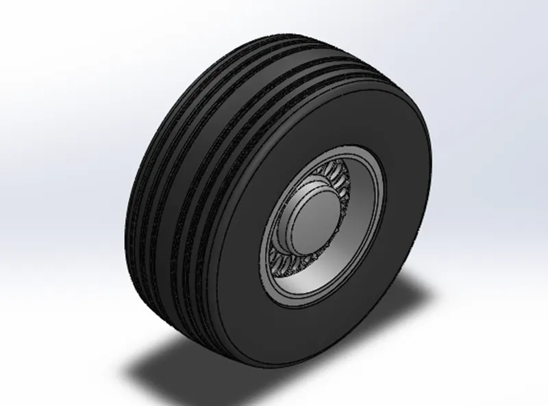
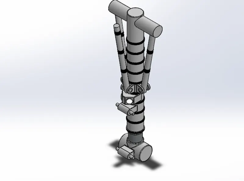
NOSE GEAR BASE
Nose gear is the name given to the landing gear in the nose of an airplane.
COMMAND USED IN NOSE GEAR BASE
- Sketch
- Chamfer
- Fillet
- Revolve
- Mirror
- Dome
- Extrude
- Split Line
- Cut Extrude
IMAGE
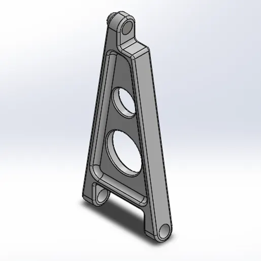
NOSE GEAR SUSPENSION ARM
Nose gear is the name given to the landing gear in the nose of an airplane.
COMMAND USED IN NOSE GEAR SUSPENSION ARM
- Sketch
- Chamfer
- Fillet
- Mirror
- Extrude
- Split Line
- Cut Extrude
IMAGE
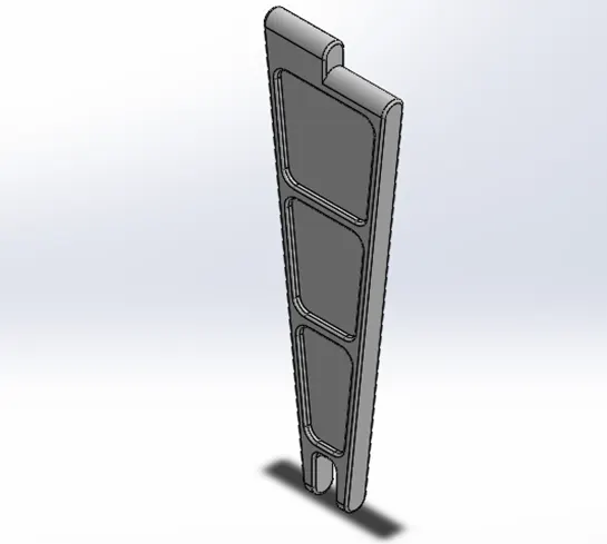
MAIN GEAR SUSPENSION ARM
The purpose of the landing gear in an aircraft is to provide a suspension system during taxi take- off and landing. It is designed to absorb and dissipate the kinetic energy of landing impact.
COMMAND USED IN MAIN GEAR SUSPENSION ARM
- Sketch
- Chamfer
- Fillet
- Mirror
- Extrude
- Split Line
- Cut Extrude
IMAGE
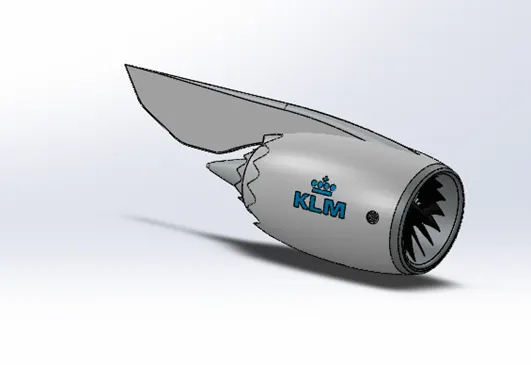
ENGINE
An aircraft engine, often referred to as aero engine, is the power component of an aircraft propulsion system. Most aircraft engines are either piston engines or gas turbines although a few have been rocked powered and in recent years many small UAVs have used electric motors.
COMMAND USED IN ENGINE
- Sketch
- Chamfer
- Fillet
- Mirror
- Extrude
- Split Line
- Cut Extrude
- Revolve
- Combine
IMAGE
LIVERY
An aircraft livery is a set of comprehensive insignia comprising colour graphic and typographical identifiers which operators occasionally private and corporate owners apply to their aircraft.
COMMAND USED IN ENGINE
- Sketch
- Mirror
- Split Line
IMAGE
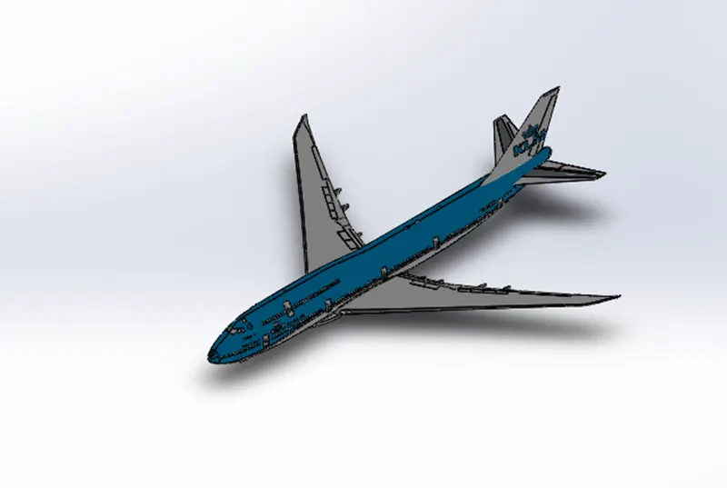
ASSEMBLY OF THE BOEING 747
All the parts modelled were imported to assemble them. In assembly mate feature was used to locate and relate the parts with one another. Desk was inserted initially and fixed. The other components were inserted and related to the Desk.
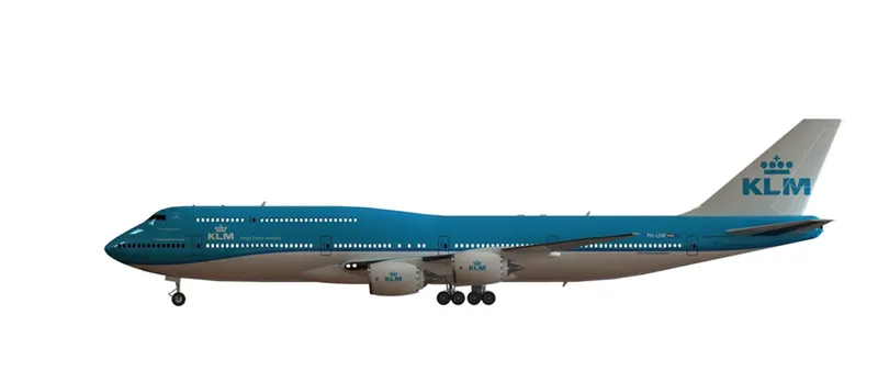
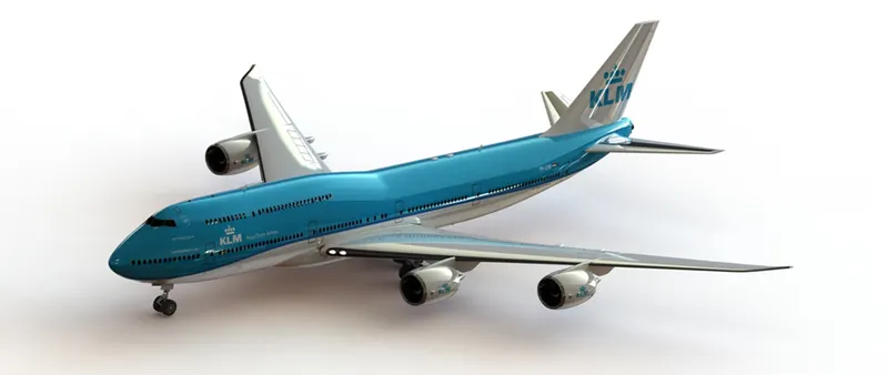
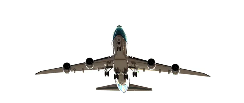
RENDERING OF THE BOEING 747
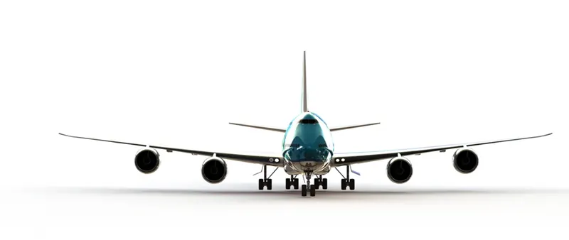
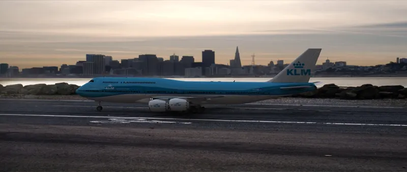
Rendering is a process creating realistic images of the photorealistic model with the environment. Renderings has done in two ways in soildworks . Photoview360 and Visulaize.
In this model i have done with Photoview 360
Photoview360 is a visualization and rendering solution includes with soildworks. Providing a highly interactive environment for viewing
designs as well as for creating photorealistic rendering it can be used to showcase our designs as well.
CONCLUSION
The parts of the BOEING are modelled
The realistic images was rendered with Photoview360
The parts are inserted into the assembly environment and the YBOEING 747 is assembled.