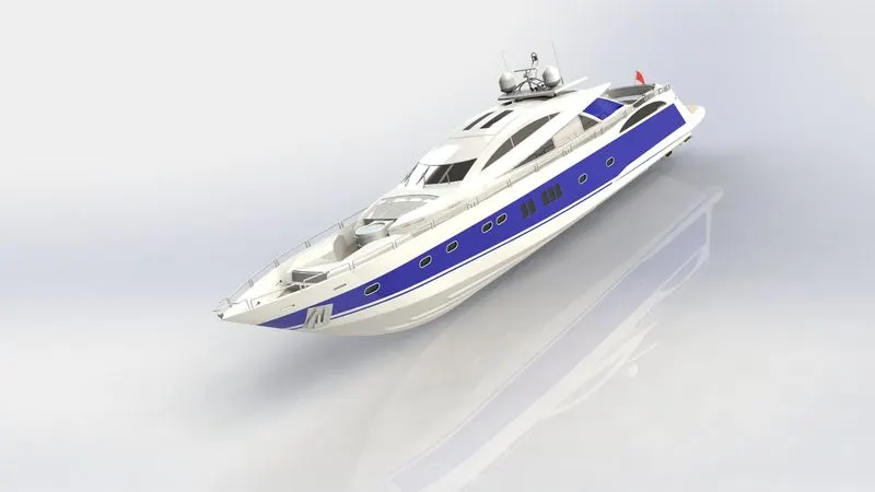
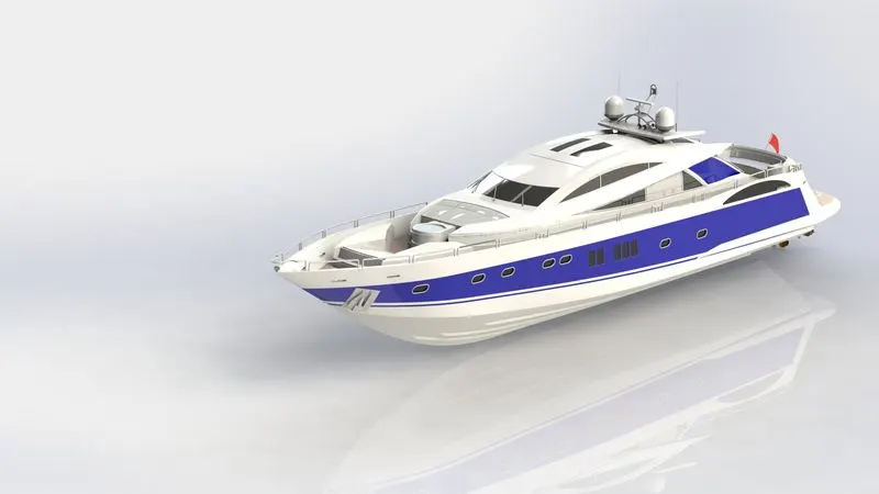
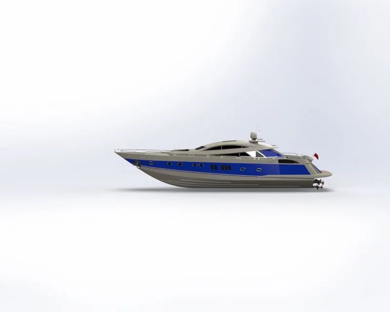
Radar Mast & Final Assembly of Yacht
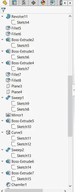
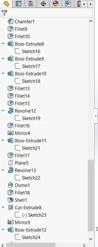
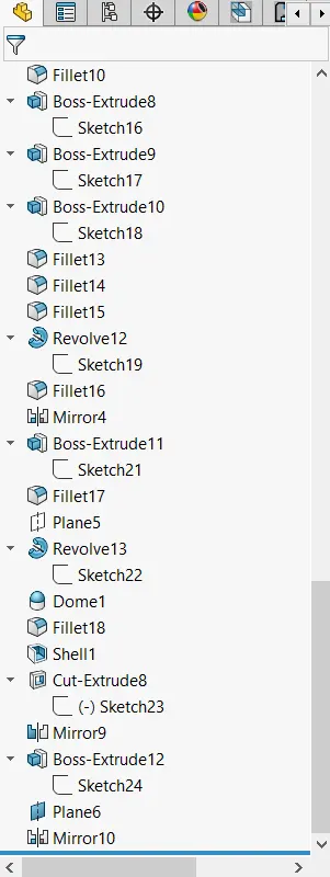
1. Radar Mast
Front
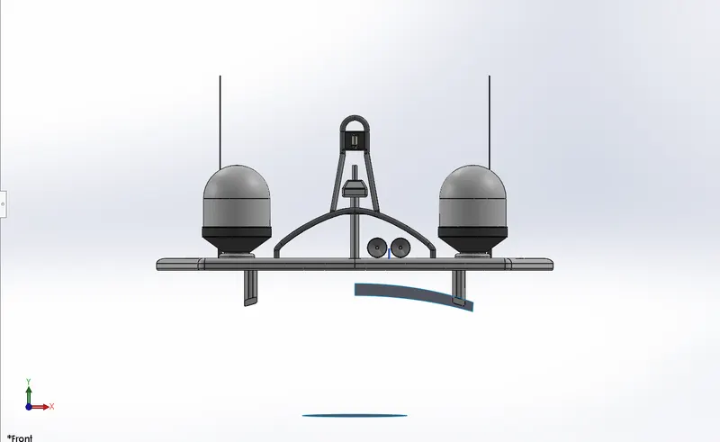
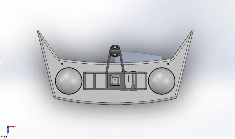
TOP
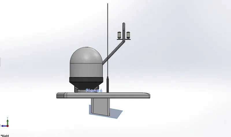
SIDE
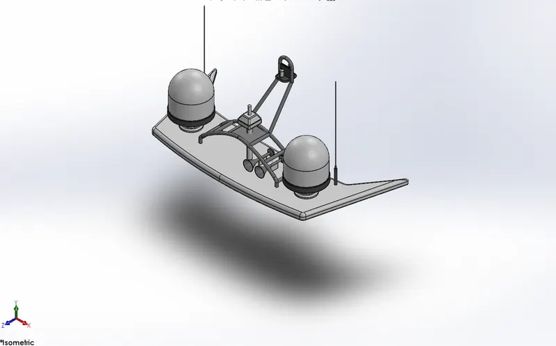
ISO
2. Yacht Assembly
FRONT
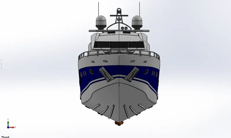
TOP
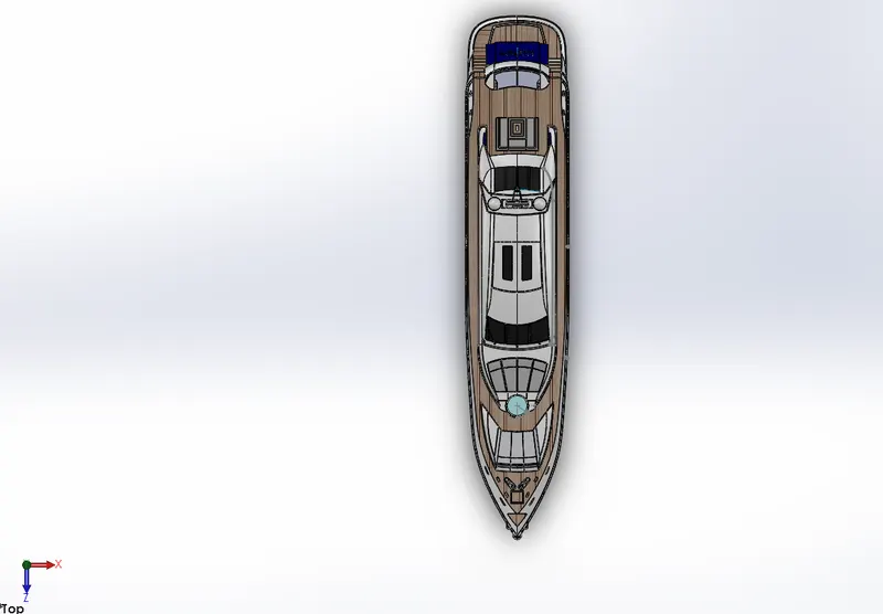
SIDE
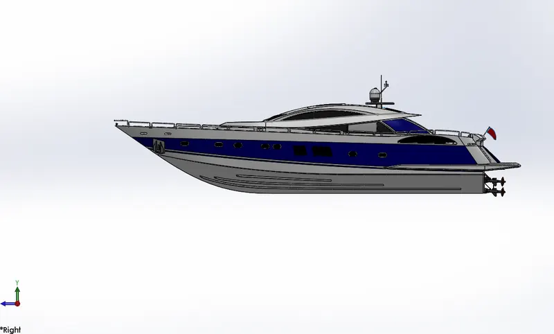
ISO
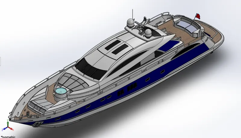
Report on Sun Seeker Predator Yacht
- To design individual parts of the yacht with fully defined sketches and appropriate appearances.
- How to assemble different parts of the Sunseeker Predausing yacht
- Creating a rendered image using Photo View 360.
- To render the yacht model by adding appearances, decals, lights, cameras, and background scenes.
Software's Used:
- Solid-works 2021.
- Solid-works Visualize 2021.
Introduction:
Solid-works: Solid works is a product of Dassault systems. It is a software used for designing, assembling and real time rendering of the real time models. Any kind of complicated and sensitive designs can be easily modeled using the tools and interface of this software. The basic tools and its usage are explained in the description section
Yacht:Sunseeker Yachts’ legacy began in the 1970s on the British south coast in Poole, England. Formally known as Poole Power Boats, Sunseeker was founded by Robert and John Braithwaite.
New hulls and extravagant designs ushered the name change in the 1980s. Business skyrocketed after an encounter with an Englishman who suggested design tweaks, which led to the birth of the modern luxury motor yacht.
Design methodology Flowchart:
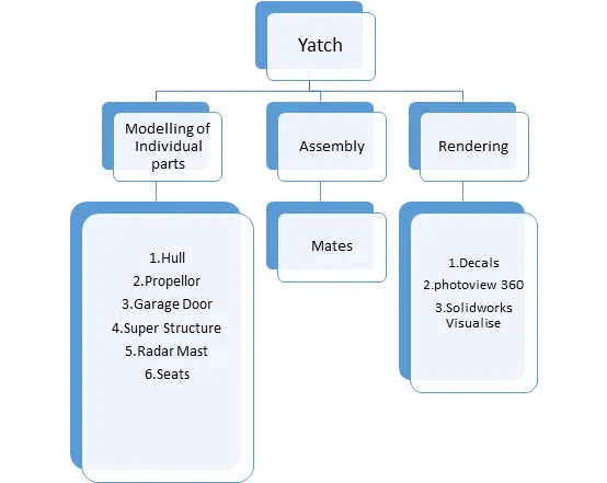
Parts of yacht
- Hull
- Superstructure
- Radar mast
- Rear seat
- Middle seat
- Front seat
- Radar
- Garage door
- Propeller
TOOLS AND FEATURES:-
- Sketch tool.
- Sketch pattern
- Convert entities
- Offsets entities
- Extrude Boss/Base
- Revolved Boss/Base
- Sweep Boss/Base
- Circular pattern
- Extrude cut
- Fillet/chamfer
- Shell
- Reference plane
- Projected curves
- Extrude surface
- Swept surface
- Lofted surface
- Fill surface
- Offset surface
- Ruled surface
- Knit surface
- Circular pattern
Design Process
The entire modelling process is divided in to Six Stages
- Blue Print Setup & Creating Planes.
- Modelling of Hull Part
- Modelling of Super Structure
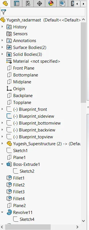
- Modelling of Radar Mast
- Modelling of front, middle & Rear Seats.
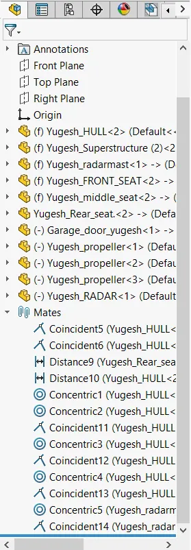
- Assembling the individual parts.
Design and Methodology
Blueprint Setup:
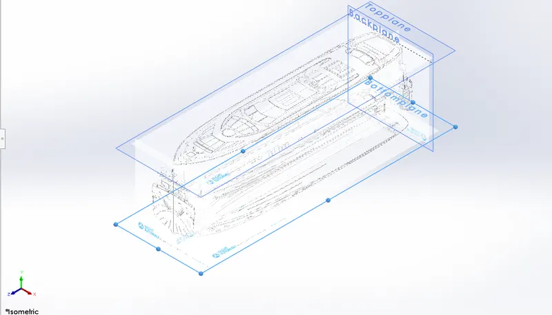
Methodology
-Select a Plane & select a 2d drawing option & go to Tools- Sketch Tool-Sketch Picture.
- Browse the Image & change the dimensions as per requirement & use transparency tab & chose full image for convenient sketching & name the views
- Repeat the above steps & name it as Front view, side view, Top view, Back view.
- change the names of the planes as front plane, bottom plane & mid plane & Arrange the blue prints in a sequential order.
- PROPELLER
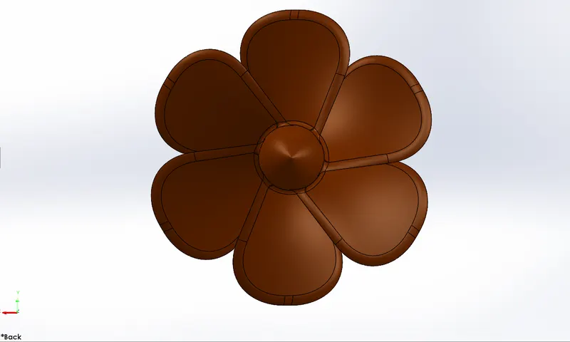
- REVOLVE/BOSS
This feature helps to revolve the open sketch as well as closed sketch with the help of one axis.
- LOFT EXTRUDE
Surface generated by existing edges creating a smooth tangent between the selected curves.
- FILLET
Fillets are used to create a smooth curve on the profile or at the edges. For this constant size, fillet is used.
- CIRCULAR PATTERN
For this feature one selection of face is required and selections of equal spacing with required angle and number of instances.
- EXTRUDE CUT
This is used to remove the material from the solid model with the required depth or draft.
2.RADAR
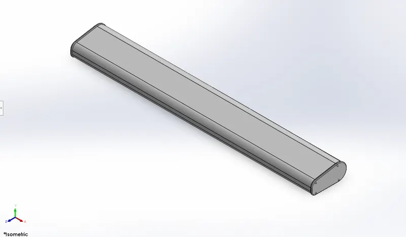
- EXTRUDE BOSS/BASE
This feature is used only when the sketch is closed and then extruded to the required height.
- FILLET
Fillets are used to create a smooth curve on the profile or at the edges. For this constant size fillet is used.
- EXTRUDE CUT
This is used to remove the material from the solid model with the required depth or draft.
- SKETCH PATTERN
In this feature selection of faces is required to create multiple faces by selecting 2D sketches.
- MIRROR
This is the replica of one solid body by selecting a plane or by the solid body face. In this mirror, it has an option to create as a single body and to knit it.
- EXTRUDE CUT
This is used to remove the material from a solid model with the required depth or draft.
3. HULL
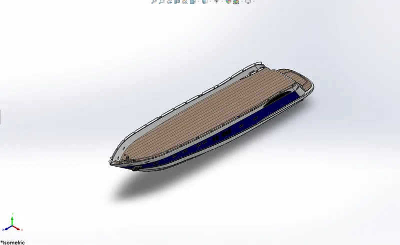
PROJECTED CURVE
This sketch is used as a 3D curve on the profile. This curve can be achieved by two different line or splines which starts from same direction and ends in the same direction with two different planes.
SURFACE LOFT
This will not create any solid body It creates only 0 thickness profile by selecting the line or spline as profile and guide curve.
SURFACE TRIM
Feature is applicable for surface modeling only not for solid modeling. It trims on the surface with the help of sketch entities only.
SURFACE EXTRUDE
With an open sketch also the surface extrude can be done, it need not be a close sketch. Again this feature works with surface modeling only.
KNIT
Knit is used to reduce the gap between the two surfaces.
SURFACE FILL
Surface fill is similar to surface loft.
SHELL
Shell is used to create a hollow profile by selecting the face or body with the required thickness.
- EXTRUDE CUT
This is used to remove the material from the solid model with the required depth or draft.
- EXTRUDE BOSS/BASE
This feature is used only when the sketch is closed and then extruded to the required height.
- FILLET
Fillets are used to create a smooth curve on the profile or at the edges. For this constant size, fillet is used.
- MIRROR
This is the replica of one solid body by selecting a plane or by the solid body face. In this mirror, it has an option to create as a single body and to knit it.
4. FRONT SEAT
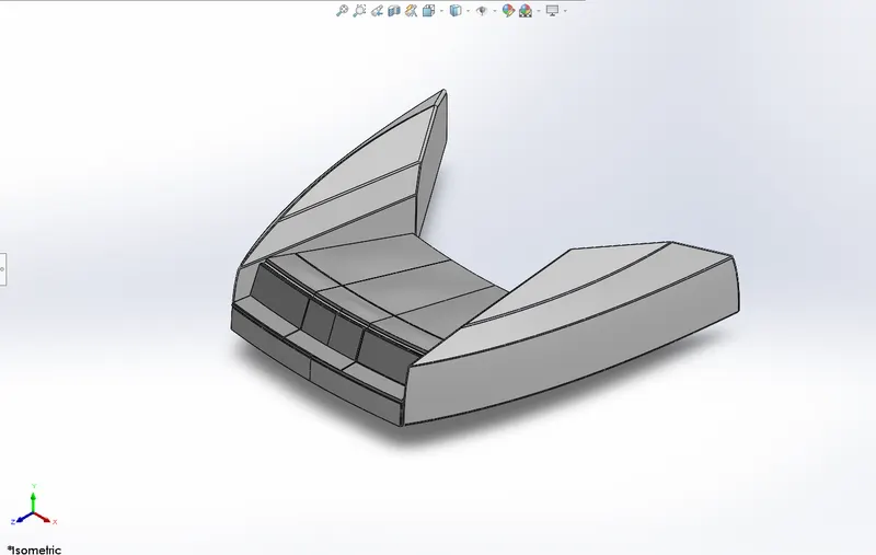
SURFACE EXTRUDE
With an open sketch also the surface extrude can be done, it need not be a close sketch. Again this feature works with surface modeling only.
FILLET
Fillets are used to create a smooth curve on the profile or at the edges. For this constant size, fillet is used.
SURFACE LOFT
This will not create any solid body It creates only 0 thickness profile by selecting the line or spline as profile and guide curve.
SURFACE TRIM
Feature is applicable for surface modeling only not for solid modeling. It trims on the surface with the help of sketch entities only.
KNIT
Knit is used to reduce the gap between the two surfaces.
REVOLVE/BOSS
This feature helps to revolve the open sketch as well as closed sketch with the help of one axis.
SURFACE SWEEP
It is the same as sweep boss but in surface modeling surface sweep is used by selecting the profile and the part for the sweep.
DOME
This creates a smooth tangent curve on the face of the body.
5. MIDDLE SEAT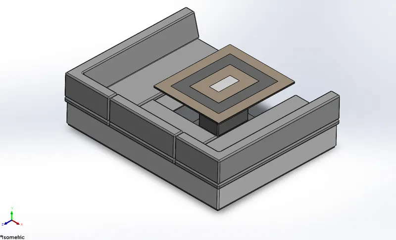
EXTRUDE BOSS/BASE
This feature is used only when the sketch is closed and then extruded to the required height.
FILLET
Fillets are used to create a smooth curve on the profile or at the edges. For this constant size, fillet is used.
MIRROR
This is the replica of one solid body by selecting a plane or by the solid body face. In this mirror it has an option to create as a single body and to knit it.
EXTRUDE CUT
This is used to remove the material from the solid model with the required depth or draft.
6. REAR SEAT
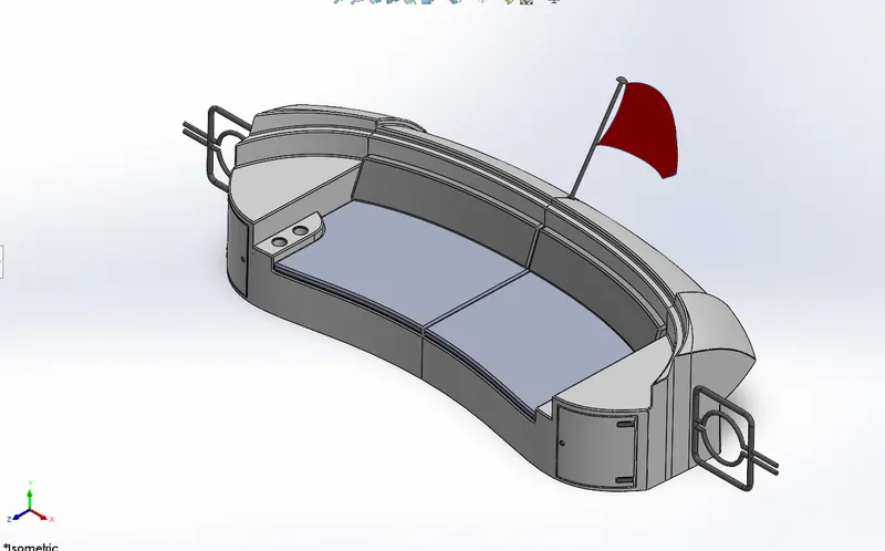
SURFACE SWEEP
It is the same as sweep boss but in surface modeling surface sweep is used by selecting the profile and the part for the sweep.
SURFACE TRIM
Feature is applicable for surface modeling only not for solid modeling. It trims on the surface with the help of sketch entities only.
SURFACE EXTRUDE
With an open sketch also the surface extrude can be done, it need not be a close sketch. Again this feature works with surface modeling only.
KNIT
Knit is used to reduce the gap between the two surfaces.
SURFACE LOFT
This will not create any solid body It creates only 0 thickness profile by selecting the line or spline as profile and guide curve.
FILLET
Fillets are used to create a smooth curve on the profile or at the edges. For this constant size, fillet is used.
MIRROR
This is the replica of one solid body by selecting a plane or by the solid body face. In this mirror, it has an option to create as a single body and to knit it.
SURFACE OFFSET
This creates an equal distancing with the selected surface with required dimensions, this feature is used only in surface modeling.
RULED SURFACE
Ruled surface create a tapered curved surface with the help of a single edge with a specified distance
EXTRUDE CUT
This is used to remove the material from the solid model with the required depth or draft.
EXTRUDE BOSS/BASE
This feature is used only when the sketch is closed and then extruded to the required height.
7. SUPERSTRUCTURE
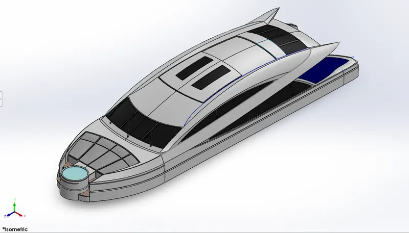
SURFACE EXTRUDE
With an open sketch also the surface extrude can be done, it need not be a close sketch. Again this feature works with surface modeling only.
SURFACE SWEEP
It is the same as sweep boss but in surface modeling surface sweep is used by selecting profile and the part for the sweep
KNIT
Knit is used to reduce the gap between the two surfaces.
FILLET
Fillets are used to create a smooth curve on the profile or at the edges. For this constant size, fillet is used.
SURFACE LOFT
This will not create any solid body It creates only 0 thickness profile by selecting the line or spline as profile and guide curve.
SURFACE TRIM
Feature is applicable for surface modeling only not for solid modeling. It trims on the surface with the help of sketch entities only.
RULED SURFACE
Ruled surface creates a tapered curved surface with the help of a single edge with a specified distance.
8. RADARMAST
- EXTRUDE BOSS/BASE
This feature is used only when the sketch is closed and then extruded to the required height
- FILLET
Fillets are used to create a smooth curve on the profile or at the edges. For this constant size, fillet is used.
SURFACE SWEEP
- It is the same as sweep boss but in surface modeling surface sweep is used by selecting the profile and the part for the sweep.
DOME
- This creates a smooth tangent curve on the face of the body.
REVOLVE/BOSS
- This feature helps to revolve the open sketch as well as closed sketch with the help of one axis.
MIRROR
- This is the replica of one solid body by selecting a plane or by the solid body face. In this mirror, it has an option to create as a single body and to knit it.
SHELL
- Shell is used to create a hollow profile by selecting the face or body with the required thickness.
Final Rendering:
In this our Yacht Assembly rendered to make it more realistic using Solid-works
Methodology
o Import - Import assembly once created a new project.
o Appearance - Give appropriate appearances to various parts to make more attractive after rendering.
o Scenes - Use Proper Back Plates/Environment as scenes and drag the assembly at proper location.
o Decals: Graphics or designs used
o Lights & cameras. To adjust lighting and set camera
o Output - Once done with all setup, a quick render helps you out to review final output. Changes the colours by increasing/decreasing various values for better look (if required). Then go for final quality rendering