Radar Mast & Final Assembly of Yacht
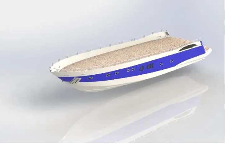
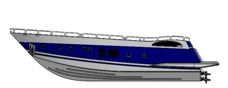
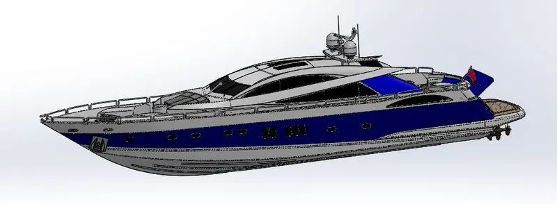
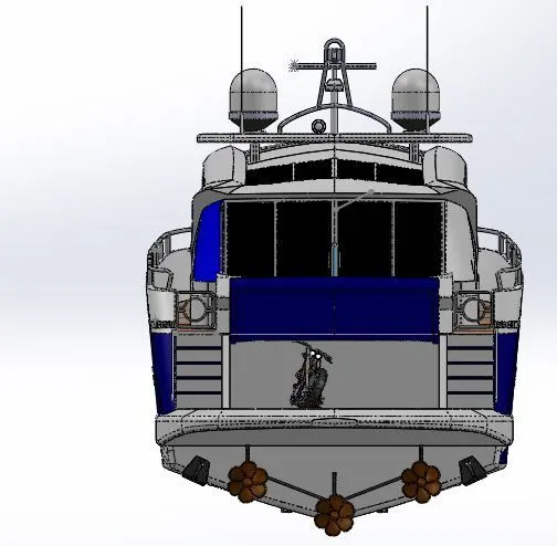
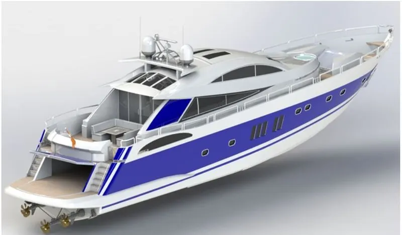
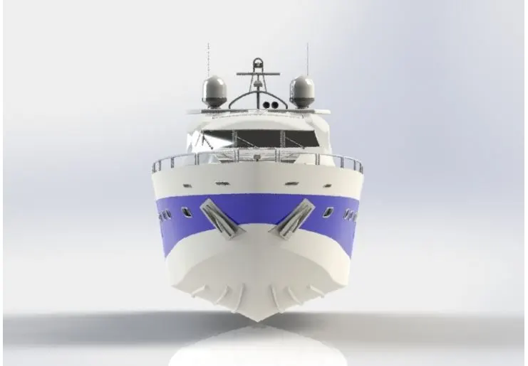
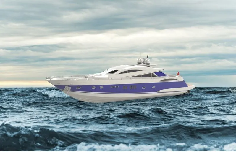
Photorealistic rendering of Sunseeker Predator Yatch
AIM AND OBJECTIVE:
- The aim and objective are to design and assemble various parts using Solidworks.
INTRODUCTION:
- The Yatch assembly comprises part modeling as well as surface modeling.
- To model the Sunseeker Predator Yacht by using the surface modeling feature.
PARTS TO BE MODELLED:
- Propeller
- Radar
- Hull
- Garage Door
- Rear Seat
- Front Seat
- Middle Seat
- Superstructure
- Radar Mast
Propeller :
A propeller is a fan-like structure that is used to propel the ship by using the power generated and transmitted by the engine of the ship. The transmitted power is converted from rotational motion to generate a thrust which imparts momentum to the water resulting in a force that acts on the ship and pushes it forward.
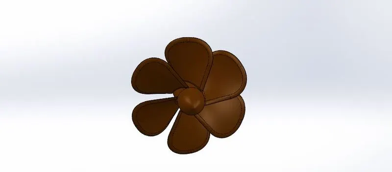
Features used to create Propeller:
- Sketch
- Revolve
- Lofted Base
- Cut Extrude
- Fillet
- Circular Pattern
Sketch:
- The sketch is basically a 2D representation of a particular form of different views such as front view, side view, top view, etc. The sketch comprises of commands like lines, arcs, circles, etc.
Revolve:
- Revolve is the process of creating a revolved profile with reference to the sketch and the axis of the rotation. The profile can be created with the revolution up to 360-degree axis rotation.
Lofted Base:
- Creates a 3D solid or surface bi specifying a series of cross-sections. The cross-section defines the shape of the resulting solid or surface. You must at least specify two cross-sections. Loft cross-sections can be open or closed, planar and non-planar, can also be edge sub-objects.
Cut Extrude:
- The extrude cut feature is used to remove the unwanted materials as per the modeling sketch.
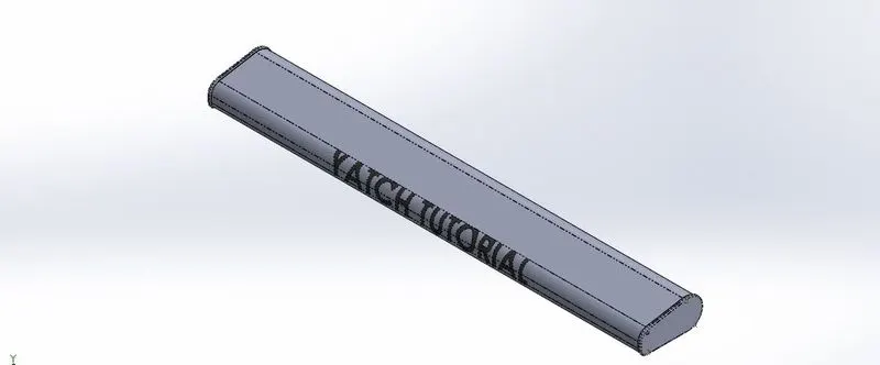
Radar:-
An electronic detection system that sends electromagnetic waves to detect angle, range, the velocity of an object like a ship, submarines, aircraft, spacecraft, etc.
In modeling of Radar, we used the following tools.
Feature Tool: - Boss Extrude, Fillet, Cut Extrude, Mirror.Split line
Sketch tool: - Sketch entities, Sketch Pattern.
No. of Solid Bodies: - 1
Sketch Pattern: - It patterns features, faces, and bodies based on sketch points.
Split line:- This creates a breakpoint online to make a segment into two.
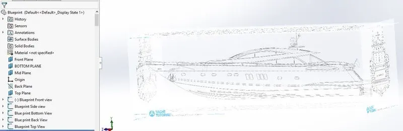
1. Blueprint Setup
This is the first step to start the model, using blueprints. In this part, all the blueprints of yacht are fixed to their respective planes. Such as the blueprint of the front view of the yacht is fixed on the Front plane, the side view is fixed on the midplane, the top view is fixed on the top plane, the back view is fixed on the backplane & the bottom view is fixed on the bottom plane. Two planes are manually created using the reference geometry feature & named as backplane and top plane. Here top plane is renamed as the bottom plane & the right plane is named as midplane.
HULL:
A Hull is watertight of a ship or boat. The Hull may open at the top of it may be fully or partially covered with a deck. The line where the Hull meets the water surface is called the waterline.
Features used to create Hull:
- Sketch
- Project Curve
- Loft Surface
- Surface Extend
- Fill Surface
- Surface Extrude
- Surface Trim
- Shell
- Bose Extrude
- Cut Extrude
- Fillet
- Chamfer
- Sweep
- Plane
- Dome
- Helix/Spiral
- Linear Pattern
- Delete Face
- Curve
- Revolve
- Combine
Project Curve:
- The projected curve will be available under the feature tab. The project curves command can be used to create a 3D curve. The 3D curve can be created by using the reference of two 2D curves.
Fill Surface:
- Creates a surface patch within the boundary defined by existing model edges, sketches or curves.
Surface Extrude:
- Creates an extruded surface based on the sketch.
Surface Extend:
- Extend the edge, multiple edges, or face on a surface based on end condition and extension type.
Surface Trim:
- The Surface Trim is used to trim the surface where one surface interacts with another surface, plane, or sketch.
Shell:
- The shell command is used to thickened the surface either it can be done in the interior or exterior surface.
Chamfer:
- The Chamfer command creates a beveled feature on the edge, face, or vertex.
Sweep:
- The sweep command is used to create solid by sweeping a closed profile along an open or closed path.
Dome:
- Dome, in architecture, the hemispherical structure evolved from the arc, usually forming ceiling or roof over the surface or face being selected.
Helix/Spiral:
- This command creates a spiral or helix based on some reference sketch.
Delete Face:
- This command is used to delete unnecessary faces and this feature comes with some options like delete a face, delete and patch, delete and fill.
Combine:
- The Combine feature is used to create a single solid body from a number of existing individual solid bodies
Garage door
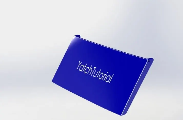
It is an extracted part of the hull, which is used as the base of the garage door. The garage door is consists of the following solid features:
Cut extrude - used to cut the extracted part of the hull.
Shell - used to hollow the solid body with some thickness.
Fillet - used to give the round shape to corners & edges.
Mirror - used to mirror the half portion of the hull.
FRONT SEAT :
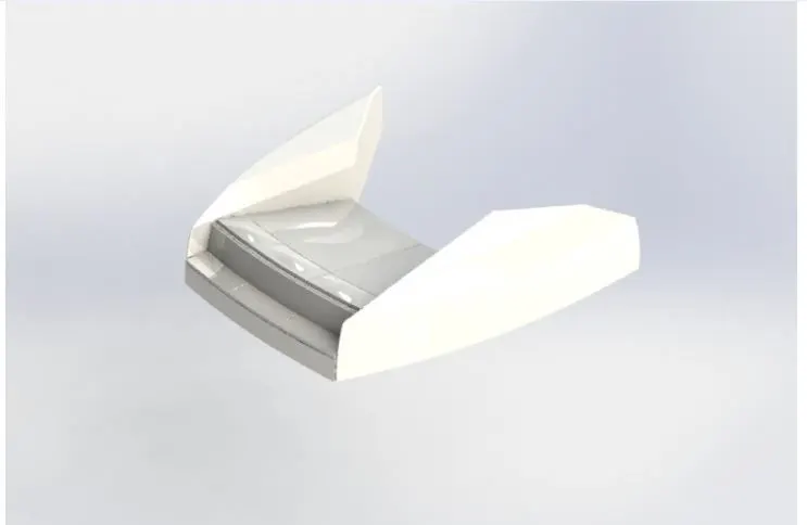
- The Seat is a thing which is used for sitting purposes. The Front Seat is built on the front side of the Yatch.
Features used to create Rear Seat:
- Sketch
- Surface Sweep
- Surface Trim
- Dome
- Surface Loft
- Surface Extrude
- Surface knit
- Fillet
- Chamfer
- Revolve
- Mirror
Middle Seat:-
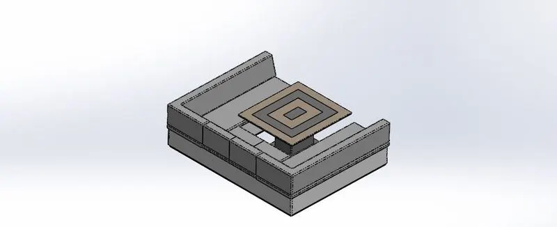
The middle seat is situated next to the superstructure. It is modeled with reference to the deck surface.
Feature tools: - Boss Extrude, Cut Extrude, Mirror, Fillet, Chamfer.
Sketch tools :-Sketch Entities, Convert Entities, Offset Entities.
No. of Solid Bodies: - 8
No. of Surfaces Bodies: - 1
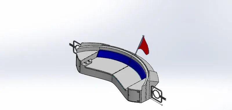
Rear seat
In the rear seat part, the offset surface of the hull is used as a base reference. It consists of the following features:
Surface sweep – used to sweep the surface.
Surface offset – used to offset the surface.
Surface trim– used to trim the surface.
Ruled surface – used to extend the surface at an angle using a curve or line.
Surface knit - used to knit two or more than two surfaces.
Surface extrude - used to extrude the surface.
Surface extend – used to extend the surface.
Surface loft - used to create a surface using at least 2 profile curves & 2 guide curves.
Boss extrude - used to create a solid body from 2D sketch.
Sweep - used to form helical shape & pipe using a profile sketch & guide curve to give a path to the profile sketch.
Revolve – used to revolve a closed sketch about an axis by giving one of the lines as an axis.
Fillet - Used to give a round shape to the corners & edges.
Chamfer - Used to give a round shape to the corners & edges.
Mirror - used to mirror the half portion of the rear seat to the opposite side.
Superstructure:-
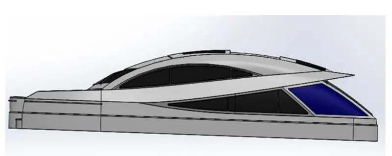
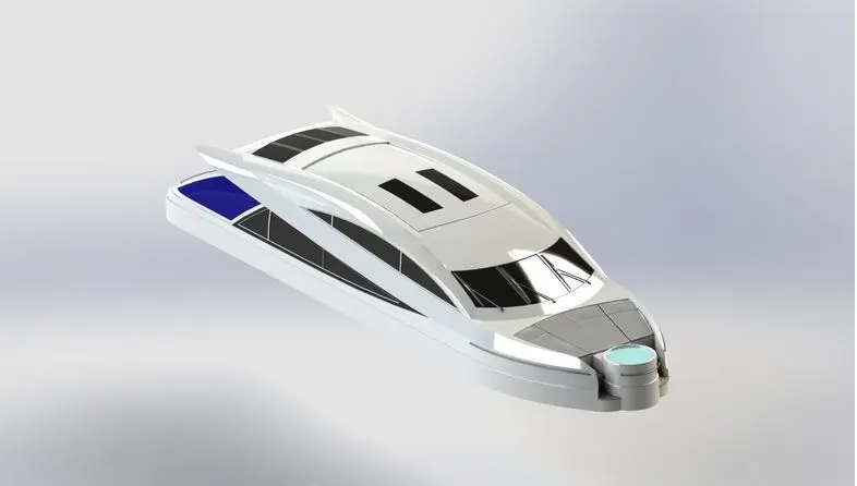
It is the extension above the deck surface of the hull which houses accommodation, offices, Signal and Communication unit, utility spaces, and multifarious electrical and electronic system areas which are indispensable to the operation and the functionality of the ship as well as the sustainability of crew. A good superstructure serves the following objectives
- Fulfillment of operational requirement in terms of available volume
- Provision of enough height and space of deck.
In the design of a superstructure, height plays a crucial part. The height of must be enough to provide a proper navigational line of sight also it must be within the limit of stability.
In the design of the superstructure, we used the following tools,
Feature tools: -3D sketch, Projected Curve, Boss Extrude, Cut Extrude, Chamfer, Fillet, Mirror, Dome.
Sketch tools :-Sketch entities, Trim Entities, Offset Entities, Convert entities.
Surface tools:- Inset Surface, Extrude Surface, Swept Surface, Offset Surface, Trim Surface, Ruled Surface, Knit surface, Extend Surface, Loft surface, Surface Fill, Delete Face.
No. of Solid Bodies: - 6
No. of Surfaces Bodies: - 2
Swept Surface:- Creates surface feature by sweeping an open or closed profile along an open or closed path.
Ruled surface:- Inserts ruled surfaces from edges.
Radar Mast:
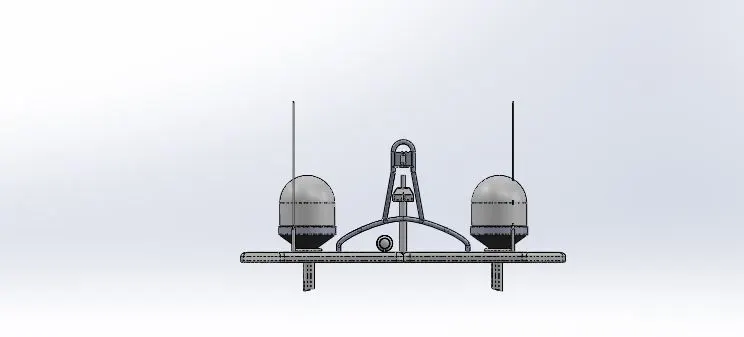
- Radar Mast supporting the ship’s Radar, at the front the containers holding inflatable lifeboats on the side of an ocean, radar and other instruments on the ship.
Assembly Of Yatch :
Assembly of all the Parts which I have explained earlier is fixed to each other using various mates. These mates provide all the parts a constrained motion according to their behavior. The mates which are used in this assembly to combine all the parts are as follows:
Coincident mate – used to give a constrained reciprocating motion to the part
Concentric mate – used to aline the parts in one direction.
Angle mate - used to give a rotary motion to the parts about an axis or plane.
Hinge mate – used to provide the hinge on garage door part.
Tangent mate – used to give a constrained motion to the radar.
Process of Yatch Assembly
- Insert Hull to assembly Environment first.
- Insert Superstructure to assembly environment.
- Insert Propeller to assembly environment.
- Apply concentric and coincident mates to propeller and propeller shaft.
- Insert Garage door in assembly and apply concentric mate to pin and hole of the door.
- Insert Front seat and middle seat respectively, both will automatically locate their position.
- Import Rear seat to the environment and apply coincident with respect to the deck surface with 0 mm as offset distance. Again apply a mate to locate the rear seat 50mm away from a point at the center of the deck surface at the backside exactly above the garage door and a point at the back center of the seat.
- Import Radar Mast to assembly environment it will take its position with respect to superstructure automatically.
- Import Radar to the environment and apply concentric and coincident mate between Radar and Radar Mast.
Conclusion:
Modeling, Assembly, and Photorealistic rendering of the Sunseeker Predator yatch is done successfully by using Solidworks.