Sunseeker Predator Yacht assembly and rendering using Solidworks
Aim:
- To model Radar Mast.
- To assemble all the parts of the Yacht.
- To create a photo-realistic view of assembled Yacht using Solidworks PhotoView360 and Solidworks Visualise.
Theory:
Features used to model the parts:
- Sketch entities: The tools which are used to draw a model in 2D are known as Sketch entities. Line, arc, spline, rectangle, circle, ellipse, slot etc., are known as sketch entities. These are profiles for models. These are drawn on a plane/view.
- Sketch tools: These are used to edit the profiles sketch entities are per requirements. Trim entities, Extend entities, linear patterns, circular patterns, offset entities, move entities etc., are known as Sketch tools.
- Extrude Boss/Base: The profile sketch forcing out to form a 3d model known as Extrude. This can be solid or with a certain thickness. The profile is forced only perpendicular to the plane.
- Swept Boss/Base: The sketch is passed through the curve to form a 3D model in a certain path.
- Revolve Boss/Base: The profile sketch is converted into the model by rotating in certain degrees w.r.t mentioned axis.
- Loft Boss/Base: Multiple profiles are used to create certain 3D shapes where multiple profiles are available at different planes.
- Extrude Cut: The profile is used to cut the modelled material perpendicular to the plane.
- Swept cut: The profile removes the material of a given curve.
- Revolve cut: The profile removes the material to certain degrees.
- Loft cut: The profile removes the material at multiple profiles.
- Fillet: The edges are turned round surfaces by giving radius values.
- Chamfer: The edges of a model are turned into small flat surfaces.
- Linear pattern: The single feature is copied multiple times in a linear direction.
- Circular pattern: The single feature is copied multiple times in a circular direction.
- Dome: The face is selected to form a circular dome or elliptical dome by giving a certain radius.
- Split: After creating the profile, the model is divided.
- Combine: This feature is used to combine different parts into a single body.
- Dynamic mirror: The sketch is automatically mirrored by selecting this option.
- Shell: The solid body is converted into a shell with a certain thickness. Faces can also be selected in this option.
- Appearances: The model appearance should be given with different materialistic appearances or colours. These can be painted, metal, rubber, etc.
- Surface modelling: The above features are also available on surfaces where the profile converted into a thin sheet.
- Surface trim: The unwanted surface is removed by this feature.
- Extend Surface: The surface is extended wherever required.
- Surface knit: Due to the thin sheet metal of the model formed by surface features, gaps are formed between intersections. To fill these gaps, the surface knit option is used.
- Surface extrude: The profile can be extruded as thin sheet metal.
- Swept surface: The profile is converted into a 3D sheet at certain curves.
- Loft surface: The multiple profiles of different planes are converted into a single sheet model.
- Delete face: The surface entire face can be deleted.
Note: Most of the parts in the yacht are modelled in surface features.
Flow chart representing Yacht design steps: In the Yacht model we use both Solid modelling and Surface modelling.

Parts of Sunseeker Predator Yacht assembly:
- Propeller
- Radar
- Hull
- Garage door
- Front Seat
- Middle seat
- Rear seat
- Superstructure
- Radar Mast
Individual part modelling:
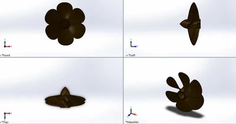
1. Propeller:
Features used:
- Revolve Boss/Base
- Loft
- Extrude cut
- Filter
- Circular pattern
Views of propeller:
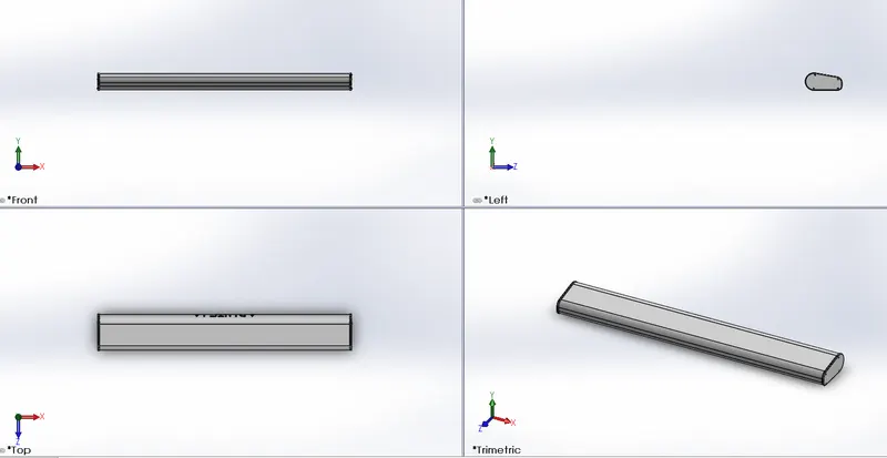
Radar:
Features used:
- Extrude Boss/Base
- Fillet
- Extrude cut
- Split
- Sketch driven pattern
- Mirror
All views of radar:
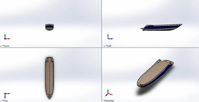
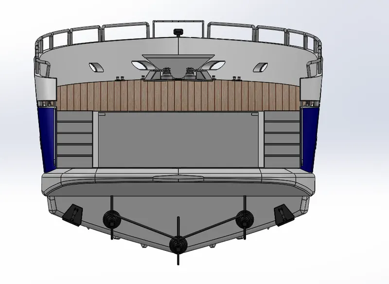
Hull:
Features used:
- Projected curve
- Surface loft
- Surface trim
- Surface extrude
- Knit Surface
- Filled surface
- Shell
- Extrude Boss/Base
- Extrude cut
- Fillet
- Swept Boss/Base
- Chamfer
- Helix and Spiral
- Reference plane
- Linear pattern
- Delete face
- Curve driven pattern
- Combine
- Revolve Boss/Base
- Mirror
- Split
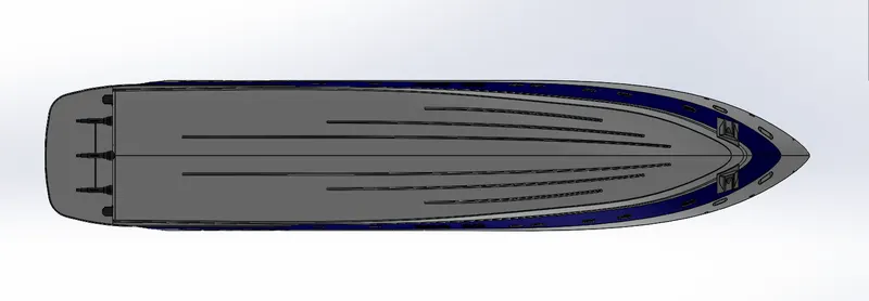
All views of hull:
Garage door:
Features used:
- Shell
- Extrude cut
- Fillet
- Reference plane
- Mirror
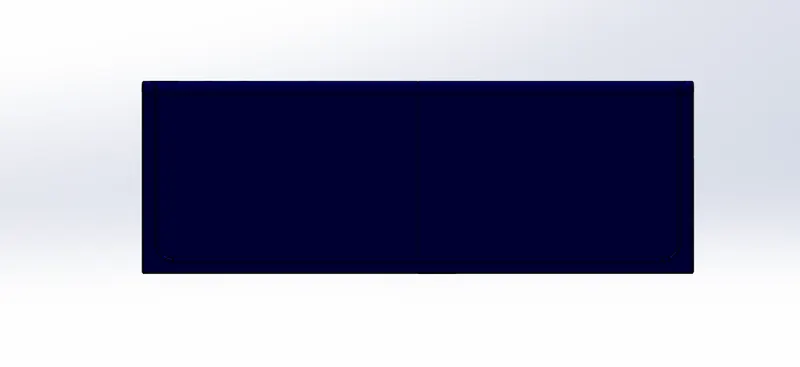
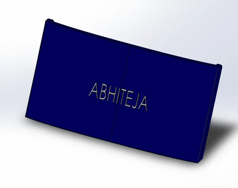
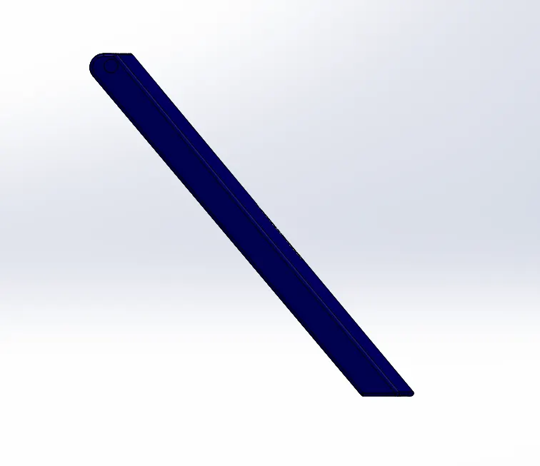
All views of garage door:
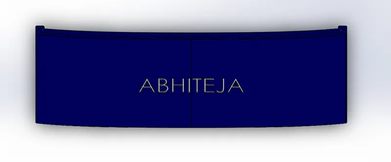
Front seat:
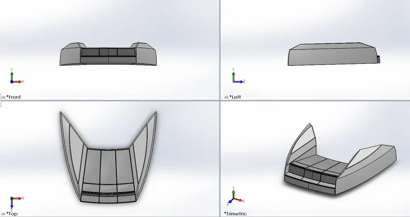
Features used:
- Trim surface
- Surface extrude
- Knit surface
- Filler surface
- Swept surface
- Extrude cut
- Fillet
- Chamfer
- Revolve Boss/Base
- Mirror
All views of front seat:
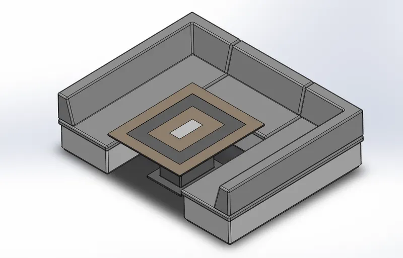
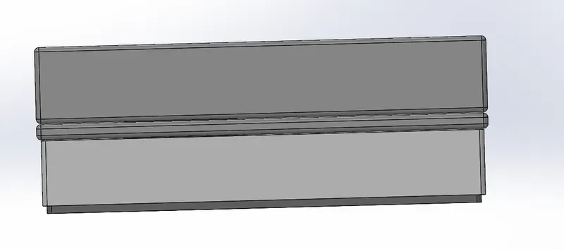
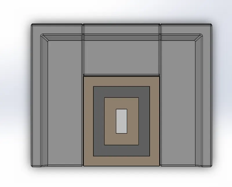
Middle seat:
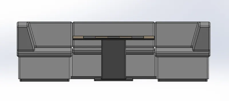
Features used:
- Extrude Boss/Base
- Extrude cut
- Fillet
- Chamfer
- Mirror
- Reference plane
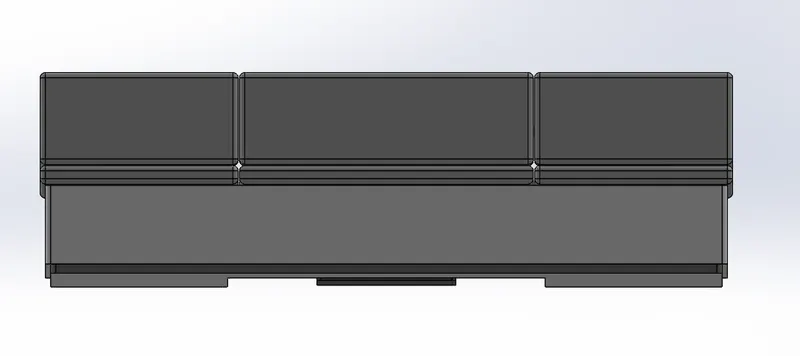
All views of middle seat:
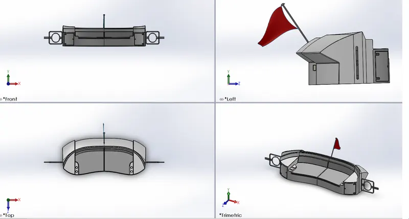
Rear seat:
Features used:
- Extrude Boss/Base
- Fillet
- Revolve Boss/Base
- Dome
- Chamfer
- Linear pattern
All views of rear seat:
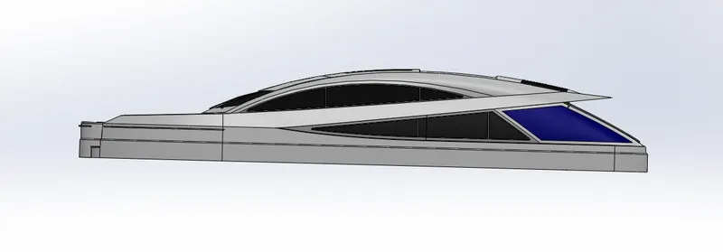
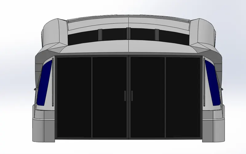
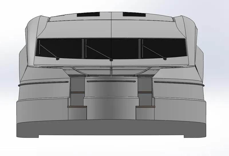
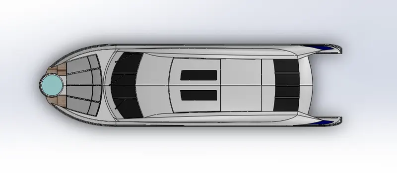
Superstructure:
Features used:
- Projected curve
- Surface loft
- Surface trim
- Surface extrude
- Knit Surface
- Filled surface
- Shell
- Extrude Boss/Base
- Extrude cut
- Fillet
- Swept Boss/Base
- Reference plane
- Linear pattern
- Delete face
- Ruled Surface
- Combine
- Revolve Boss/Base
- Mirror
- Split
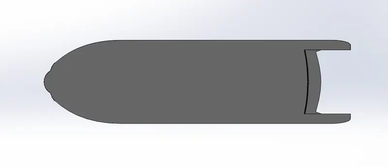
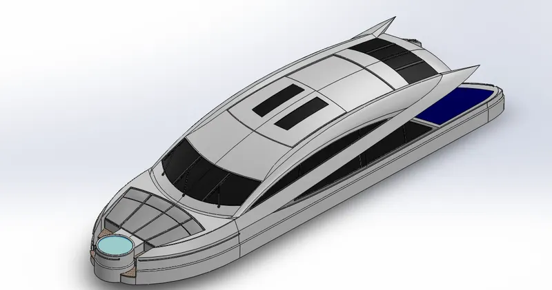
All views of superstructure:
Radar Mast:
Features used:
- Shell
- Revolve Boss/Base
- Dome
- Projected curve
- Trim surface
- Surface extrude
- Extrude Boss/Base
- Swept Boss/Base
- Fillet
- Reference plane
- Mirror
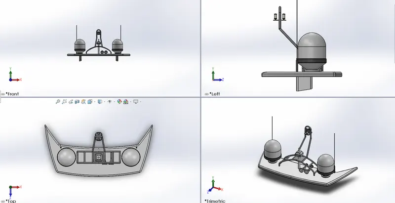
All views of radar mast:
Assembly of Sunseeker Predator Yacht:
Mating relations:
- Concentric: Same profiles of two different models are joined together using this relation.
- Coincident: Face or edges where two of them are joined together using this relation.
- Width: When one model is distant from one another, this relation is used.
- Parallel: It is used to place in parallel relation between any two faces or edges etc.
- Limit angles: Used to rotate the components at certain angles.
Steps followed for assembly:
- Insert all components.
- Drag hull.
- Drag other components one by one.
- Apply mating relations with the hull.
- Apply mating relations by coincident relation with planes.
All views of Sunseeker Predator Yacht Assembly:
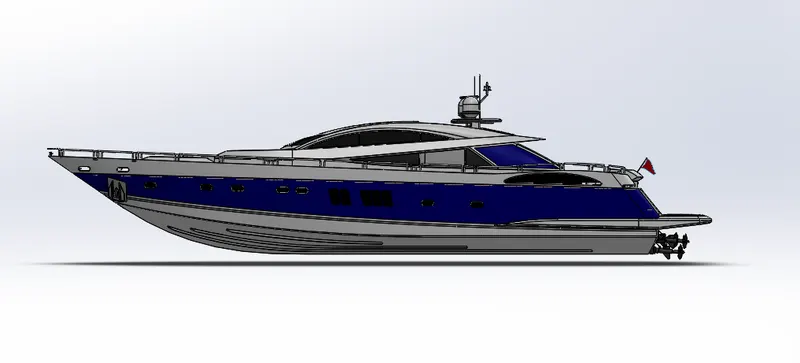
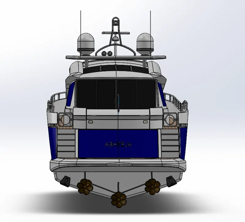
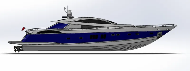
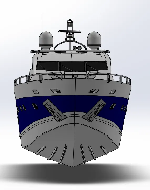
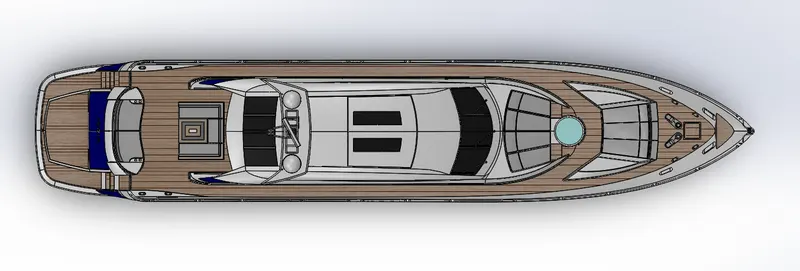
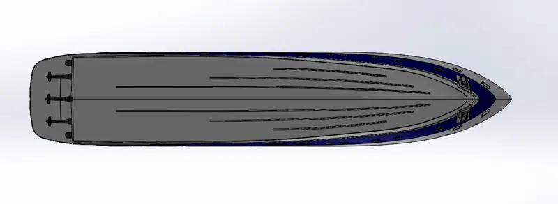
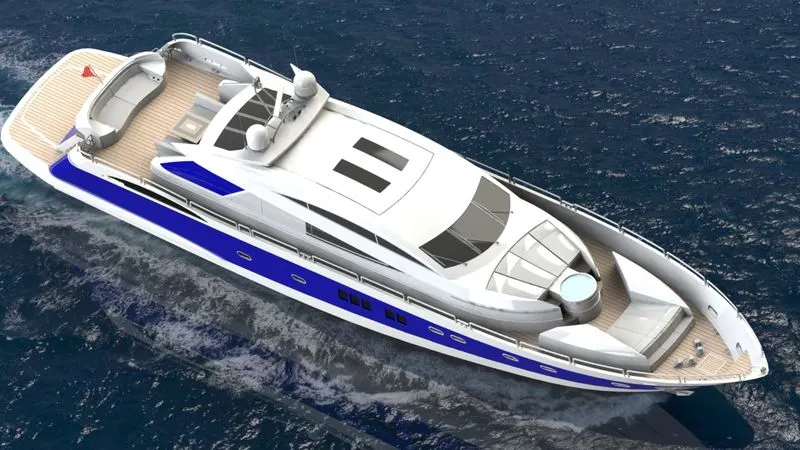
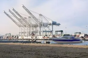
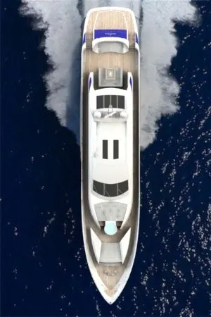
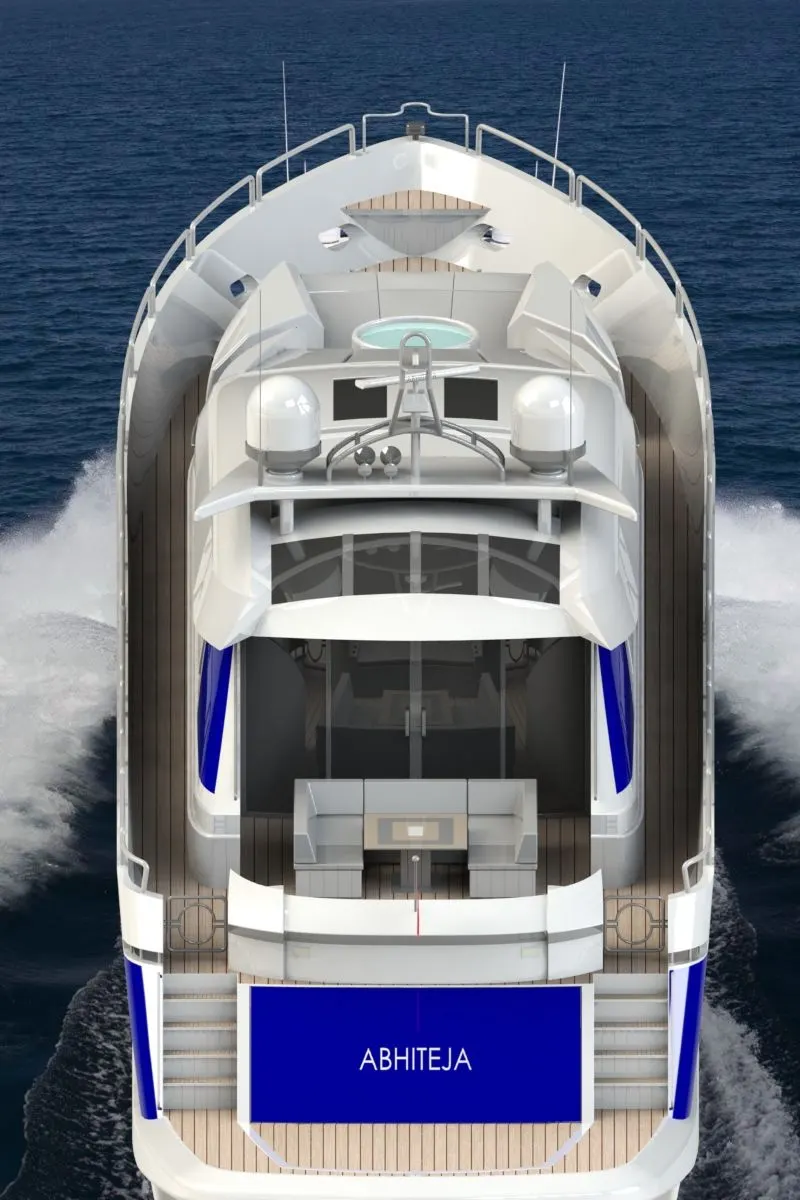
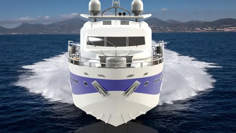
Rendering: The Yacht assembly is rendered using Solidworks Photo360. All views of a yacht are rendered as shown below.
Points to remember:
- Always the sketch should be fully defined.
- The sizes of individual models should be checked for avoiding differences in assembly.
- The mating relations should be given correctly in assembly.
- The appearances in realistic view should be more efficient than the model designed.
- Camera, size and lightning adjustments need to be done carefully while rendering.
- Plane and view notations of individual components should match with assembly.
CAD models: Sunseeker Predator Yacht assembly and parts
Conclusion: Sunseeker Predator Yacht individual parts modelled and assembled using Solidworks. Rendering is done using Solidworks PhotoView360 and Solidworks Visualise.