Radar Mast & Final Assembly of Yacht
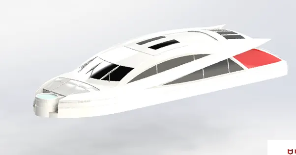
Design ,Assembly and photo realistic rendering of an yacht:
Objective:
The object of the project is to design and model parts of yacht and assembling it to create the photo realistic rendering of the yacht.
Introduction:
In the project the yacht was taken as a conceptual model, to understand the methodology of the model solid modeling and surface modeling .each every part of the yacht design and model by suing solid works were assembly by adding proper mates and constraints to create the photo-realistic render image of yacht.
Design process;
- Define the problem
- Collect the information
- Brainstorm and analyze ideas
- Develop solutions
- Gather feedback
- Improve the design.
Design requirements:
Design requirements as to follow :
- Product must optimally perform its main function.
- It must be easy to repair at the low cost repair.
- It must easy to use
- Follow principles of aesthetics.
- It must be durable one
- It can be easily produced in large numbers at minimum production cost.
- Simple to produce and handle.
- It must also ne compact.
Design intent:
In this project, we can able to sketch and build the entire yacht by using the solid works to understand the 3d modeling.
In this project we well learn like ,curve generation ,surface creation from the curve and sketch, different type of surface there lofted surface ,rule surface fill surface ,copy and move surface ,surface knit , ,mirror surface.
- Blue print setup
- Modeling of propeller and radar
- Modeling of middle seat and front seat ,rear seat.
- Modeling of garage door ,hull
- Creating the superstructure.
- Finally assembly of yach
Design approach:
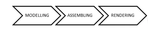
Design methodology:
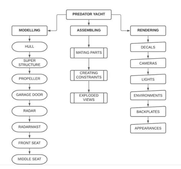
Terminology:
These terms appear though out the solid works software and documentation.
Origin: appears as two blue arrows and representation the (0,0,0) coordinate of the model. When a sketch is active , a sketch origin appears in red and represents the (0,0,0) coordination of the sketch dimensions and relations can be added to model origin but not to sketch origin.
Plane : flat construction geometry ,planes can be used for 2D sketch
Axis: straight line used to create the model geometry , feature or patterns.
Face : boundaries that help define the shape of a model or surface.
Edges : location where two or more faces intersect are joined together.
Vertex: point at which two or more line are edges intersect.
Part model description:
Blue print :
A blueprint is a guide for making something it's a design or pattern that can be followed. ... The literal meaning of a blueprint is a paper which is blue with plans for a building printed on it. You can also call other guides or plans blueprints.
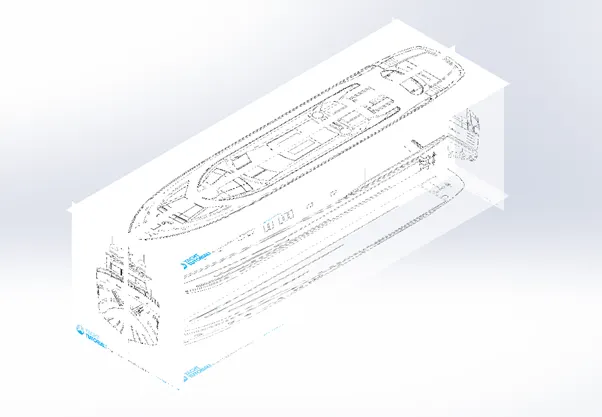
The above shown blue print was used to make the yacht in fully constraints.
Place the blue print in different planes.
They were easy to read and fast to make .
Hull :
A hull is the watertight body of a ship, boat, or flying boat. The hull may open at the top (such as a dinghy), or it may be fully or partially covered with a deck. ... The line where the hull meets the water surface is called the waterline.
Command used :
In sketch:
- Line
- Circle
- Rectangle
- Arc
- Slot
- 3-D sketch
- Sketch picture .
In surface :
- Surface fill.
- Surface trim
- Extrude surface
- Revolve surface
- Loft surface
- Delect face
- Surface knite
In feature:
- Project cure
- Reference Plane
- Chamfer
- Fillet
- Split
- Split line
- Extrude boss base
- Extruded cut
- Mirror
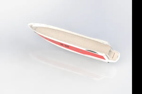
Super structure:
The definition of a superstructure is a building or part of a building built above the foundation. An example of a superstructure is the lobby and floors in a high rise building. The parts of a ship's structure above the main deck.
Command used :
In sketch:
- Sketch picture
- 3D Sketch
- Line
- Circle
- Rectangle
- Center point angle
In surface :
- Surface fill.
- Surface trim
- Extrude surface
- Revolve surface
- Loft surface
- Rule surface
- Extend surface
- Surface kinte
- Fillet
- Chamfer
In feature:
- Project curve
- Reference curve
- Split line
- Split
- Convert entities
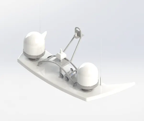
Radar:
Radars are now used to help navigate ships in fog and airplanes in bad weather. Radar can detect a speeding car and track a satellite. Most importantly for meteorologists, radars can detect all sorts of atmospheric phenomena.
In sketch :
- Line
- Text
- Point
- Circle
In feature:
- Extrude boss/base
- Extruded cut
- Sketch pattern
- Fillet
- Mirror
- Split line
Radar mast:
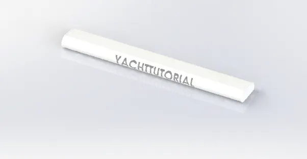
Each unit has a waterproof radar cable gland positioned aft and below the top plate. ... Unlike our Power Mount Plus these Standard Mounts are not Light/GPS Bar capable.
All radar works by emitting a high frequency radio wave, and then listening for any return signals that get bounced back. ... But radar waves aren't just bounced back by boats and channel markers. Rain, flocks of birds, or even rough seas can reflect enough radar waves to confuse the unit and the unit's user.
In sketch :
- Sketch picture
- Line
- Spline’
- Rectangle
- Arcs
In feature:
- Extrude boss/base
- Loft
- Revolve
- Swept
- Project curve
- Reference plane
- Fillet
- Mirror
- Demo
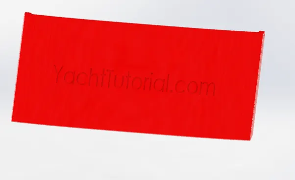
Garage door:
Companionway doors take their name from the companionway of a sailboat, which is the access to a sailboat's cabin space.
cruise vessels and yachts are currently equipped with our sliding watertight doors and splashtight doors. Our Products: Watertight Sliding Doors Watertight ...
In sketch:
- Line
- Spline
- Circle
- Text
In feature:
- Extrude cut
- Reference plane
- Fillet
- Shell
- Mirror
Front seat:
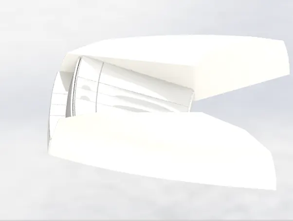
Front seats feature two connect seats that are built back to back from one and other.
They have a built-in storage unit underneath them it is easier for you to kick your feet up and more comfortable. sun pads are great way to reclaim lost space on our boat
In sketch:
- Sketch picture
- Line
- Spline
- Circle
- Arc
In facture:
- Extrude cut
- Revolve boss/base
- Chamfer
- Fillet
- Mirror
- Demo
In surface:
- Extrude surface
- Surface trim
- Knit surface
- Swept surface
- Loft surface
- Revolve surface
Middle seat:
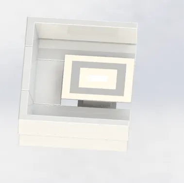
The middle seat is placed behind the superstructure.it is provided with a luxury table to dine out.
In sketch:
- Sketch picture
- Line
In facture:
- Extrude cut
- Chamfer
- Fillet
- Mirror
- Extrude Bose/base
Rear seat:
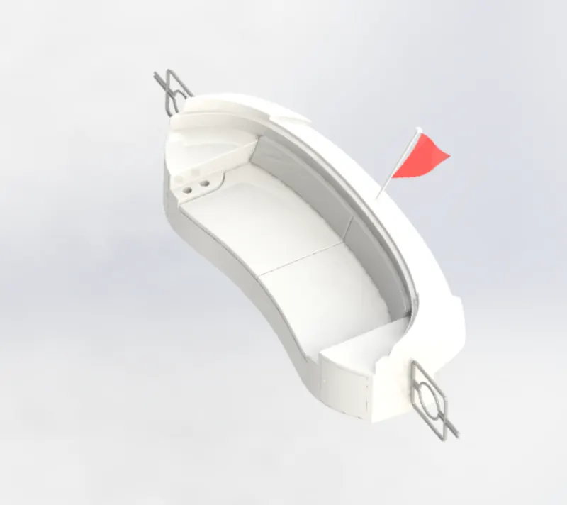
Rear seat placed at the end of the deck surface. The rear seat consist of locker racks and steel doors for our stairs. Flag also placed to rear seat.
In sketch :
- Sketch picture
- Line
- Circle
- Spline
- Rectangle
- Arc
In surface:
- Swept surface
- Extrude surface
- Offset surface
- Filled surface
- Knit surface
- Ruled surface
- Loft surface
In feature:
- Reference plane
- Extrude Bose/base
- Revolve bose/base
- Fillet
- Mirror
Assembly:
Assembly is document in which parts features, and other assemblies are mate together .
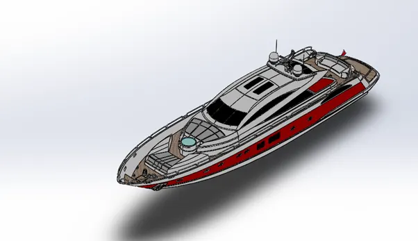
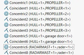
Commands are used :
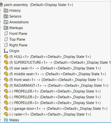
: Tree structure of assembly
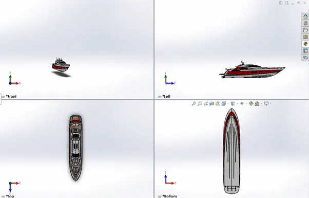
Front ,side ,top ,isometric view :
Rendering:
Render tools command:
Render tools command is used to adjust the decals and appearance on the model.
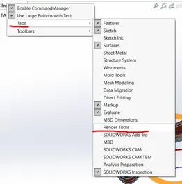
Render tool is in tool bar, if in case you not find tool in the tool bar.
We have to customize tool or select the any command in the tool click the right click of the mouse and go to tabs and active the render tool shows in the figure.
You can activate accounting to your requirement.
Activate and de-activate command in tabs
How to activate the photo 360?
Go to search bar and type add in
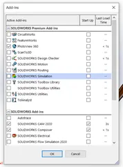
Select the photo 360.

Tools are activated, if not activate the photo 360 this tool are also not activated.
Decal: select the gas tank and open in part body.
Final render:
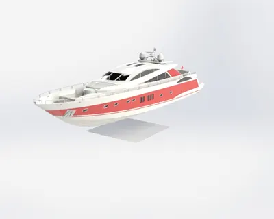
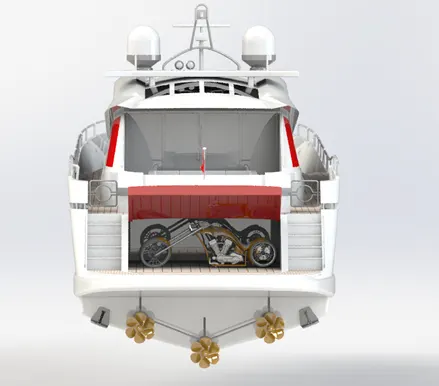
Photo visualize:
Select the file and go import and select all file .
Then assembly will project on the screen.
There are multiple option they are show in the figure.
Environment is used adjust the background.
Select the appearance
Select th e paints
Drag anddrop on the required parts
I have used purple print.
You change by drag and drop method.
Add camera they are options.
Adjust the camera by using the tools.
It as to look as possible as natural play with tools .
If you bike is in perfect position then do the rendering
Download the background and add it.
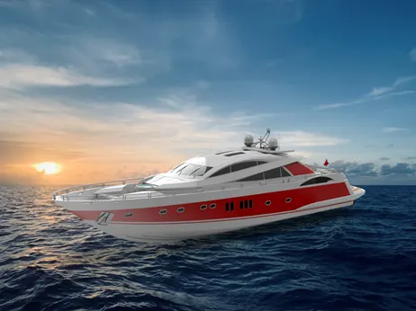
Final out put of the photo visualize.