Advanced Sheet Metal Design Using NX Cad Challenge_6_Bracket
Design of Bracket from 2D Using NX Sheet Metal.
1. Objective: In this project, the main objection is to create the metal bracket from a 2d drawing as per the given dimensions Using the Siemens NX Sheet metal application.
2. Introduction: During this creation process, we are learning and using different types of tools and features available in the CAD application. This application has a lot of basic and advanced features such as Tab, flange, break corner, normal cut out, dimples, etc. The tool's flat pattern gives the manufacturer an idea about the material requirements positions of bends, and holes and helps in the designing of the manufacturing process.
3. Design Methodology:
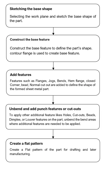
4. Description of the design process:
Step 1: Open the new file → select the sheet metal default template → select the datum coordinates → start the sketching as per the given dimensions.
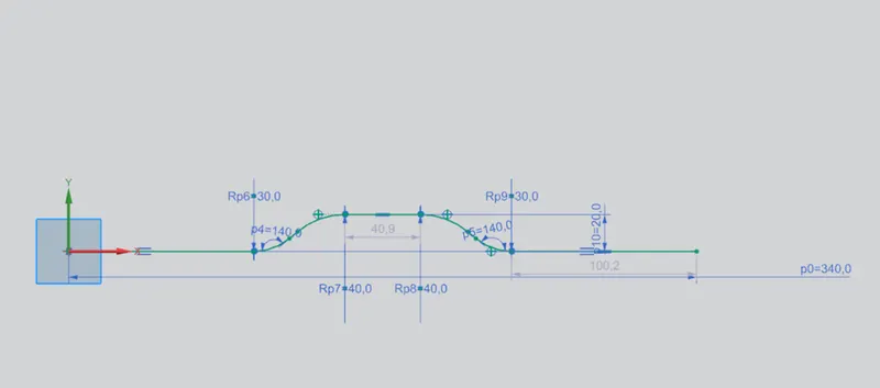
Basic Sketch.
Step 2: Select the contour flange → select the curves of the sketch → specifying the thickness of the sheet metal and width of the sheet in the contour flange.
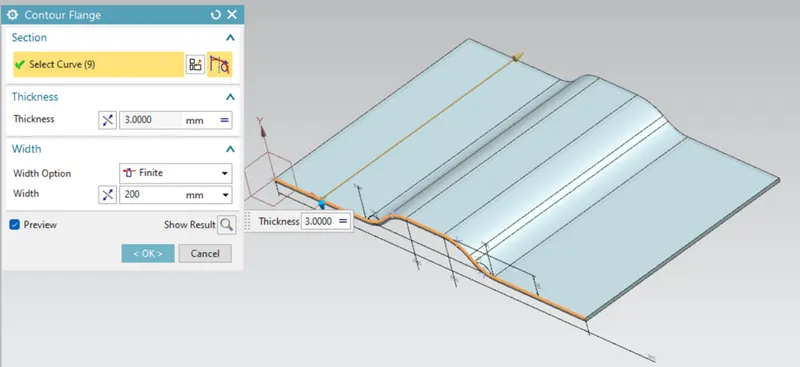
Contour Flange.
Step 3: To create the normal cut out → Design a sketch on the top surface of the created sheet metal → Select the Normal cut out and enter the thought depth.
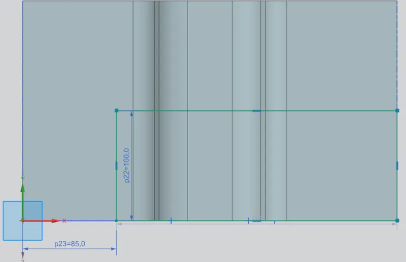
Sketch for the normal cut-out.
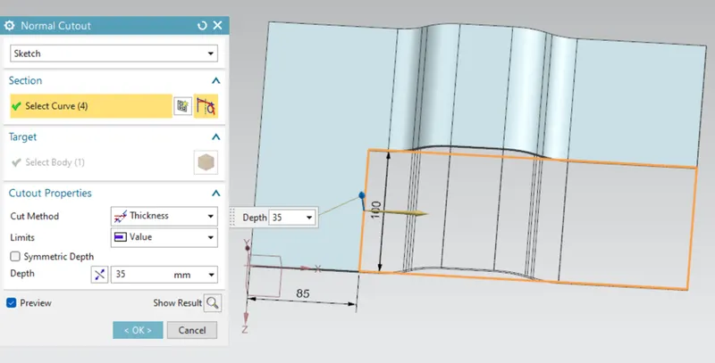
Normal cut-out.
Step 4: To design rounding the corners → select the break corner feature → Select the respective edges and enter the radius of the corners → repeat the sequence of steps, and apply the break corner to all the respective corners with respective radius.
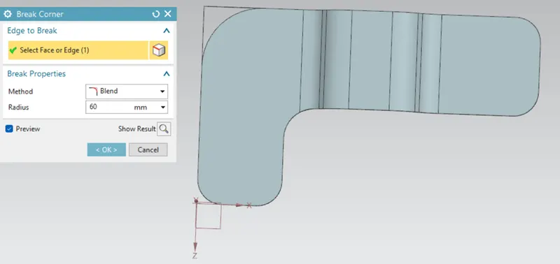
Break corner.
Step 5: To create the Bead → first create a line with given dimensions → unbend the sheet to flat → apply the bead as per the given dimensions → apply the rebend to bring it to the original shape of the design.
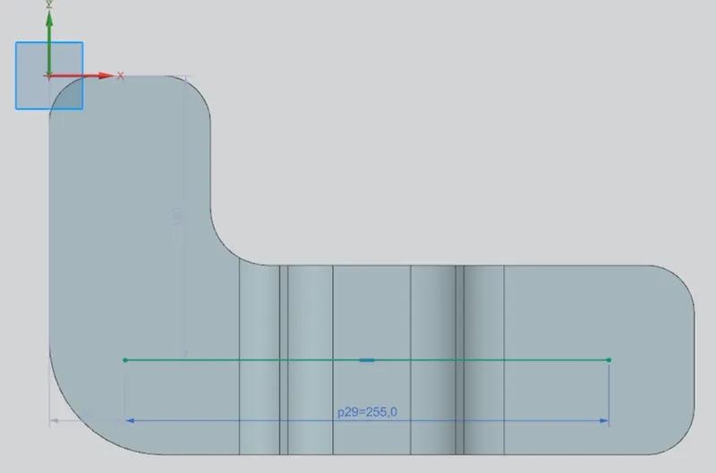
Sketch for a bead.
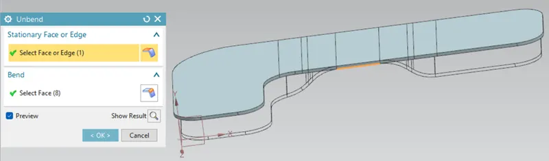
Unbend.
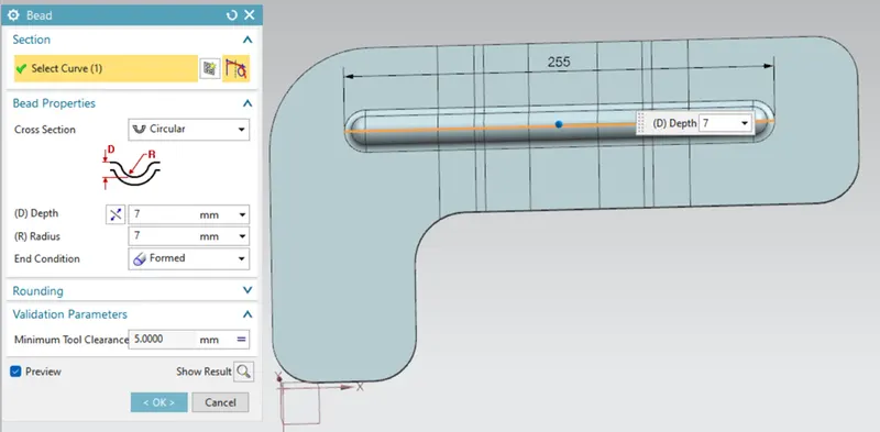
Bead.
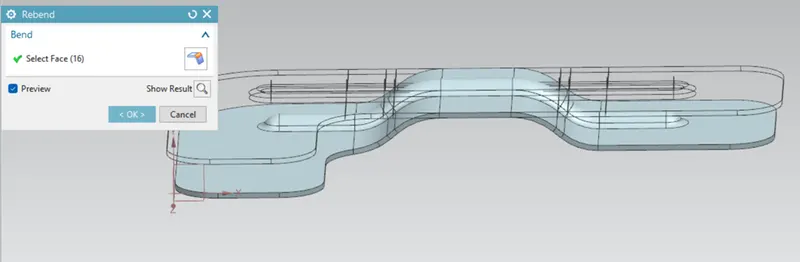
Rebend.
Step 6: To add all the feature designs to the sheet metal → the final feature of holes is added at the required locations. Select the hole feature → select the locations on the sheet to create the holes.
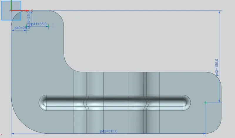
Sketch the location of the holes.
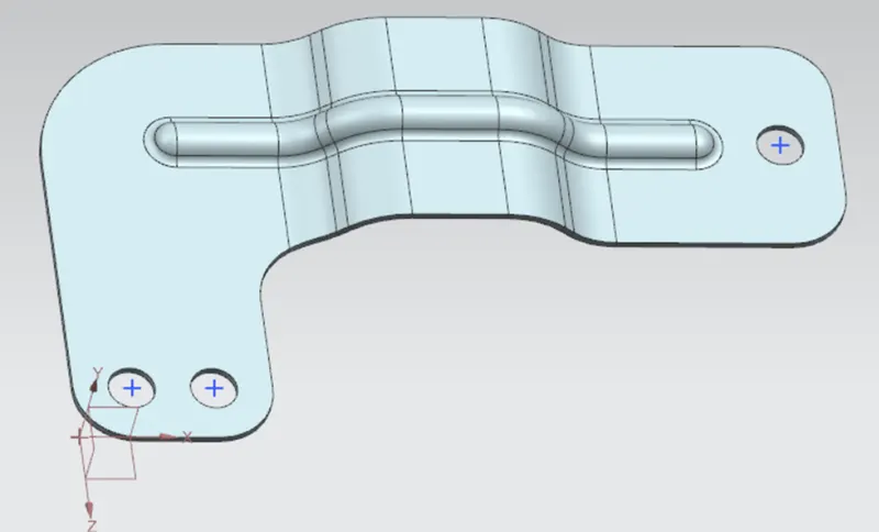
Holes.
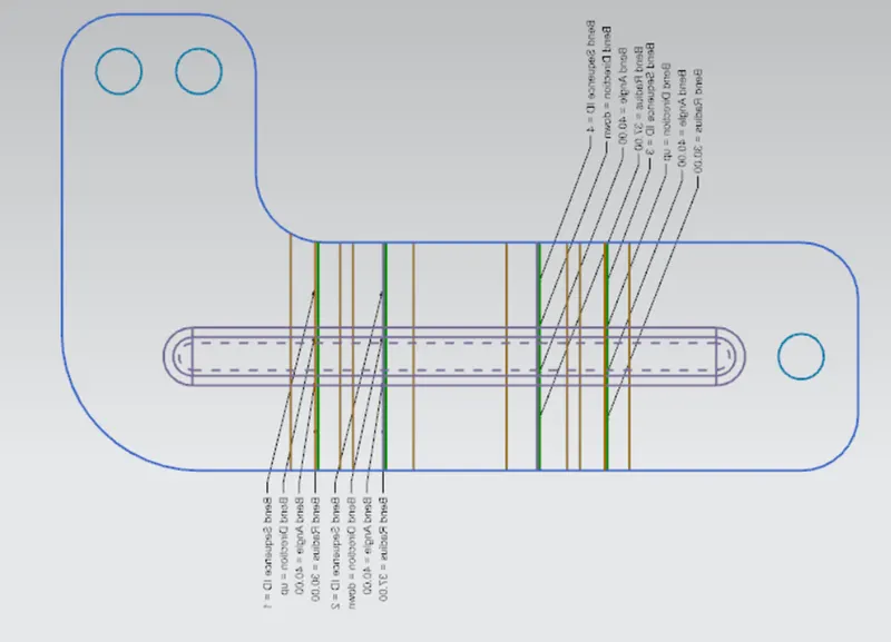
Flat pattern.
Drawing Sheet:
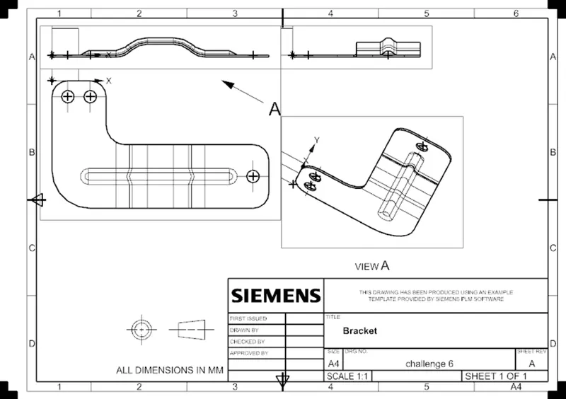
Drawing sheet.
Views:
Isometric view:
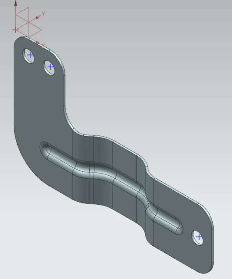
Isometric View.
Top view:
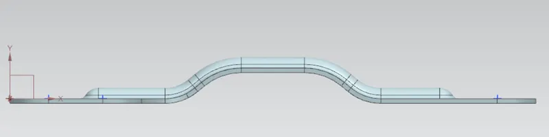
Top view.
Front View:
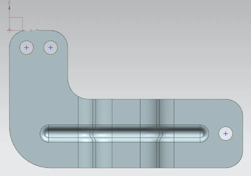
Front View.
Side View:
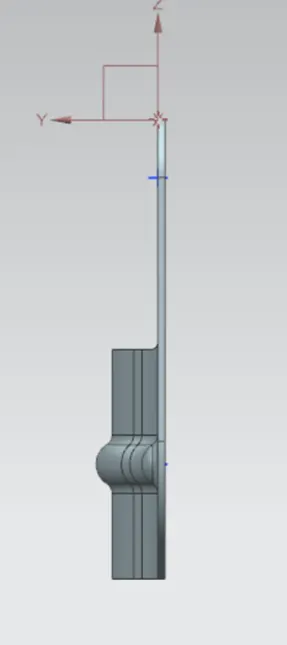
Side View.
Conclusion: The design of the bracket along with the views was achieved by using the above sequences of steps and features.