Radar Mast & Final Assembly of Yacht
SANDEEP_RADARMAST
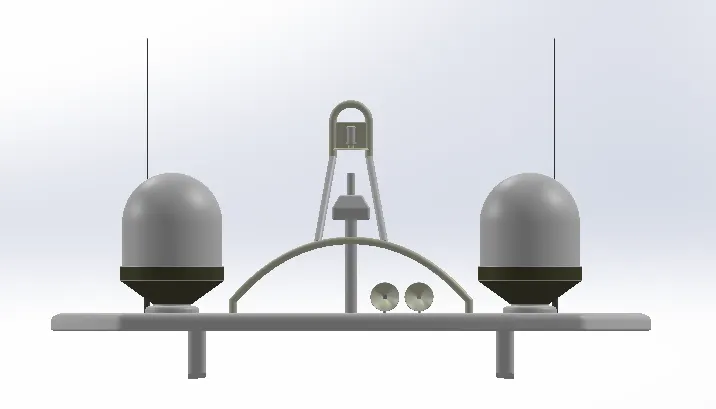
RADARMAST_FRONTVIEW
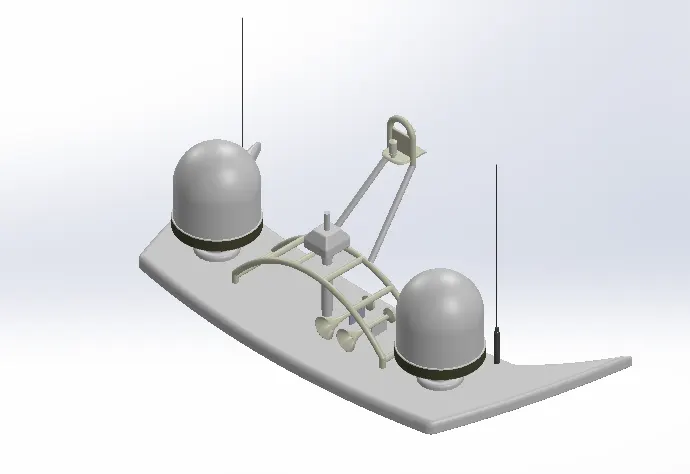
RADARMAST_ISOVIEW
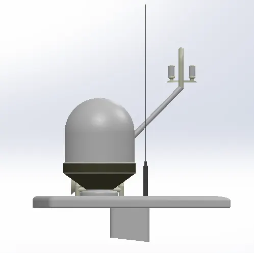
RADARMAST_SIDEVIEW
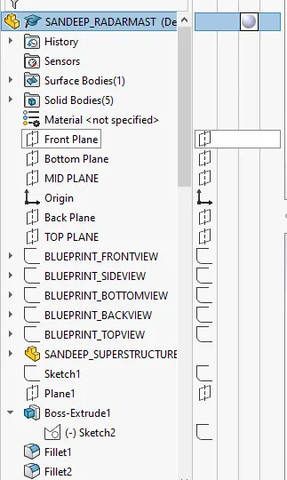
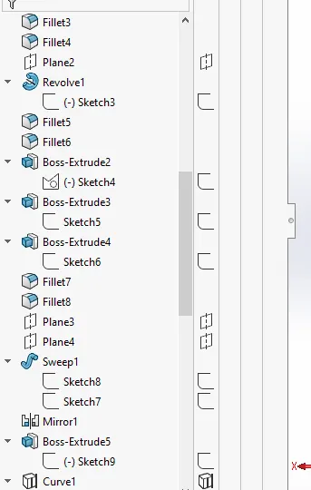
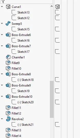
RADARMAST FEATURE TREE
SANDEEP_YACHT ASSEMBLY
ASSEMBLY ISOVIEW
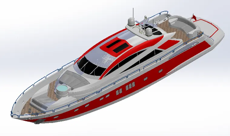
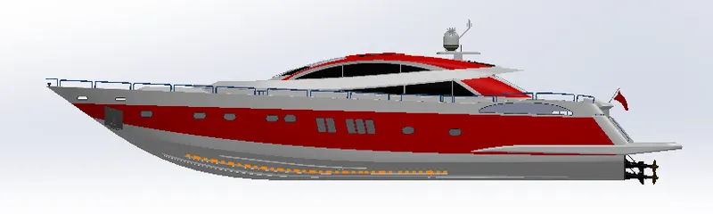
ASSEMBLY_SIDEVIEW
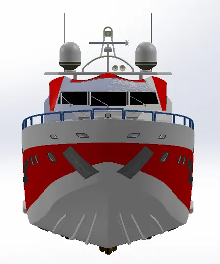
ASSEMBLY_FRONTVIEW
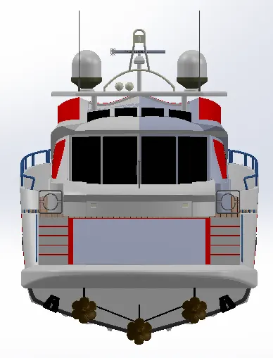
ASSEMBLY_BACKVIEW
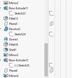
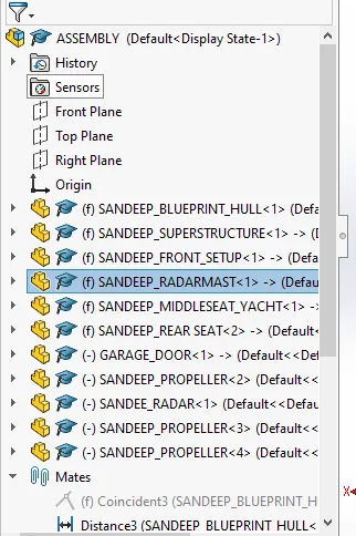
FEATURE TREE
FINAL ASSEMBLY/MODELLING SUNSEEKER PREDATOR YACHT REPORT
TITLE OF THE PROJECT:
MODELLING SUNSEEKER PREDATOR YACHT
OBJECTIVE:
- To design individual parts of the yacht with fully defined sketches and appropriate appearances.
- To assemble all the individual parts of the yacht model by assigning suitable constraints.
- To render the yacht model by adding appearances, decals, lights, cameras and background scenes.
SOFTWARE’S USED:
- Solid-works 2021
- Solid-works Visualize 2021
INTRODUCTION:
The Solidworks is a CAD software which is a mechanical design automation application that lets designer quickly sketch out ideas, experiment and feature & dimension , and produce model and detailed drawing this software is mainly using 2D sketch.
Parts are basic building blocks in the solidworks software . Assemblies contain parts or other assemblies called subassemblies. Solidworks model consists of 3D geometery that define edge face and surface. The solidwork software lets us design models quickly and precisely. It has other ADD-in feature like photoview360which helpin rendering of final models to make it look photorealistic.
YACHT:
A yacht sailing or power vessel used for pleasure, cruising, or racing.There is no standard definition, so the term applies to such vessels that have a cabin with amenities that accommodate overnight use. To be termed a yacht, as opposed to a boat, such a pleasure vessel is likely to be at least 33 feet (10 m) in length and may have been judged to have good aesthetic qualities.The Commercial Yacht Code classifies yachts 79 ft (24 m) and over as large.
The term, yacht, originates from the DUTCH word and originally referred to light, fast sailing vessels that the dutch republic navy used to pursue pirates and other transgressors around and into the shallow waters of the low country.
DESIGN METHODOLOGY/APPROACH:
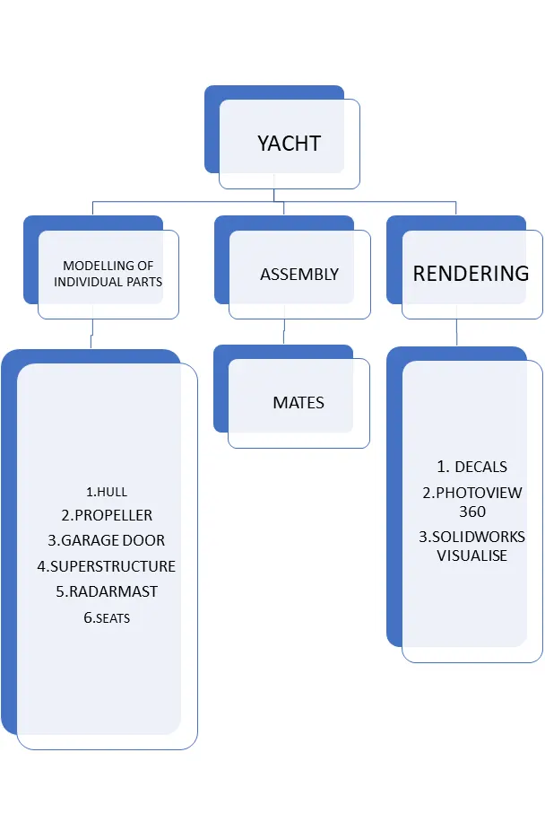
DESIGN PROCESS:
THE Entire modelling process is divided into 6 stage:
- Blue Print Set up & Creating Planes.
- Modelling Of Hull Part.
- Modelling Of Super Structure.
- Modeeling Of Radar Mast.
- Modelling of front, middle & Rear seats.
- Assembling the individual parts.
PARTS OF YACHT:
- PROPELLER
- RADAR
- BLUEPRINT
- HULL
- MIDDLE SEAT
- FRONT SEAT
- REAR SEAT
- GARAGE DOOR
- SUPERSTRUCTURE
- RADARMAST
PROPELLER:
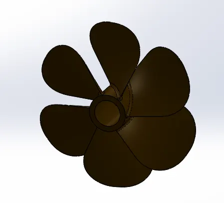
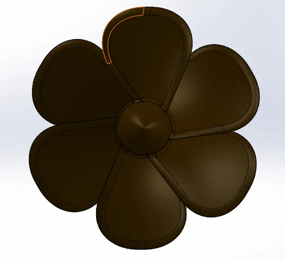
A Propelleris a device with a rotating hub and radiating blades that are set a pitch to form a helical spiral, that when rotated, performs an action which is similar to archimedes screw . It transforms rotational power into liner thrust by acting upon a working fluid, such as water or air. the rotational motion of the blades is converted into thrust by creating a pressure difference b/w the surfaces. a given mass of working fluid is accelerated in one direction and the craft moves in the opposite direction. Propeller dynamics, like thos eof aircraft wings, can be modelled by bernoulli's principle and newton's thied law . Most marine propellers are screw propellers with helics blades rotating on a propeller shaft with an approx horizontal axis . The Sketch profile are created with provided dimensions and the feature applied.
Features used to create propeller.
- sketch
- Loft
- Revolve
- circular pattern
- Fillet
- Extrude cut
SKETCH:- A Sketch is a 2D profile or cross section. to create 2D sketch, we use a plane or a planer face .It is a 2d representation of the model sketch of any model can be creates by using various commands such as line, circle ,spline arc etc .
LOFT EXTRUDE:- Surface generated by existing edges creating a smooth tangent b/w the selected curves.
REVOLVE/BOSS:- This feature helps to revolve the open sketch as well as closed sketch with the help of one axis.
CIRCULAR PATTERN:- For this feature one selection of face is required and selections of equal spacing with required angle and number of instances,
FILLET: Fillets are used to create a smooth curve on the profile or at the edge . For this constant size , fillet is used.
EXTRUDE CUT: This is used to remove the material from the solid model with the required depth or draft.
RADAR
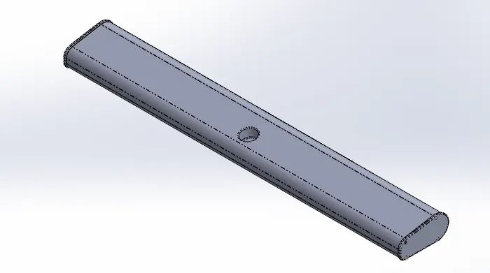
- EXTRUDE BOSS/BASS
- FILLET
- EXTRUDE CUT
- SKETCH PATTERN
- MIRROR
- EXTRUDE BOSS/BASS :- Extrude a sketchor selected sketch contours in one or two direction to create solid feature.
- EXTRUDE CUT :- Cuts a solid model by extruding a sketched profile in one or two direction. If the cut offset multiple bodies in multibody part , we can select which bodies to keep in the bodies to keep dialog box.
- SKETCH PATTERN :- In this feature selection of face is required to create multiple faces by selecting 2D sketches.
- MIRROR :- Mirror is used with midplane or midline through which it is similarly and symmetrically with the original body which is mirror.
BLUEPRINT
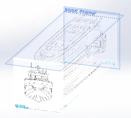
Blueprint is basically a design plan or technical drawings of different orthographics views of a product. The main motto of the blueprint is to bring out the excat same shape and from of the product as designed by a designer. It also the accuracy and the proportion of the product. Designing a product without a blueprint may lead to multiple errors, unnatural proportions and improper dimensions. A proper blueprint setup omits all those problems. To set up a blueprint, we use sketch mode in SOLIDWORKS in each plane. In this case, the image provided for the front view , side view, top view ,back view are added in respective planes. One very important thing to note while setting up a blueprint is the size of it. All the parts are going to be designed laying up the blueprint and taking its reference , it is very crucial to maintain the correct and real size of the blueprint in the very first step. It can either be adjusted manually with the dimensions or by adjusting the scale bar.
HULL
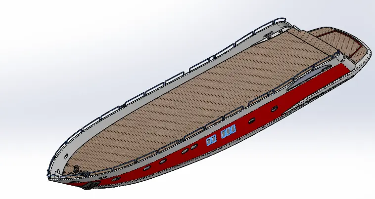
FEATURE USED
- PROJECTED CURVE
- SURFACE LOFT
- SURFACE TRIM
- SURFACE EXTRUDE
- KNIT SURFACE
- SURFACE FILL
- SHELL
- EXTRUDE CUT
- EXTRUDE BOSS/BASS
- FILLET
- MIRROR
PROJECTED CURVE:- This sketch is used as a 3D curve on the profile . This curve cab be achieved by two different line or spline which starts from same direction and ends in the same direction with two different planes.
SURFACE LOFT:- This will not create any solid body it creates only 0 thickness profile by selecting the line or spline as profile and guide curve.
SURFACE TRIM:- Feature is applicable for surface modelling only not for solid modelling .It trim on surface with the help of sketch entities only.
SURFACE EXTRUDE:- With an open sketch also the surface extrude can be done , it need not be a close sketch. Again this feature works with surface modelling only.
KNIT SURFACE:- Knit is used to reduce the gap b/w the two surfaces.
SURFACE FILL:- surface fill is similar to surface loft.
SHELL:- Shell is used to create a hollow profile by selecting the face or body with required thickness.
MIDDLE SEAT
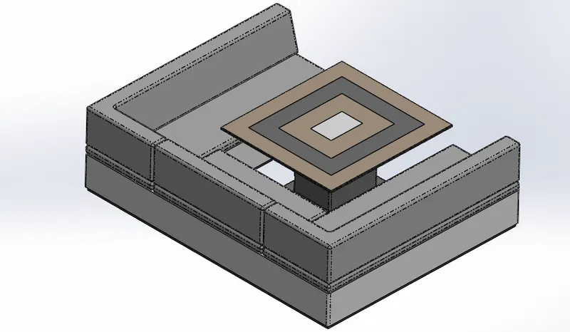
FEATURE USED
- SKETCH
- EXTRUDE BOSS/BASS
- FILLET/CHAMFER
- MIRROR
- EXTRUDE CUT
- DOME
DOME:- This command used to give some convex shape to selected surface.
FRONT SEAT
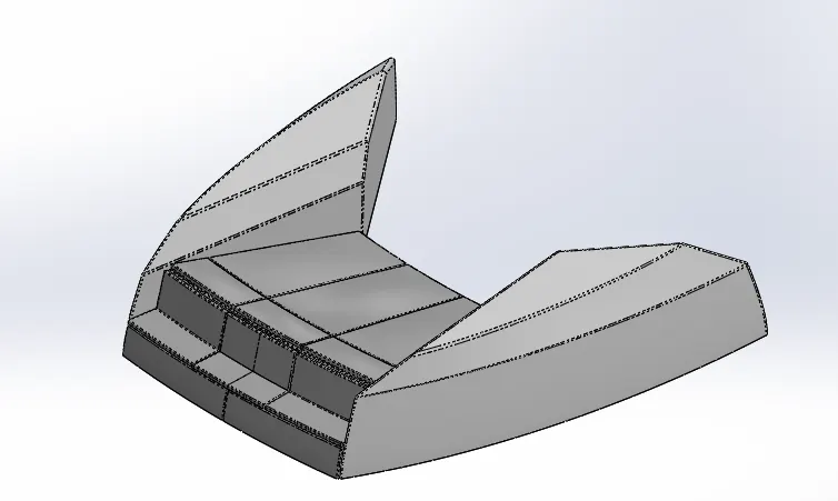
FEATURE USED
- SKETCH
- PLANE
- SURFACE LOFT
- SURFACE TRIM
- EXTRUDE CUT
- REVOLVE
- SURFACE KNIT
- SURFACE FILL
- DOME
- FILLET
- CHAMFER
REAR SEAT
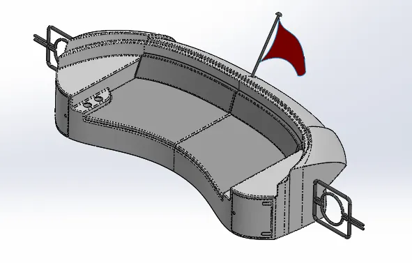
FEATURE USED
- SURFACE LOFT
- SURFACE EXTRUDE
- SURFACE OFFSET
- SURFACE TRIM
- SWEEP
- RULED SURFACE
- SURFACE EXTEND
- SURFACE KNIT
- SURFACE EXTEND
- EXTRUDE BOSE
- CHAMFER
- EXTRUDE CUT
- MIRROR
- PLANE
- FILLET
GARAGE DOOR
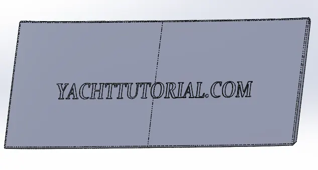
FEATURE USED
- EXTRUDE CUT
- MIRROR
- TEXT
- FILLET
- SHELL
- PLANE
SUPERSTRUCTURE
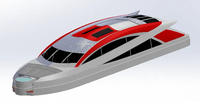
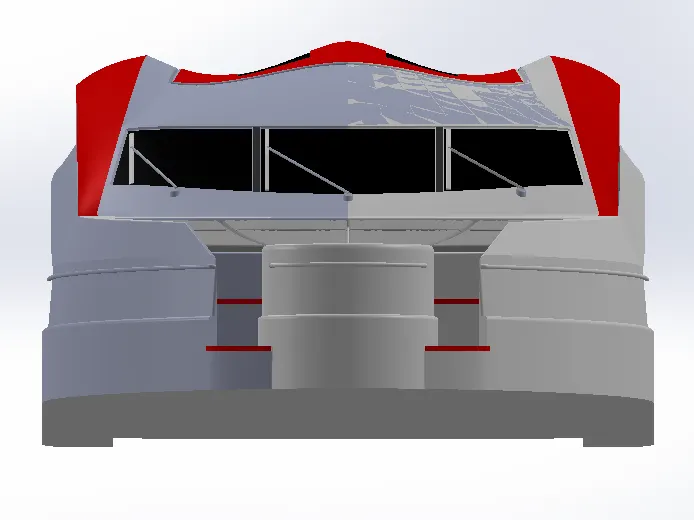
FEATUFRE USED
- SKETCH
- SPLINE
- EXTRUDE CUT
- PROJECTED CURVES
- OFFSET
- SURFACE FILL
- SURFACE EXTRUDE
- SURFACE SWEEP
- DOME
- SURFACE TRIM
- EXTEND SURFACE
- SURFACE KNIT
- PLANE
- RULED SURFACES
- SPLIT ENTITIES
- SPLIT LINES
- DELETE LINES
- FILLET
- CHAMFER
- MIRROR
SURFACE SWEEP:- It is the same as sweep boss but in surface modelling surface sweep is used by selecting profile and the part for the sweep.
RULED SURFACE:- Ruled surface creates a tapered curves surface with the help of a single edge with a specified distance.
RADARMAST
FEATURE USED
- EXTRUDE BOSS/BASE
- FILLET
- SURFACE SWEEP
- DOME
- REVOLVE/BOSS
- MIRROR
- SHELL
ASSEMBLY
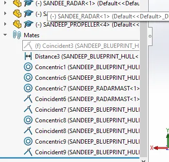
The assemblyof the yacht is quit simple since we have taken the base deck surface for the most of the parts it gets mated automatically although some mates are used to assemble the yacht.
MATES USED
- Coincident
- concentric
- Distance
ASSEMBLY ISO VIEW
ASSEMBLY SIDE VIEW
ASSEMBLY FRONT VIEW
ASSEMBLY BACK VIEW
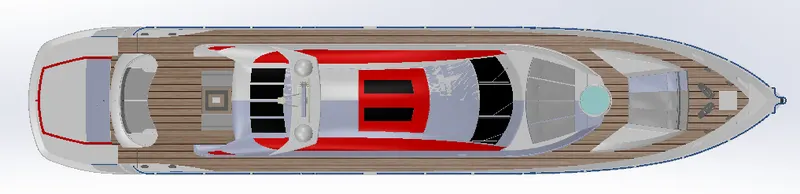
ASSEMBLY TOPVIEW
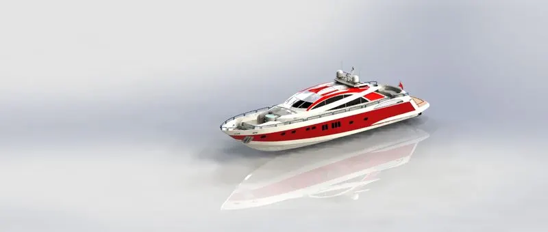
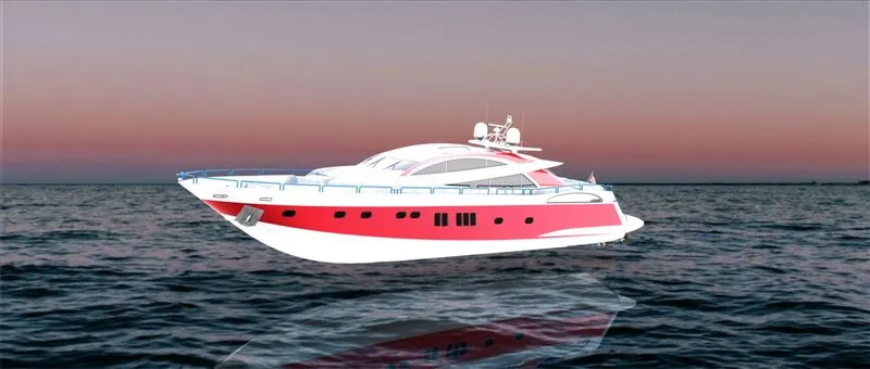
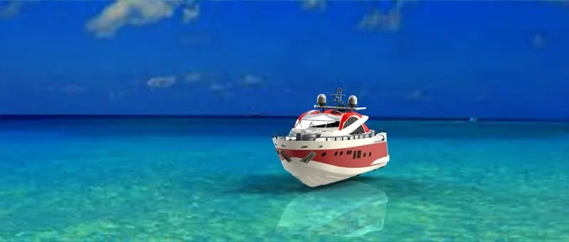
FINAL RENDERING
CONCLUSION
To conclude, design assembly and rendering of the sunseeker predator yacht are done using SOLIDWORKS.