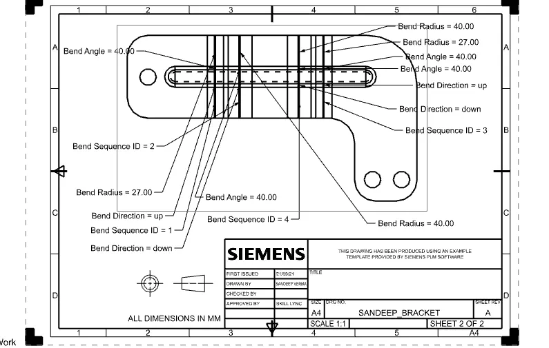
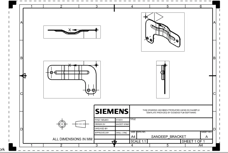
Advanced Sheet Metal Design Using NX Cad Challenge_6_Bracket
TITLE OF THE PROJECT
BRACKET
OBJECTIVE
The objective of this design is to create BRACKET with the help of NX advance sheet metal.
INTRODUCTION
Sheet metal is metal formed by an industrial process into thin, flat pieces. Sheet metal is one of the fundamental forms used in metal working, and it can be cut and bend into a variety of shapes. sheet metal is a semi- finished product that can be produced over a large area, whereby sheets are generally light, thin, stable, elastic and flat.
DESIGN APPROACH METHOD
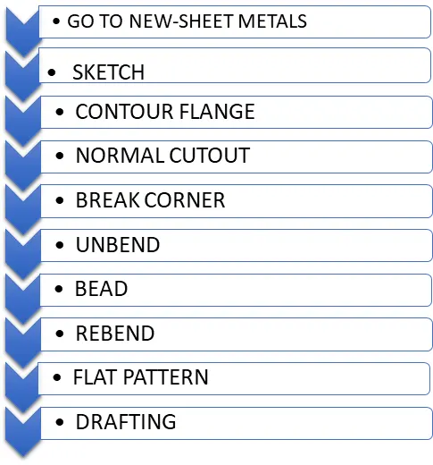
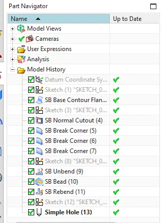
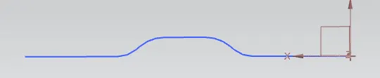
- SKETCH
It is a 2D representation of model.
- CONTOUR FLANGE
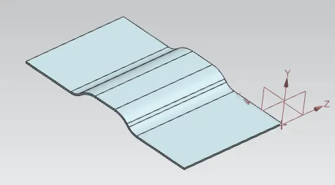
use the contour flange command to create a flange by extruding a sketch along a vector, or by sweeping a sketch along an edge or chain of edge. NX adds bends automatically using the default bend radius values. To use a different bend radius value, draw arcs in the sections, or change the default bend radius value.
- NORMAL CUTOUT
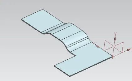
To cut material by projecting a sketch onto the model and then cutting perpendicular to the face intersected by the projection. Use planer sketches or 3D curves to specify the section for the normal cut out.
- BREAK CORNER
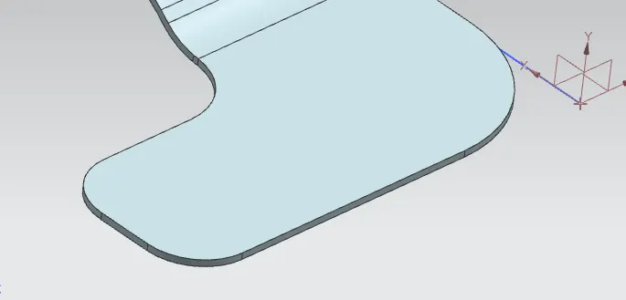
Use the break corner command to round or chamfer sharp corners of a tab or flange. Here we use different radius break corner.
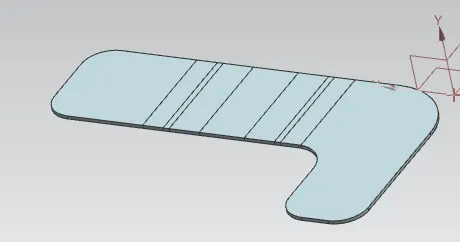
- UNBEND
Flattens the material which are adjacent to the bend.
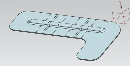
- BEAD
Use to strengthen the component, it lifts the material along the contour of a sketch that simulates a stamping tool.
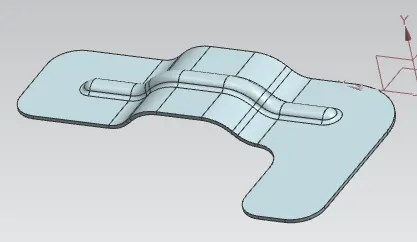
- REBEND
It restores the feature and comes back to previous bend state.
- FLAT PATTERN
- DRAFTING