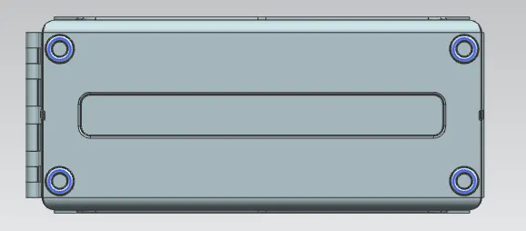
Advanced Sheet Metal Design Using NX Cad Challenge_2_Box Assembly
TITLE OF THE PROJECT
BOX ASSEMBLY
OBJECTIVE
The objective of this design is to create Box assembly with the help of NX advance sheet metal.
INTRODUCTION
Sheet metal is metal formed by an industrial process into thin, flat pieces. Sheet metal is one of the fundamental forms used in metal working, and it can be cut and bend into a variety of shapes. sheet metal is a semi- finished product that can be produced over a large area, whereby sheets are generally light, thin, stable, elastic and flat.
DESIGN APPROACH METHOD
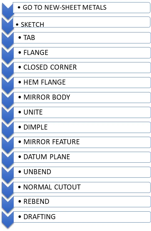
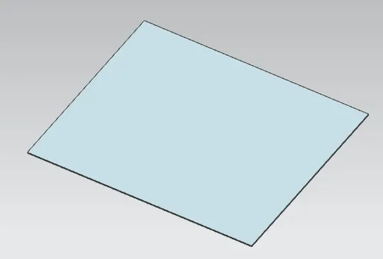
- TAB
This command to create a base feature by extruding a sketch along a vector by a thickness value, or by adding material to existing faces and bend regions of a sheet metal part.
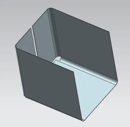
- FLANGE
To add a flat flange at an angle to a planar face and add a bend b/w the two. A flange consists of a bend region and a web.
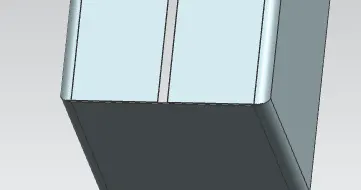
- CLOSED CORNER
Use the closed corner command to modify two flanges in one operation and to close the corner where the two flange meet during flattening the corner and relief geometry are made appropriate for a flat pattern.
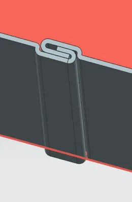
- HEM FLANGE
This command is used to modify an edge of a sheet metal part by folding it onto itself for the purpose of safe handling or to increase edge stiffness. Hem flange is always created as a secondary feature on a base part.
- MIRROR BODY
This feature is created replica of one or more profile with respective to axis required.
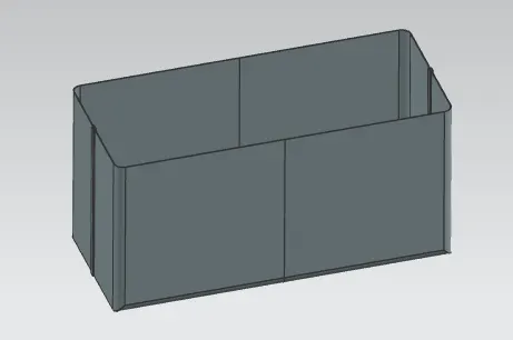
- UNITE
Combine 2 body and make it as one single body.
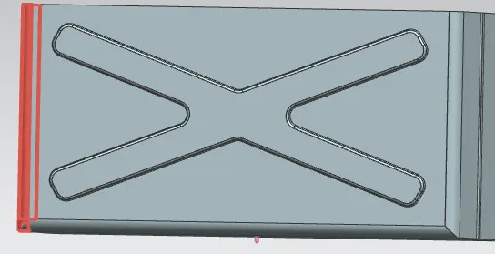
- DIMPLE
Dimple command to lift an area of the model inside a sketch that simulates a stamping tool. It can create an indentation in a sheet metal part using a sketched section as the dimple outline.
- UNBEND
Flattens the material which are adjacent to the bend.
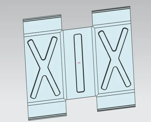
- REBEND
It restores the feature and comes back to previous bend state.
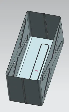
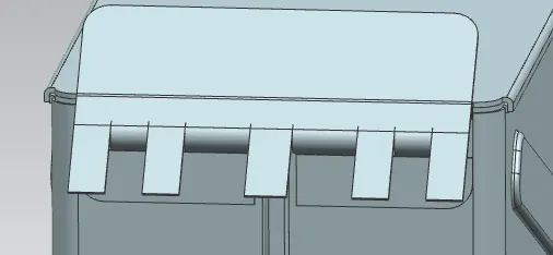
- NORMAL CUTOUT
To cut material by projecting a sketch onto the model and then cutting perpendicular to the face intersected by the projection. Use planer sketches or 3D curves to specify the section for the normal cut out.
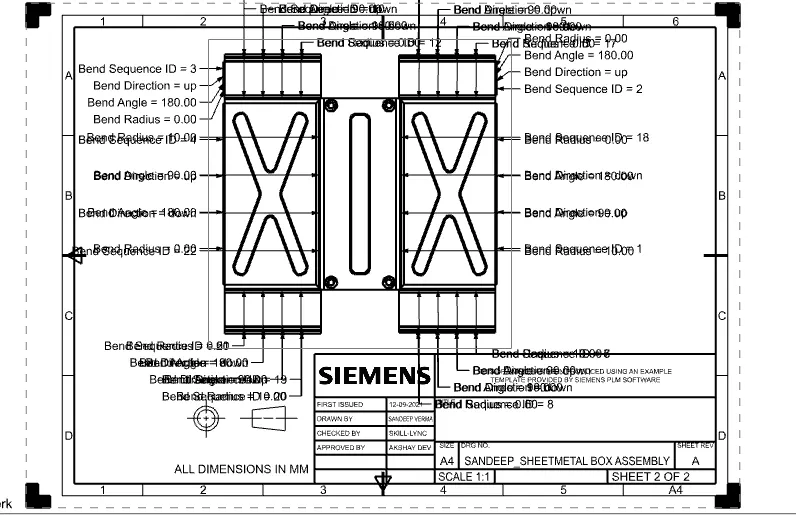
- DRAFTING
Converting a solid model to 2D sketch.
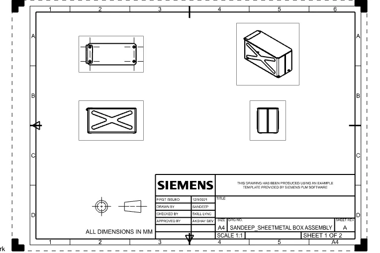
SCREEN SHORT OF MODEL
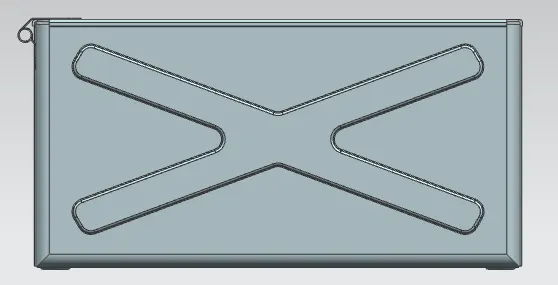
- FRONTVIEW
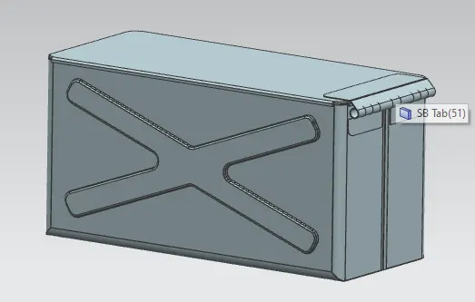
- ISOVIEW
- LEFTVIEW
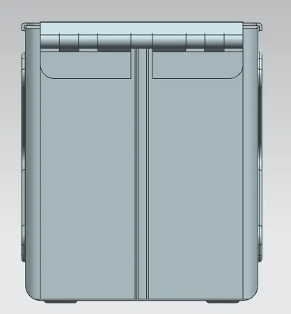
BACKVIEW