Radar Mast & Final Assembly of Yacht
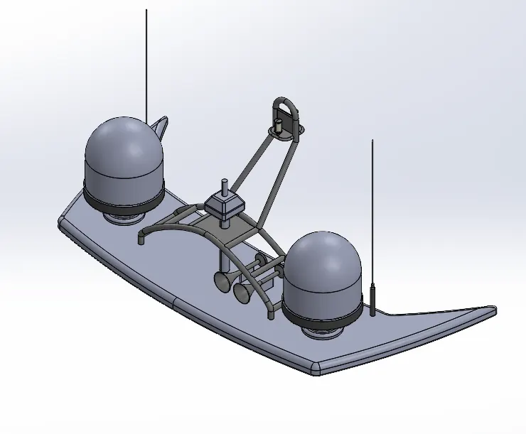
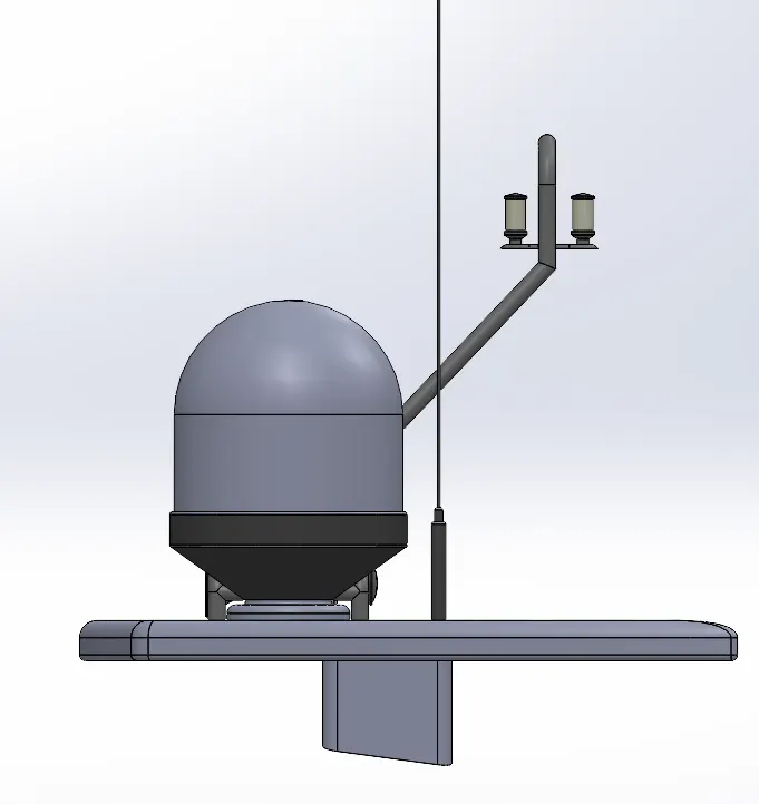
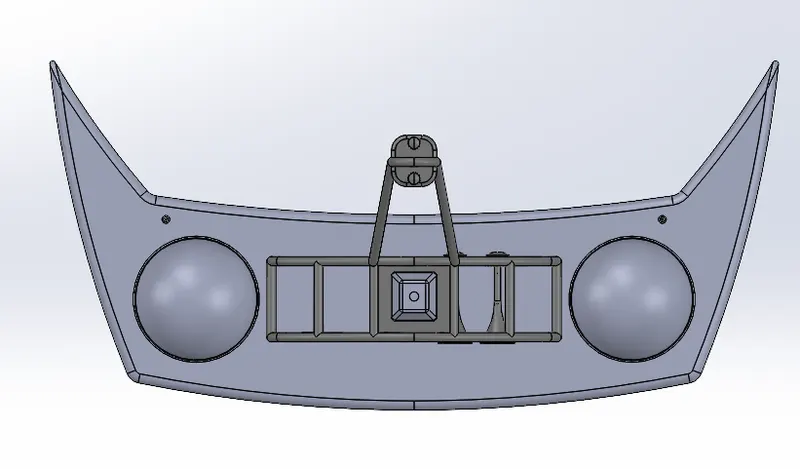
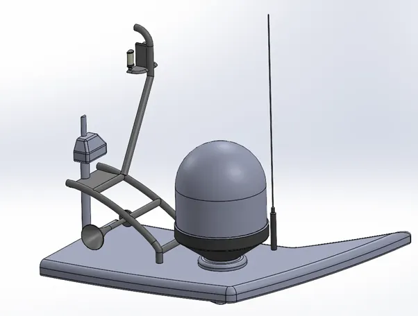
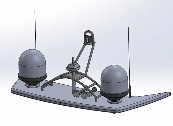
Radar mast-
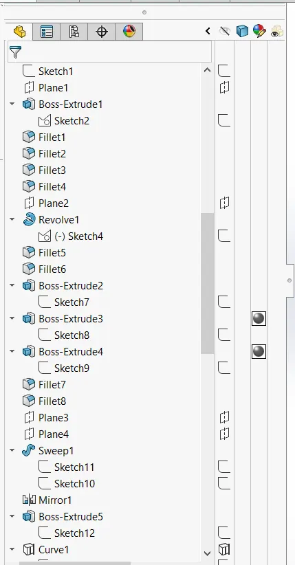
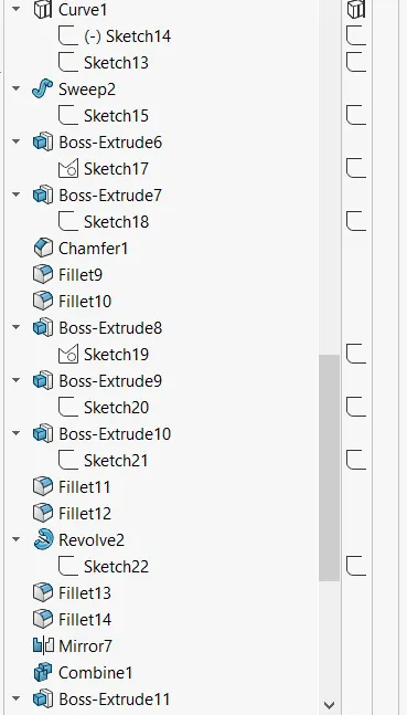
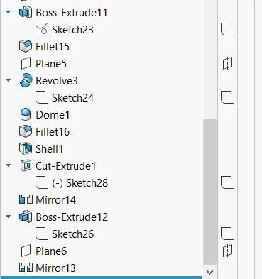
Design and Assembly of Yacht
Introduction-
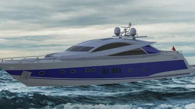
In this project I have learnt the designing of the YACHT in SOLIDWORKS trial version. Most of the features were created by surfaces features like, loft surface, swept surface extruded surface, offset surface, ruled surface and filled surface majorly and then the surface bodies were converted to Solid bodies.
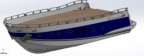
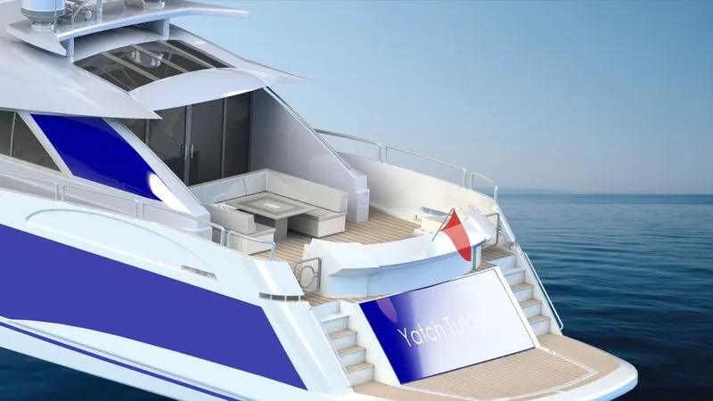
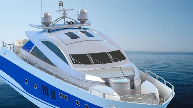
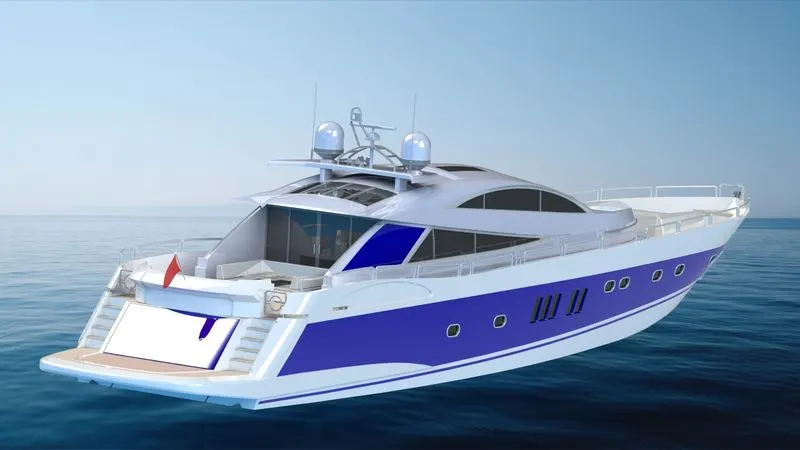
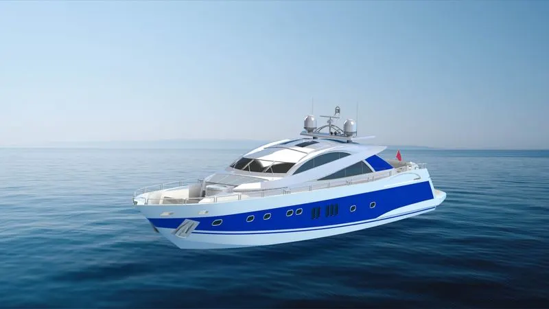
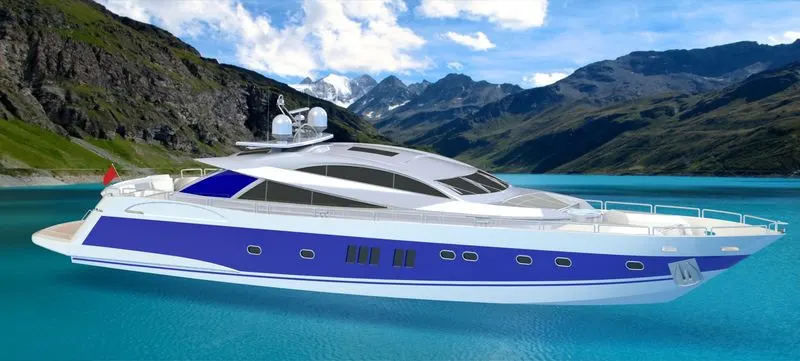
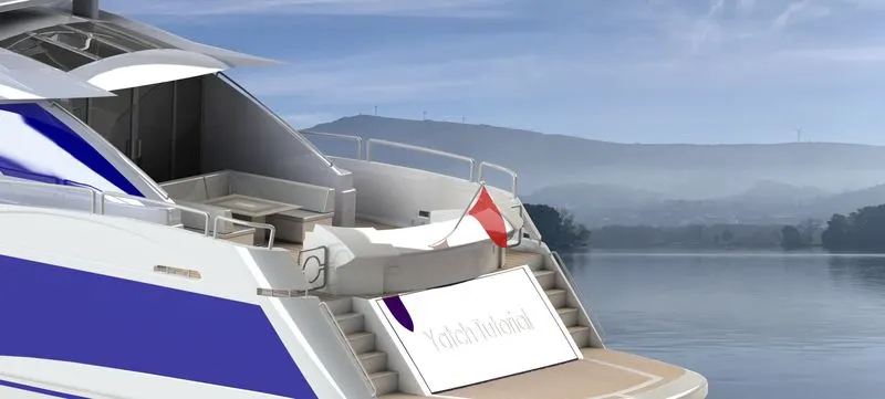
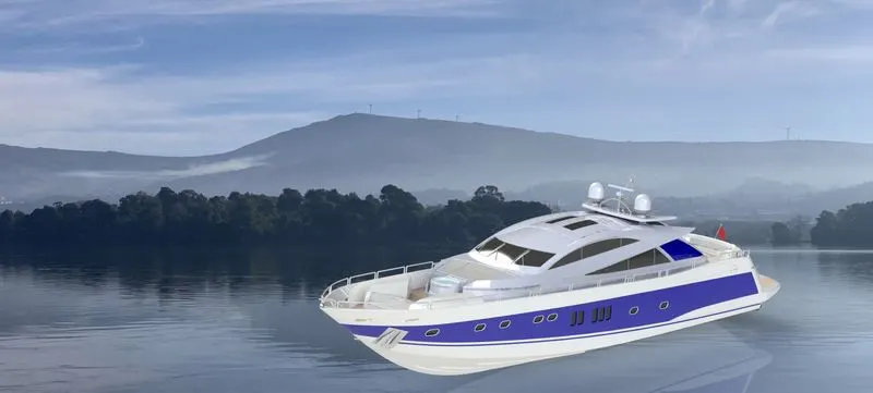
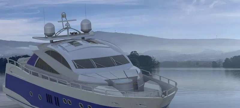
A total of 9 parts were designed separately and then were assembled by suitable mates. The parts are given suitable materialistic appearances and colours and the assembly is rendered in PHOTOVIEW 360 with environment and lighting to give it a realistic look.
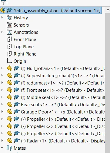
The 9 different parts are as follows-
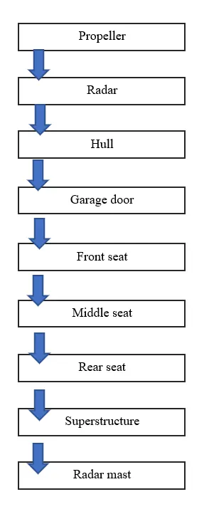
- Propeller
- Radar
- Hull
- Garage door
- Front seat
- Middle seat
- Rear seat
- Superstructure
- Radar mast.
Design methodology and approach-
The flowchart depicts the approach of my design-
Tool description and explanation-
The following are the features and tools which was used frequently to build Yacht-
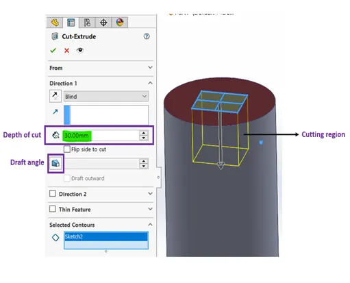
Extrude Cut –
This is similar to extrude but this is a material removal feature. It removes material from a body in which the shape is defined by the sketch.
We can see I am removing the solid in a rectangular shape in a depth of 30mm
This will result in removal of material in the yellow boundary as it shows in preview.
Extrude-
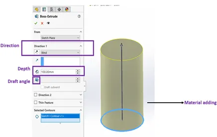
This is one of the most common tool which is used in the 3D modelling works. This is a material adding feature. It makes a 2d circle sketch to a 3D cylinder shape. It basically adds the material on a plane or a sketch.
To the right we can see the extrude/boss feature
The blue circle is the sketch, where it is extruded for 100mm in the upward arrow direction.
We can specify the direction above below
We can give a draft angle in the direction of extrusion, we can make it extrude in both directions same time.
Fillet and chamfer-
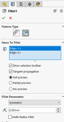
Fillet is an applied feature and does not need a sketch. It gives smooth round edges of a solid. In the below diagram there is a fillet of 3mm radius
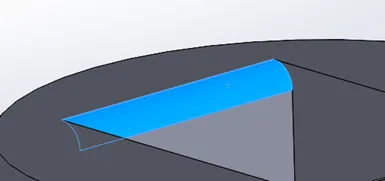
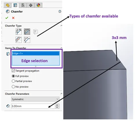
The chamfer is also an applied feature which creates a beveled feature on selected edges or vertex.
Revolved boss feature-
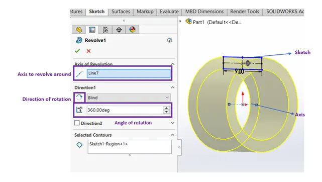
This is an material addition tool. This adds material in a circular shape or revolved shape with respect to an axis. This seems similar to the extrude but this works when we have to create a circular extrude like a ring shown below with an axis located near the origin.
We can also control the angle of revolve.
Shell –
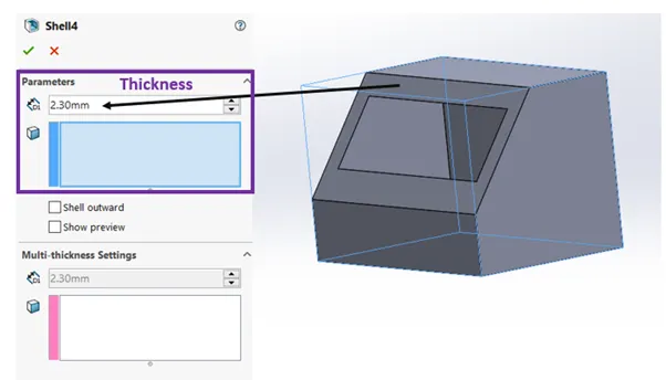
Shell is an applied feature which creates a hollow part. For example a solid cube when applied shell of some thickness the part will be converted to a hollow box by removing the cavity inside the part
Mirror-
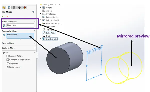
This is a very useful feature and time saving feature. When we need same details which are symmetrical in nature this is very useful in that case.
In the image below I can create another cylinder just by mirroring it across the plane/surface
Projected Curve-
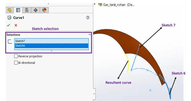
When I project a sketched curve onto a model face to create a 3D curve. You can also create a 3D curve that represents the intersection of two extruded surfaces generated by creating sketches on two intersecting planes. This is a very cool feature to use when we need curved in 3 dimensional.
Surface sweep-
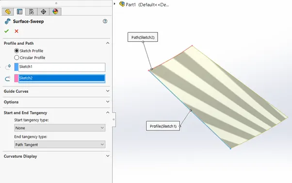
Sweep creates a material or surface by moving a Sketch along a path.
In the image below the sketch 1 is the profile and sketch 4 is the path.
Surface Loft-
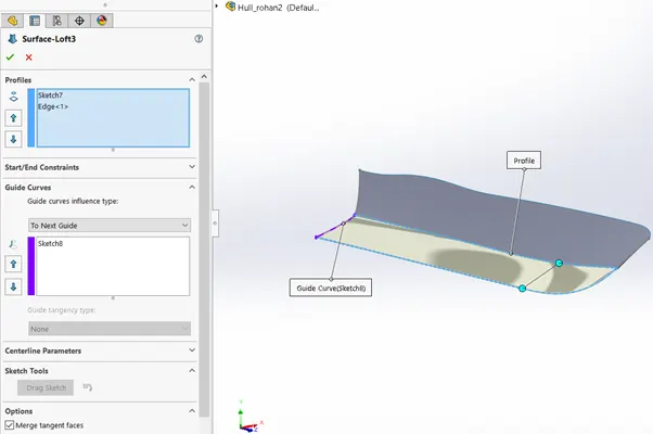
The loft feature creates a shape by making transitions between multiple profiles and guide curves. This tool is very valuable for modelling complex surfaces.
It is similar to sweep feature but this can handle multiple and complicated sketches.
In the below image the profile is guided with the centreline sketch, here we have achieved a varying size of the sketch.
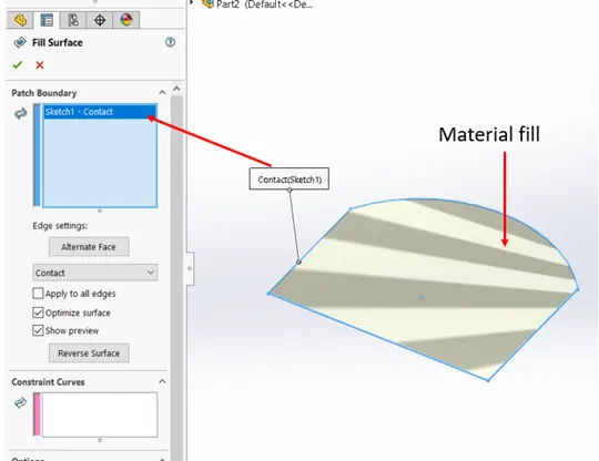
Surface fill-
This feature creates a material wrt the plane of sketch, and fills the sketch with material.
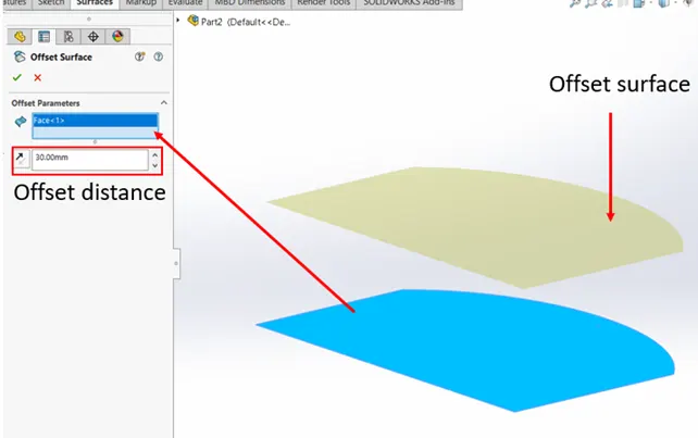
Surface offset-
This feature creates another identical surface with an offset distance.
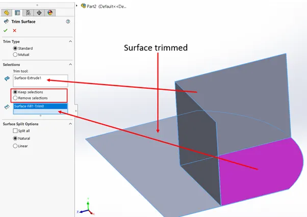
Trim surface-
This is a very useful feature in surface modelling. This trims our the surface by using another intersecting surface.
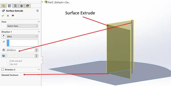
Extrude surface-
Knit surface-
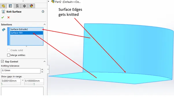
After all the surface features created, when we zoom in to the edges of the surfaces, we can see a small gaps between the surfaces, this means that the surfaces are not joint together they are separated by a small gap. So to join these edges SOLIDWORKS has a feature called “knit surfaces” which will join the edges and merge them.
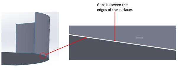
In the first image below we can see there is a slight gap when I zoom in at that edge. The blue edges in the image show that it is not knitted, if it has black edges it is knitted.
Assembly Mates-
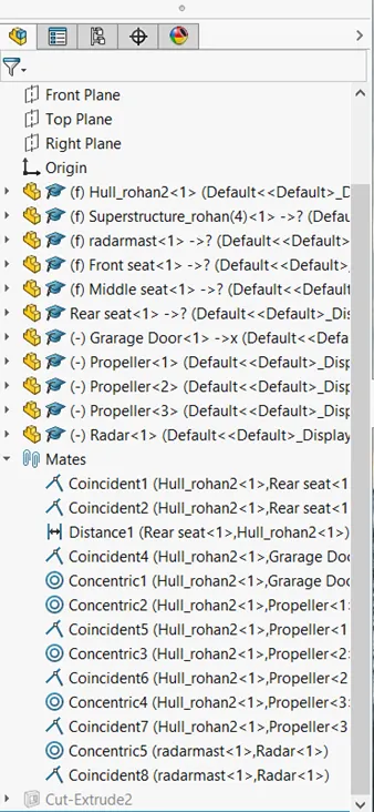
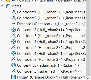
Mates in assembly mode create geometric relationships between assembly components. As you add mates, you define the allowable directions of linear or rotational motion of the components. You can move a component within its degrees of freedom, visualizing the assembly's behaviour. The right side image shows how many geometric relations are involved to mate/ constraint the parts which should result in fully defined.
Brief explanation of each part models-
Propeller-
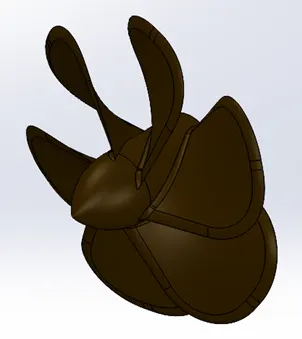
This part is built in a very simple way. The centre hub of the propeller is made by revolve feature. The blades are made by lofted boss feature. And finally the blades are circular patterned around the axis.
Radar-
This one is an easy part. A simple part with Extrudes and fillets. Screw holes are made by Cut extruding. And the screws are multiplied by using the sketch pattern. It is mirrored along the right plane and printed a text over the part.

Hull-
This is a very complicated part to design. This contains lots of splines, curves, projected curves, surface lofts, surface sweep, surface trims. Basically the lower part of the hull is created by using splines and projected curves.
The sketches for this part is made by taking blueprints as references.
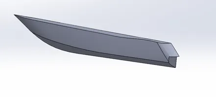
This much part is created by surface lofts, fills, and extruding, and then trimming it and knitting it and is made a solid body. Later this is made shell.
After this the deck surface is created by extruding, the rear surfaces are trimmed and filleted in shape. The windows are extruded by creating a different planes and sketching for each window.
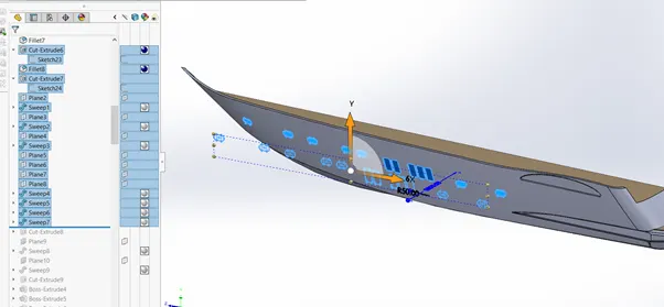
And then followed by extruding stairs at the rear end. And extruding the front hatch, and below the hull we have extruded.
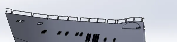
It is followed by creating railing by sweep feature and a headlight.
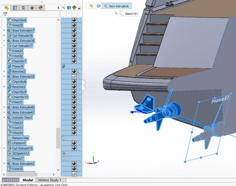
The suspension and the propeller shaft is created by extruding and revolve extruding features.
It is followed by creating and anchor in a new plane by features like extrude and chamfers.
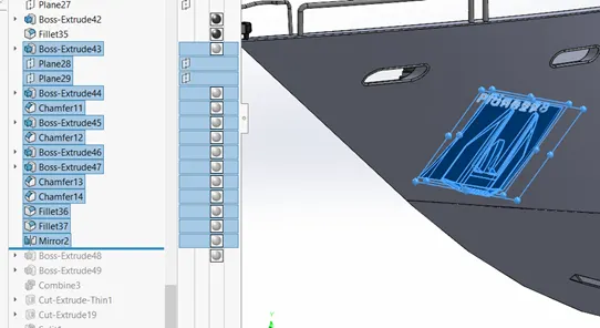
This was followed by cut extruding at rear end for the garage. After this it was mirrored to and merged the mirror body to the main body. Decals are also applied to the main deck floor and stairs.
Front seat-
This is also sketched by help of blueprints by keeping the hell deck surface as a reference.
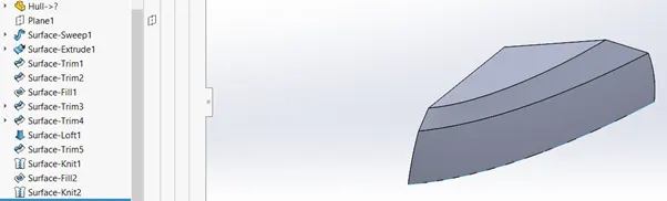
Primarily this body is created by using splines and curves and then converting it to surfaces by sweeping extruding surfaces and then trimming it accordingly and knitted.
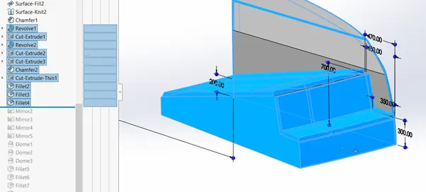
This is followed by creating the seats and cushion with same revolve and fillet features.
Then this is mirrored and dome features are applied to the part.
Middle seat-
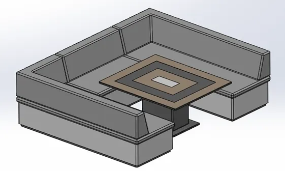
This is also simple to model. Blueprints are used as reference while sketching. This is just created by using boss extrudes and fillets and chamfers and a cut extrude.
Rear seat-
This is a little complicated part than the other 2 seats. This includes more surface features like surface extrude surface trim, extend, surface sweep and surface loft which is all knitted at the end
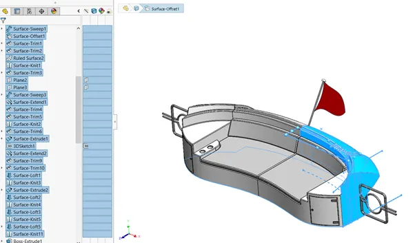
The seat and doors are created by sweep and extrude features and edges are filleted.
Superstructure
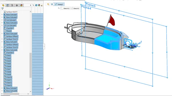
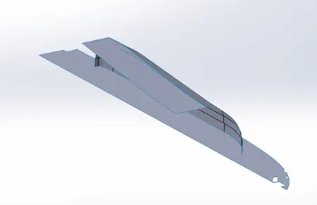
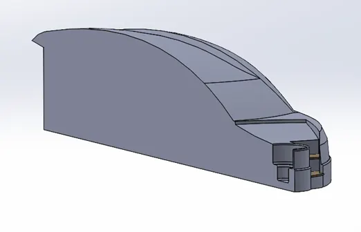
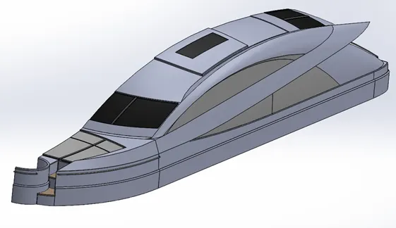
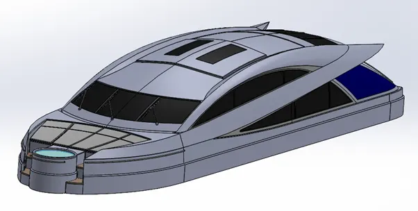
Superstructure is also a complicated part to design. It is created by lots of splines and curves, surface bodies and surface operations. It consists of designing the windows, doors window and frames with a jacuzzi and outer body in a aesthetically streamlined shape which is almost built as a surface body and then later converted to solid body by knitting and merging the surfaces.
Radar mast-
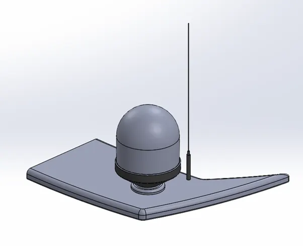
This part is simple and easy to design consists of antenna and signal receivers basically a communication module executed by boss extrudes and revolves and fillets
Rendered images-
Environment 1-
Environment 2-
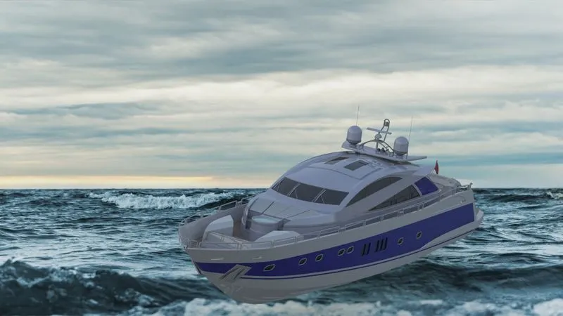
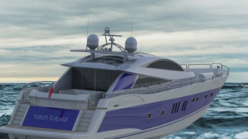
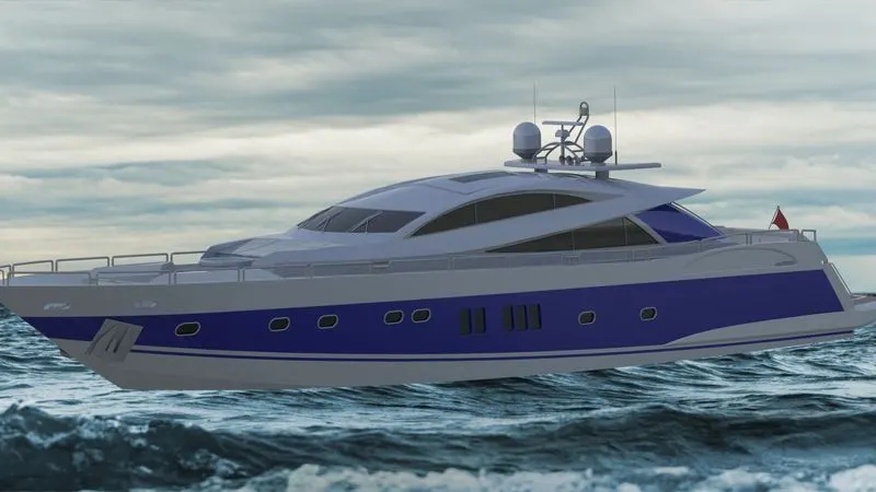
Environment 3-
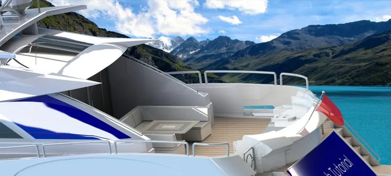
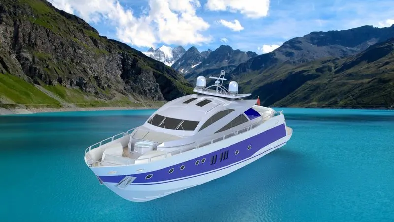
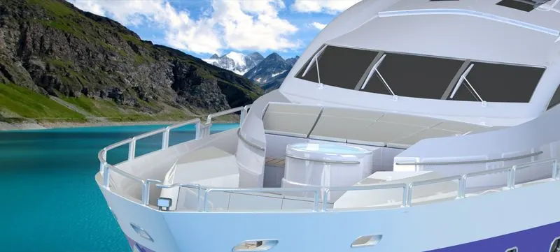
Environment 4-
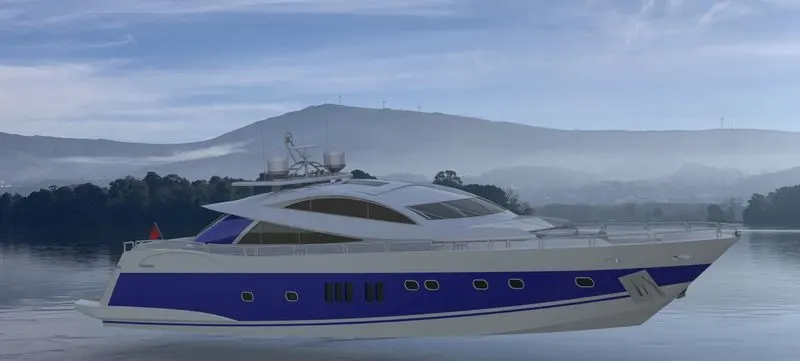
Environment 5-
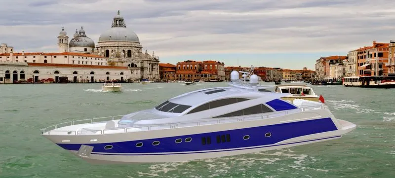
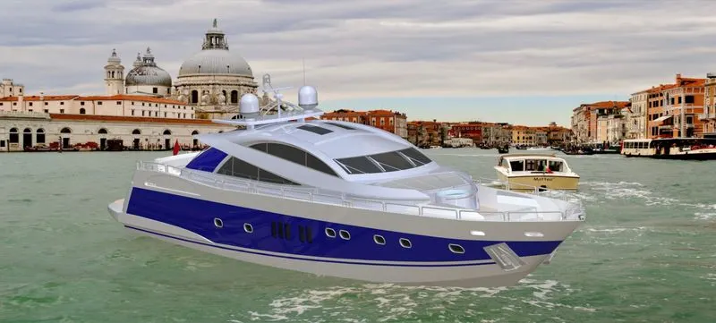
Assembly feature tree-
The Yacht model zip file link is here- https://drive.google.com/file/d/1nyVUEDawySdUCK77uzogx68jUNbIUwai/view?usp=sharing