Advanced Sheet Metal Design Using NX Cad Challenge_1_Casing Design
Sheet metal CASING DESIGN
Objective-
The aim of this assessment is to design casing in NX cad with sheet metal application. Basically, it is simple and easy to design which helps us to understand the basic features and techniques to be applied while designing.
Introduction-
This is a casing sheet metal, which is designed for holding equipment and clamping it tightly.
This is designed by using features like Tabs flanges, hems, normal cut-out, bending and unbending, dimples and beads.
Design methodology-
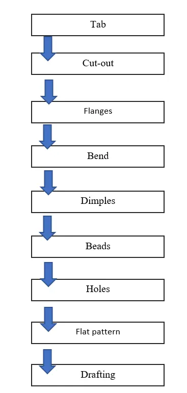
Description-
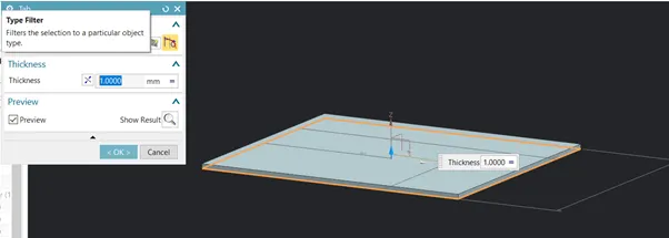
Tab- Basically we start with applying a tab feature to a sketch. The thickness is set to 1mm.
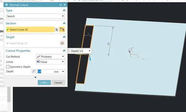
Normal cut out-
A normal cutout is made to the tab feature.
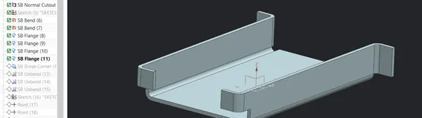
Bends and flanges-
The edges of the tab is bent and converted to flanges with 90 and other appropriate values.
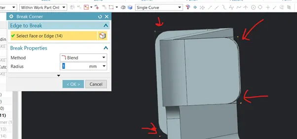
Break corners-
This feature is used to remove the sharp and pointy corners in the sheet metal, it gives round and smooth corners.
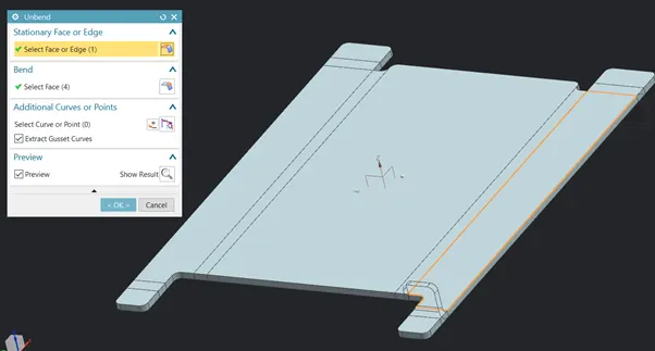
Unbending-
This needs to be done before using dimples and beads.
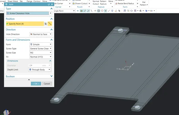
Applying holes-
We need apply screw holes at the edges. Therefore we define points and add screw holes at those defined points.
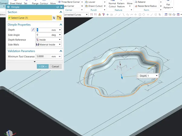
Dimple-
This feature is created to give a nice punch impression on the sheet metal. It needs a sketch to be executed and can work at specific depth values.
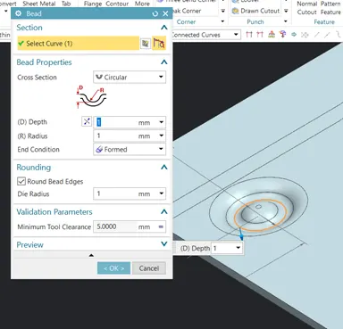
Bead-
This is created in circular cross section with appropriate values.
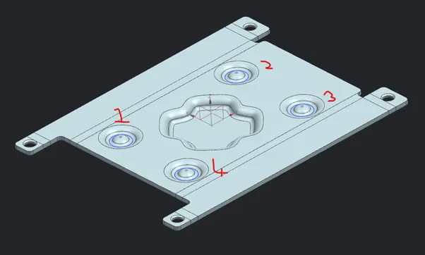
These beads are mirrored wrt to the planes and replicated to 3 others by using mirror feature option-
Flat pattern-
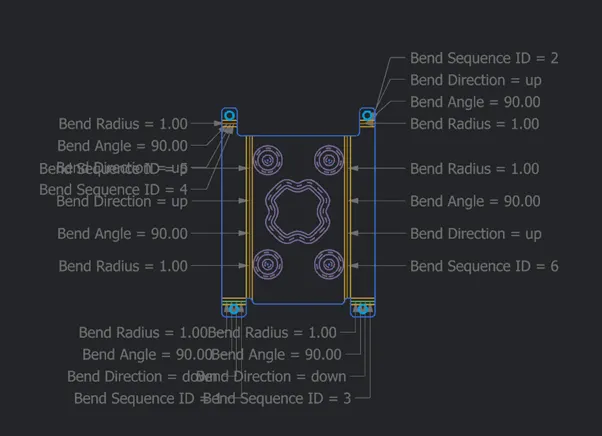
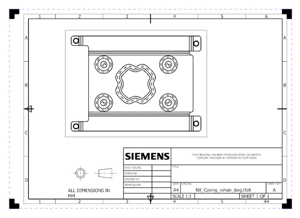
Flat pattern feature is used to flatten out the whole sheet metal with annotations. Which is used as a drawing in manufacturing.
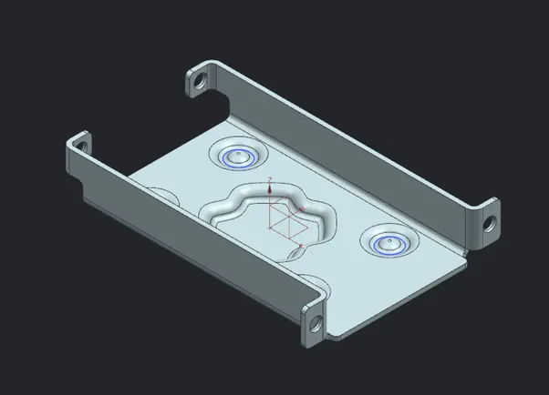
Images of model-
Iso view-
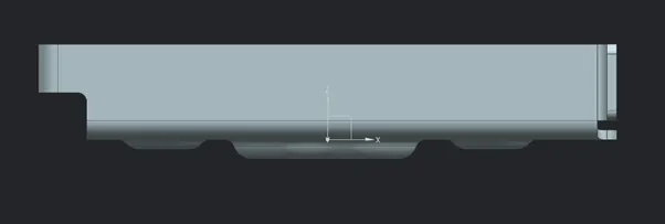
Front view-
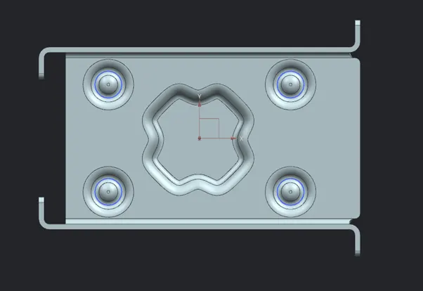
Top view-
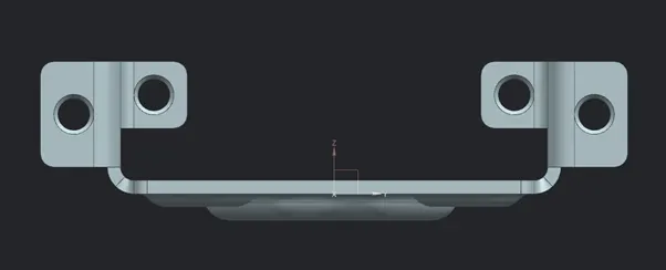
Side view-
Drawing sheet-
Conclusion-
In conclusion firstly this is just to know the basic features and tools used in sheet metal.
With all the necessary features I successfully created this model.