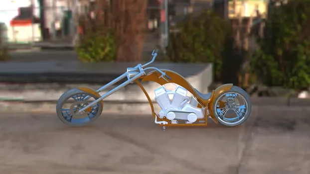
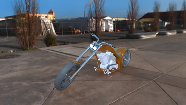
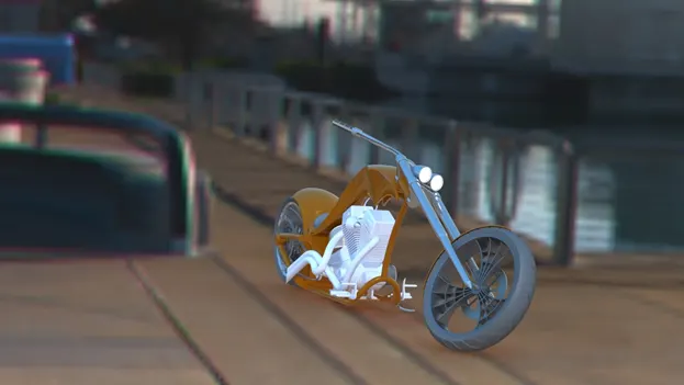
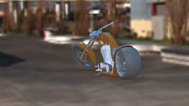
Photo Realistic Rendering
Modelling of American Chopper
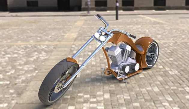
Objective-
The objective of this project is to learn sketching using various features and methods like lines circles, splines, curves, composite curves, creating planes etc. Developing 3d models like boss/extrude, Revolve, sweeps, Cuts, lofts fillets, shells, chamfers etc by using sketches. Also assembling the various parts to create a full 3d model of American chopper by using mates and assembly features, also by rendering in the specific environments and lights with decals.
Introduction-
This American Chopper 3D modelling was designed using SOLIDWORKS. Each of the individual parts are were sketched and developed into 3D model by using various features and tools available in SOLIDWORKS. The individual parts are assembled in SOLIDOWORKS by using many assembly features and mates This model is also rendered in different scenes using PHOTOVIEW 360 which is integrated in SOLIDWORKS
The different components of the model we have designed are as follows:
- Transmission belt
- Kick stand
- Front and Rear Fender
- Chain
- Oil Tank
- Foot pedals
- Front wheel and Rear wheel with webbed rims
- Front fork along with handlebars and headlights
- Chassis
- Engine, transmission box and exhaust
- Gas tank
Design methodology and approach-
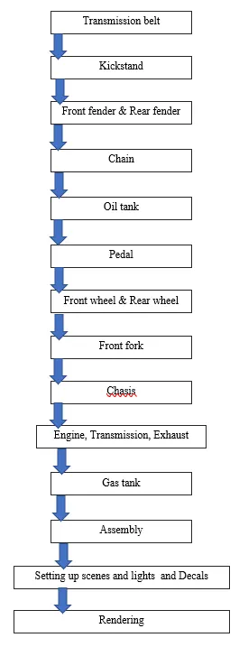
The flowchart depicts the approach of my design-
Tool description and explanation-
The following are the features and tools which was used to build model and assemble it-
Extrude-
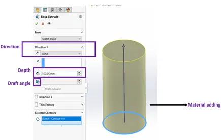
This is one of the most common tool which is used in the 3D modelling works. This is a material adding feature. It makes a 2d circle sketch to a 3D cylinder shape. It basically adds the material on a plane or a sketch.
To the right we can see the extrude/boss feature
The blue circle is the sketch, where it is extruded for 100mm in the upward arrow direction.
We can specify the direction above below
We can give a draft angle in the direction of extrusion, we can make it extrude in both directions same time.
Extrude Cut –
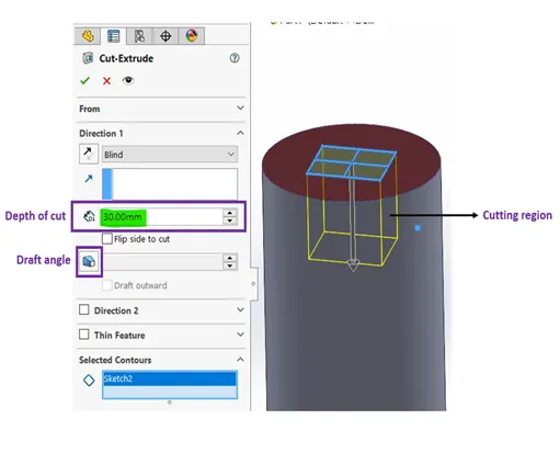
This is similar to extrude but this is a material removal feature. It removes material from a body in which the shape is defined by the sketch.
In the right we can see I am removing the solid in a rectangular shape in a depth of 30mm
This will result in removal of material in the yellow boundary as it shows in preview.
Fillet and chamfer-
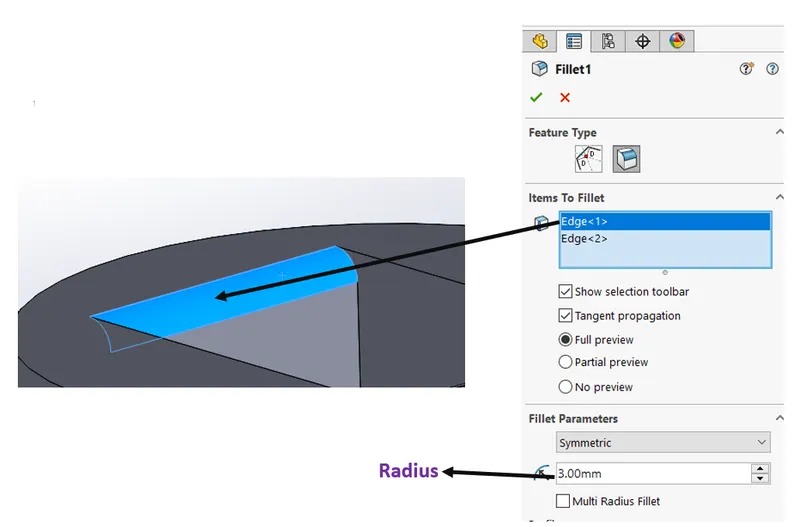
Fillet is an applied feature and do not need a sketch. It gives a smooth round edges of a solid. In the below diagram there is a fillet of 3mm radius
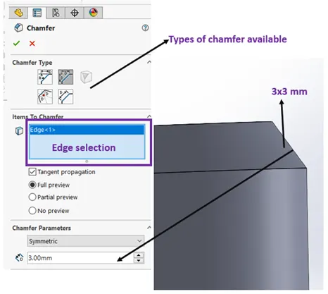
The chamfer is also an applied feature which creates a beveled feature on selected edges or vertex.
Revolved boss feature-
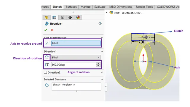
This is an material addition tool. This adds material in a circular shape or revolved shape with respect to an axis. This seems similar to the extrude but this works when we have to create a circular extrude like a ring shown below with an axis located near the origin.
We can also control the angle of revolve.
Shell –
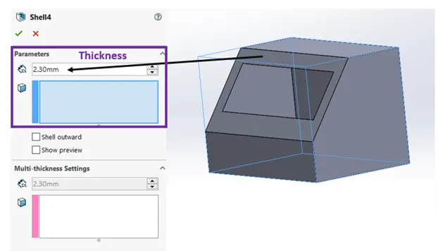
Shell is an applied feature which creates a hollow part. For example a solid cube when applied shell of some thickness the part will be converted to a hollow box by removing the cavity inside the part
Sweep Boss –
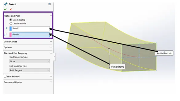
Sweep creates a material or boss or surface by moving a Sketch along a path.
In the image below the sketch 1 is the profile and sketch 4 is the path.
Loft boss-
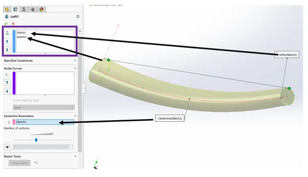
The loft feature creates a shape by making transitions between multiple profiles and guide curves. This tool is very valuable for modelling complex surfaces.
It is similar to sweep feature but this can handle multiple and complicated sketches.
In the below image the the profile is guided with the centreline sketch, here we have achieved a varying size of the sketch.
Mirror-
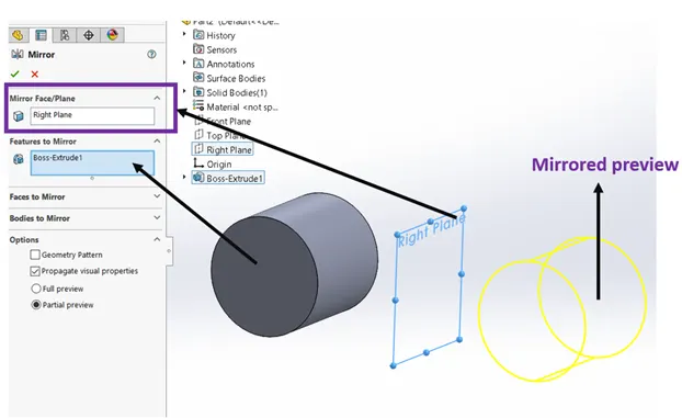
This is a very useful feature and time saving feature. When we need same details which are symmetrical in nature this is very useful in that case.
In the image below I can create another cylinder just by mirroring it across the plane/surface.
Linear Pattern-
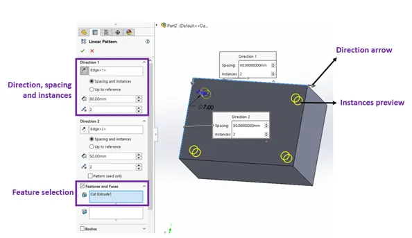
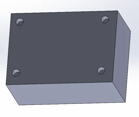
Linear pattern can be used when we need to create instances of the same feature in a linear direction. For ex like creating holes at the corners. This is also a very time saving feature. Similar to linear pattern we have Circular pattern, Guided curve pattern, mirror pattern, sketch driven pattern etc,.
Projected Curve-
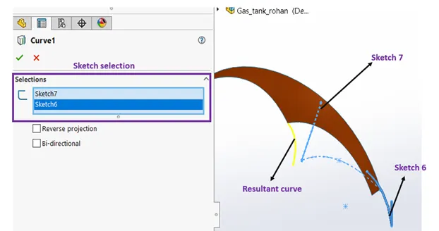
When I project a sketched curve onto a model face to create a 3D curve. You can also create a 3D curve that represents the intersection of two extruded surfaces generated by creating sketches on two intersecting planes. This is a very cool feature to use when we need curved in 3 dimensional.
Mate-
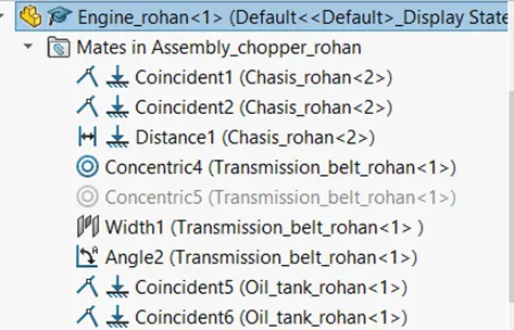
Mates in assembly mode create geometric relationships between assembly components. As you add mates, you define the allowable directions of linear or rotational motion of the components. You can move a component within its degrees of freedom, visualizing the assembly's behaviour. The right side image shows how many geometric relations are involved to mate/ constraint the parts which should result in fully defined .
Brief explanation of each part models-
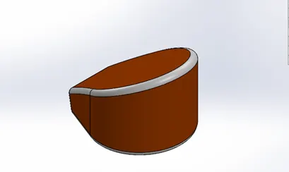
Transmission Belt-
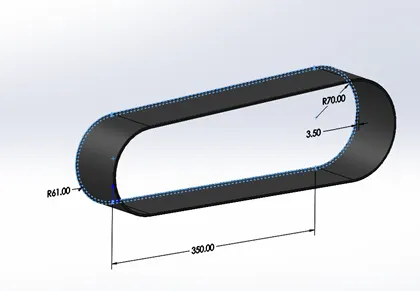
Transmission belt is rubber part. It is just extruded from a sketch and is filleted in the edges. And is given a matte rubber appearance.
Kickstand-
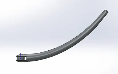
This part is created by the loft feature. 2 sketch profiles and a guide curve is needed to use this feature. A new plane was also created to do a sketch as per the design. Dome feature was used to get rounded edges. Extrude cut feature was used to cut off the geometry near the mating region.
Front fender and rear fender-
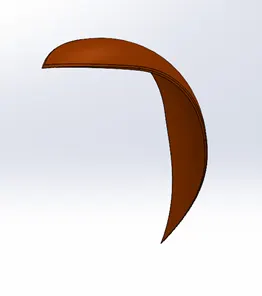
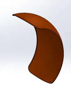
Revolve feature is used in these parts, split tool was used to cut off and give a nice curvy shape around the ends of fender which was sketched by using splines.
Chain-
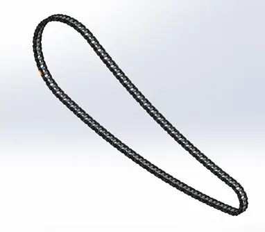
This was a tedious part, it involved same features repetedly. Features like Curve guide pattern, creating a sketch block, inserting a sketch block, giving relations to sketches and extruding it. First thing the shape of the chain was sketched and created chain links as 2 sketch block. Then chain links were added in form of blocks and were given relations to keep it through the guide curve of the shape of the chain.
Oil tank-
This is a hollow part, by using shell feature the hollowness was achieved. The shape of oil tank was obtained by using combine feature. It combines 2 different shape and gives out a commin shape with respect to the 2 shapes. Fillet feature was used to give rounded edges.
Pedal-
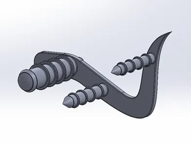
This part sketch contains splines, and circular bosses. This feature involved extrude, linear pattern, revolve extrude and fillet features to get the desired shape.
Front wheel & rear wheel-
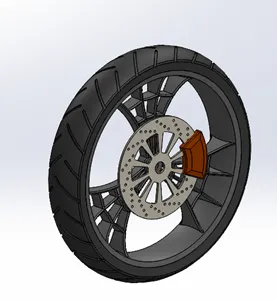
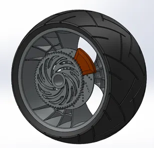
Both wheels are similar in deisgn but inly the size is different, This is kinf of complicated part.It begins with revolve extrude of 360 degree of rim, it is followed by designing of spider webbed rims by using splines and arcs. And giving a circular pattern for the extruded webbed rims and combining with the rim completely. It is follwed by brake creating caliper and rotor disc. It is followed by designing the tire with threads and using offset extrude features to get the threads.The rear wheel has extra body of sprocket. The entire wheel consists of five solid parts Chrome finished Rims, Sienna metal painted Caliper, Chrome finished sprocket and matte rubber tires.
Front fork-
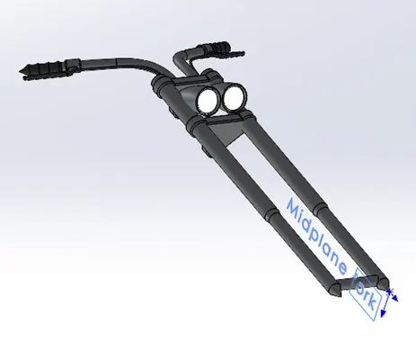
This part consists of front fork, handle bar, head lights, break and clutch lever, cables and handle grips. Since this part is symmetric along its height only half part can be designed and then mirrored. This starts with revolve extruding the forks, then comes the handle bars by which is designed by using splines, and making it projected curves. Then the part was mirrored to get a full part. Head lights were also added and “area lights” appearance was given to it. The remaining fork is chrome and has rubber grips.
Chassis –
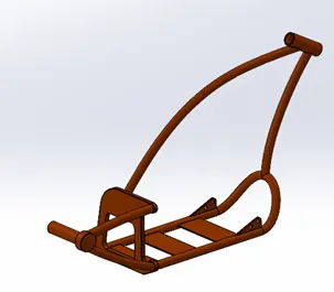
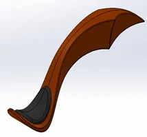
Most of the sketches in this part contains splines ad arcs which are converted to Projected curves and composite curves. And is swept along the curves to get a chassis frame. Also it has a resting surface for engine. The lower portion of this is mirrored. All of the edges are filleted. A hinge for kickstand is also given to it, thee surface for Foot pedals are also provided by simple extruding. The frame for rear wheel is also done by splines and provided with axle.
Engine, Transmission and Exhaust -
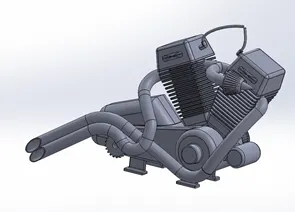
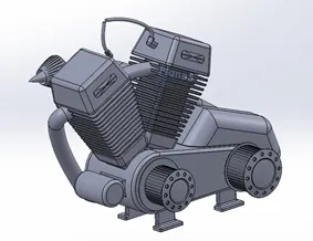
The base of the engine is created in a plane which is extruded in midplane, the surfaces are again sketched and bosses are created. At the left side of engine driving and driven pulley are sketched and revolved to accommodate transmission belt with teeth on the circumference which were created by simple sketch and giving it a circular pattern. The cylinders are made by creating a plane in a angle and sketching a square and extruding in opposite directions separately with draft. The fins are created on the cylinder for heat dissipation by extrude cut and giving it a linear pattern, and all the cylinder were filleted. The cylinder is given circular pattern of 1 instance. The Starter motor is also allocated on the front. With the help of splines and curves we can get a exhaust systems from 2 cylinders. The Chrome appearance is given for this body.
Gas tank –
In this we use surface section of modelling and features in surface section. Projected feature is also used in this model. Features like Loft, Boundary surface, knit surface, This part is also built in half and then mirrored to get full part. This part a hollow by using shell feature. This is also accommodated with a seat. The appearance is sienna.
Assembly –
All the above parts are assembled in solidworks. This is a quite simple operation but depends in number of parts. In case of the American chopper, since the parts were less it is simple to manage.
Beginning with chassis, as we know chassis is like the skeleton of a motorcycle the whole assembly is done with reference to chassis. As we load the chassis in out assembly environment, we directly fix it in the space. Then the following parts are assembled with chassis using chassis’ plane and references of chassis surfaces. A number of mating features are available based on geometrical features.
After every part assembling and mating we need make sure it is fully defined and no loose ends should be there.
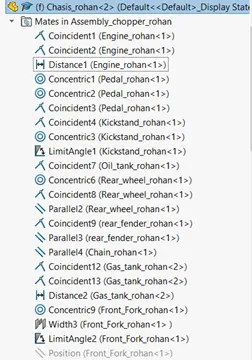
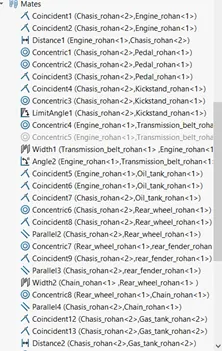
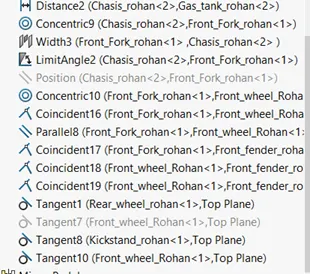
Above image shows all the mates that are done during assembly, that list indicates all the that are done between the parts.
Rendering-
Rendering is the process of generating a photorealistic or non-photorealistic image from a 2D or 3D model by means of a computer program. The resulting image is referred to as the render. Multiple models can be defined in a scene file containing objects. The scene file contains geometry, viewpoint, texture, lighting, and shading information describing the virtual scene. The data contained in the scene file is then passed to a rendering program to be processed and output to a digital image.
The image here is a normal graphical image, which vaguely displays of how the product looks. This is not a rendered image.
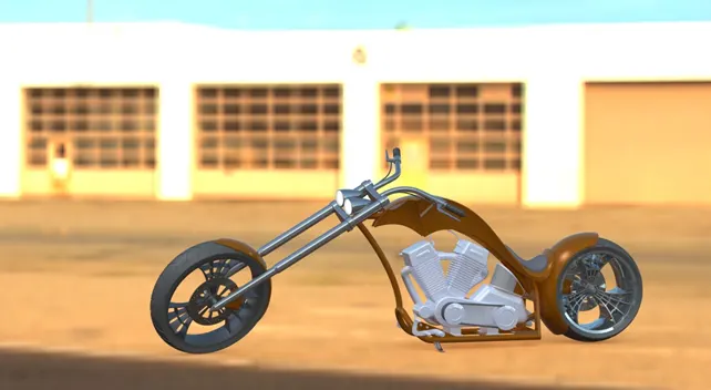
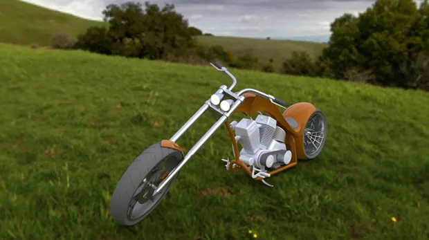
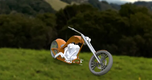
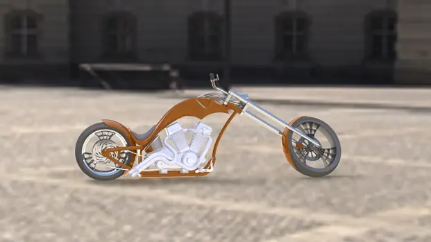
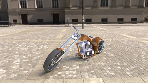
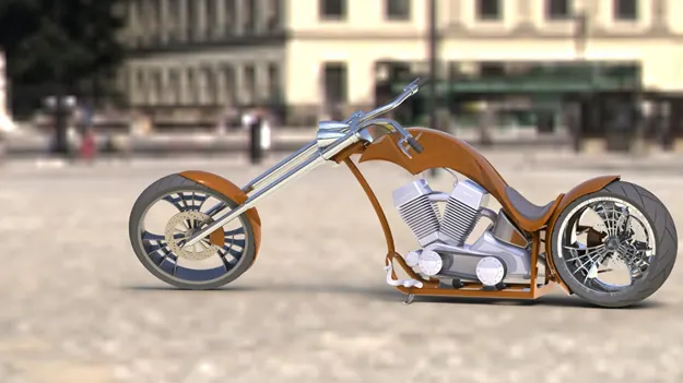
While rendering, the appearances that is allotted to the parts like, tires have rubber and engine has a chrome material appearance. In a normal view it just depicts a color of the material, in the adjacent image all the parts look similar other than color, but after rendering with a background and lightings which will result in giving a close realistic view of how it will appear in the real world.
In this image we can see the metallic colours and appearances, we can distinguish rubber of tyre and the chrome metallic rim of the wheel. Not only appearance but also gives out reflections of the surrounding scenes and lights.
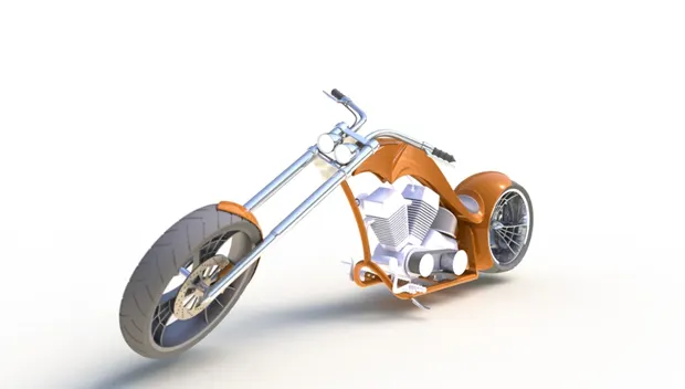
Rendered Images in Different scenes with PHOTOVIEW 360 -
- Urban 05-
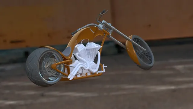
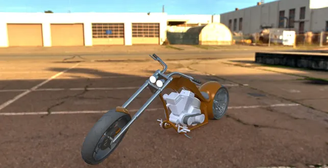
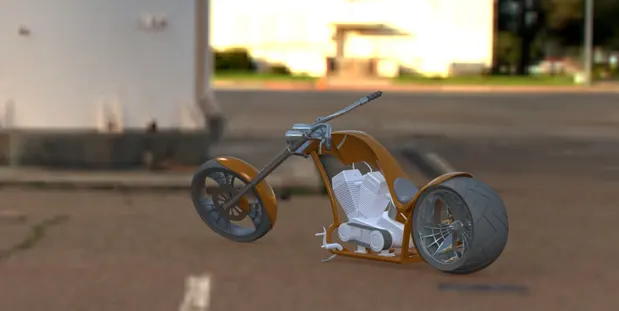
Landscape 02-
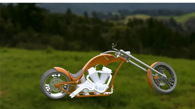
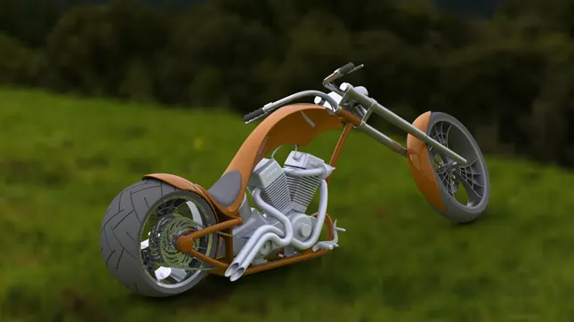
- Daytime-
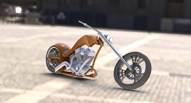
- Urban 02-
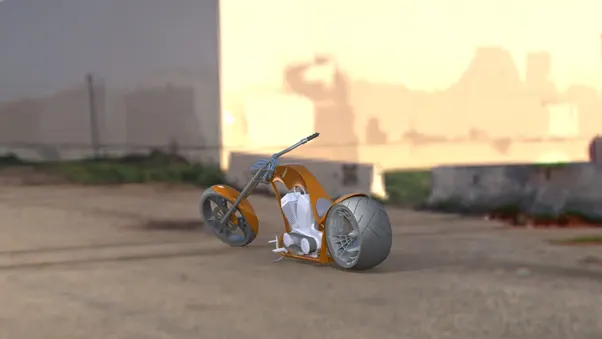
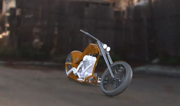
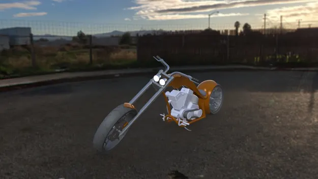
- Urban 03-