Advanced Sheet Metal Design Using NX Cad Challenge_6_Bracket
Bracket
Objective-
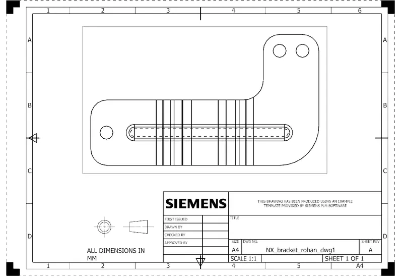
In this assessment, I have learnt to create a sheet metal Bracket from a drawing sheet by using necessary features step by step in order.
Introduction
In this firstly, I created a contour flange by a sketch & used normal cutouts, break corners, Unbending, adding holes and bead. This was a simple one but did it from a drawing sheet.
Design methodology-
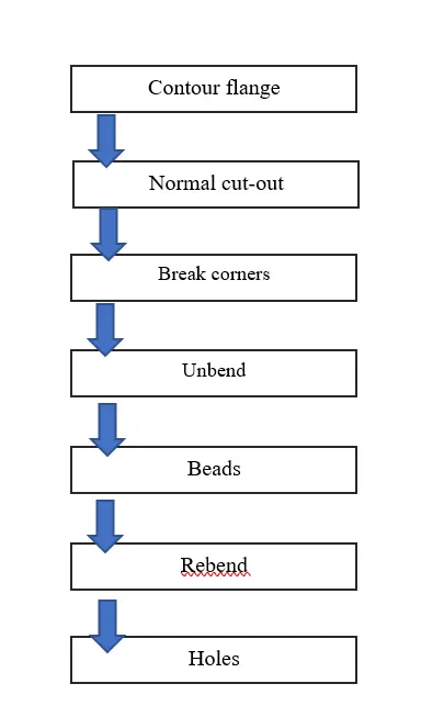
Description-
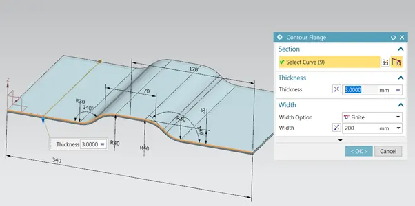
Contour flange-
Contour flange is a type where we can get a tab surface and a flange in 1 operation. It just needs a 2d sketch and it can create sheet metal from that sketch in the respective shape.
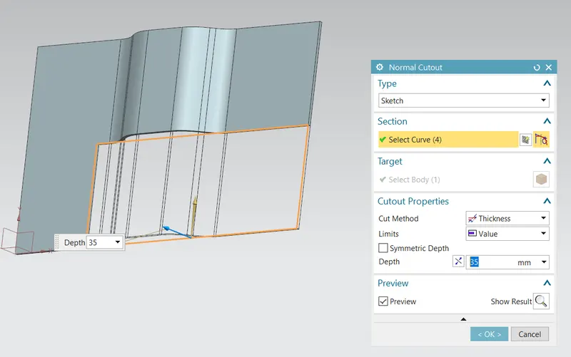
Normal cut-out-
This feature is used for material removal. A part of the contour flange is removed by defining a sketch
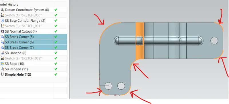
Break corners-
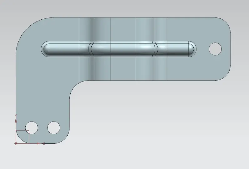
This feature is used to remove sharp corners and give a smooth round corner of a particular radius. In this bracket, I have used a radius of 25, 30 & 60mm.
Bead-
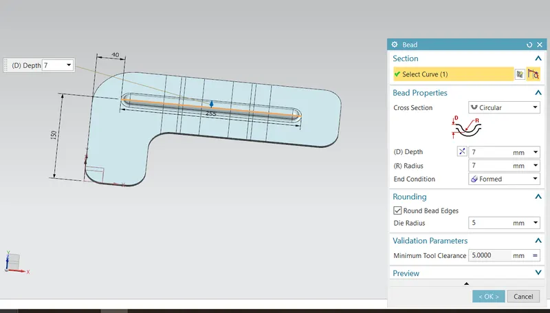
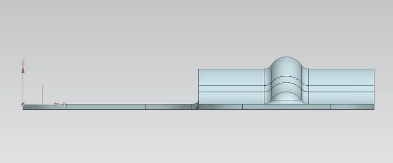
This is a feature that adds strength to the sheet metal. So to add this feature we need to unbend the sheet metal and then proceed to add a bead of dimensions specified.
Holes-
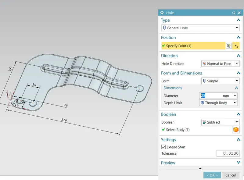
General holes are added to the sheet at 3 positions defined by dimensions. The hole diameters were 20mm.
Images-
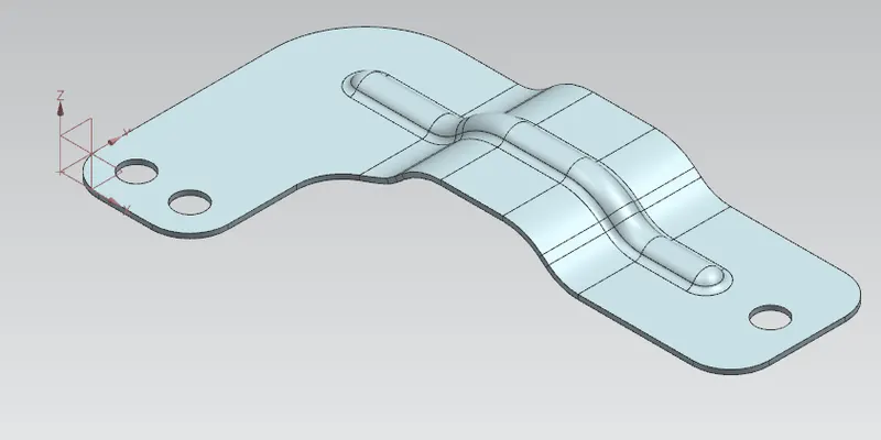
Iso view-
Front view-
Top view-
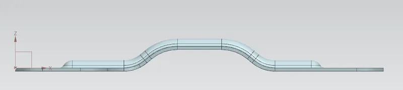
Right side view-
Conclusion-
The model was successfully designed by using a drawing and the necessary steps in sequence.