Radar Mast & Final Assembly of Yacht
DEAR SIR
PLEASE CONSIDER MY CHALLENGE SUBMISSION.
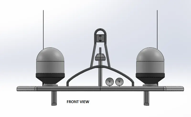
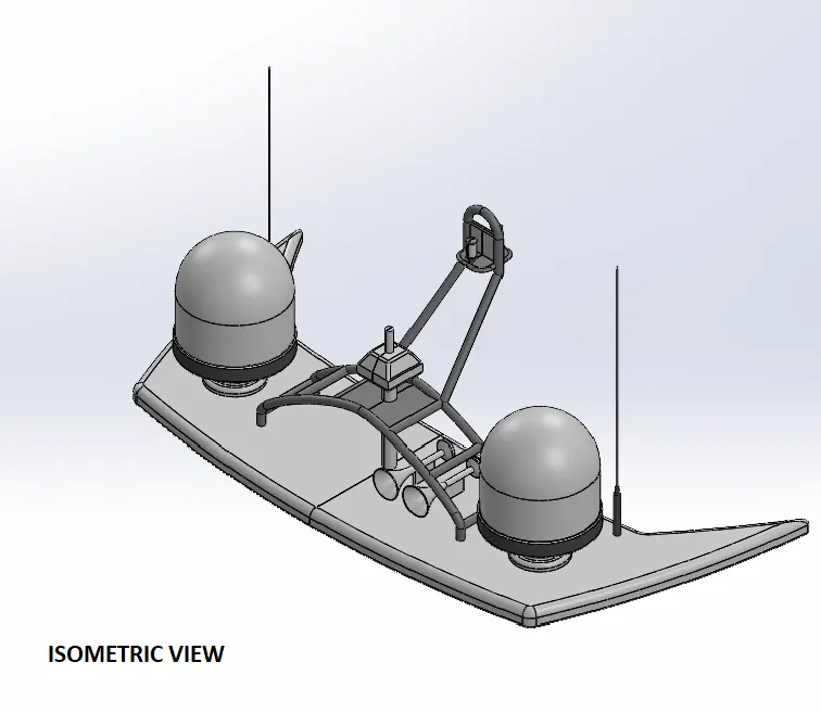
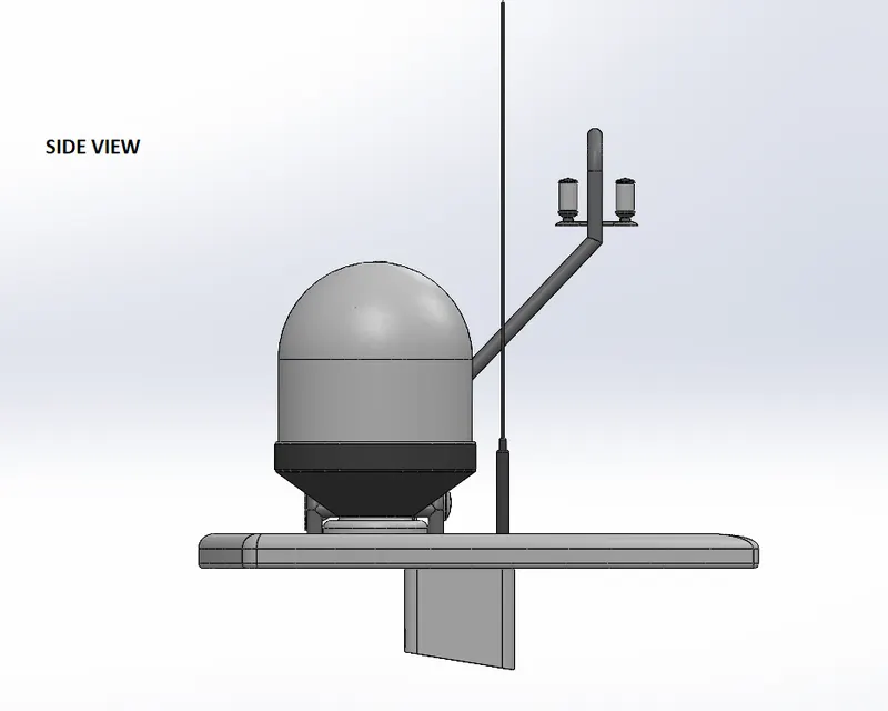
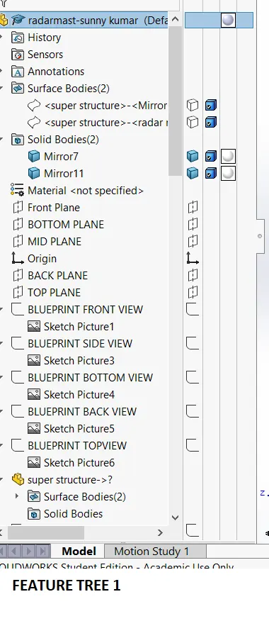
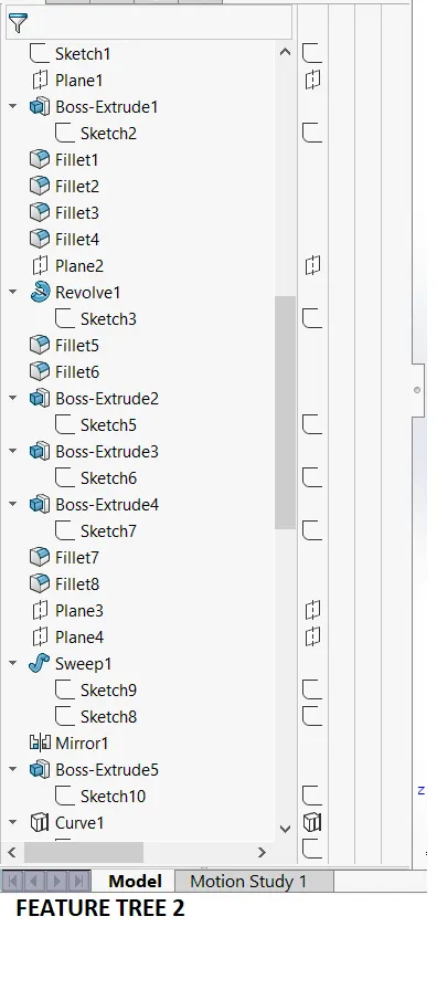
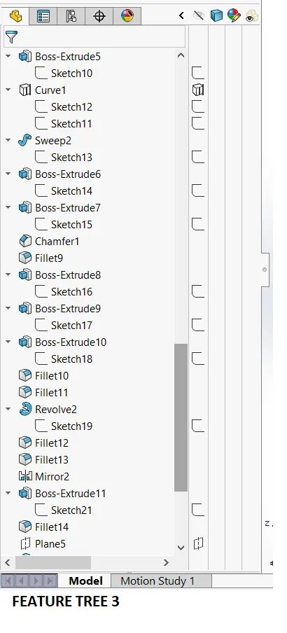
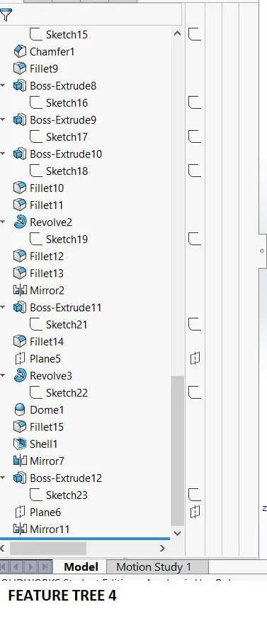
1. RADAR MAST
2. YATCH ASSEMBLY
REPORT ON YATCH MODELLING
------------------------------------------------------------------------------------------------------------------------------------------
TITLE -
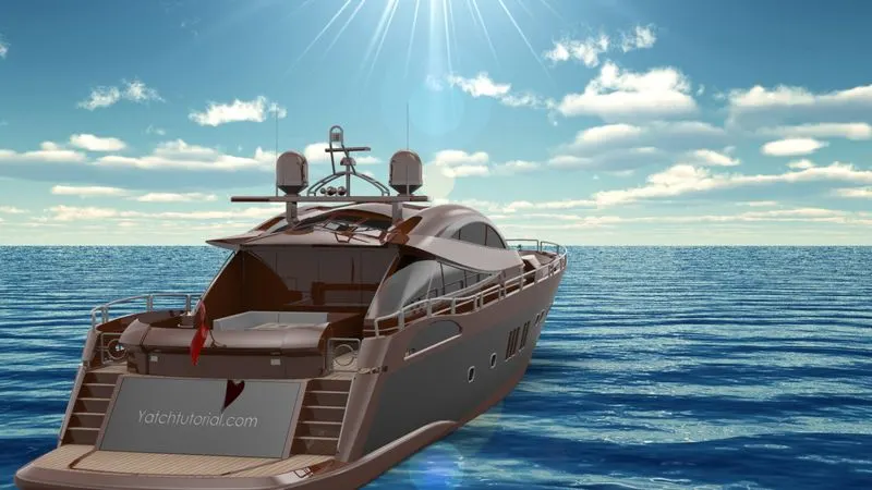
SUNSEEKER PREDATOR YACHT
Objective
- To design and model the parts of Sunseeker Predator Yacht.
- Assemble the parts to produce the final model.
- Perform some photorealistic rendering for the model.
Introduction
A yacht is a sail or power vessel used for pleasure, cruising or racing. Cruising yachts may be designed for near-shore use or for passage-making. They may also be raced, but they are designed and built with the comfort and amenities necessary for overnight voyages. Qualities considered in cruising yachts include: performance, comfort under way, ease of handling, stability, living comfort, durability, ease of maintenance, affordability of ownership. Depending on size, a cruising yacht is likely to have at least two cabins, a main salon and a forward stateroom. In smaller yachts, the salon is likely to have convertible berths for its crew or passengers. Typically, the salon includes a dining area, which may have a folding, built-in table. The development of reliable power plants created a new category of pleasure craft. The power plants for yachts started with the steam engine and transitioned to the internal combustion engine. Originally the material for all yachts were made of wood, using a wooden keel and ribs, clad with planks. These materials were replaced with iron or steel in steam yachts. In the 1960s fiberglass became a prevalent material. Larger yachts are more likely to be constructed of steel, aluminum or composite fiber-reinforced plastic. Through this project with the aim to acquire skill in CAD, we are designing a Yacht in Solidworks. For the design we predominantly use surface modeling because the hull and superstructure include irregular and curvy geometries. Solid modeling comprises a minor portion for this design.
METHODOLGY
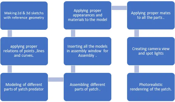
Each and every parts such as Hull, superstructure, various seating arrangments on the deck, garage, radar, radar mast, propellers and its associated components, stabilizers etc were modelled and assembled.
Various commands and features I used to model the parts are as follows.
2D sketch: A 2D sketch is the base to create a 3D model. It is created on plane on 2 axes. Various line tools, circles, rectangles, splines etc are mainly used to create sketches.
Tools such as 'Power trim, 'Trim extend' etc. were widely used in this project.
Projected curves : Used to project a sketched curve on to a model face to create a 3D curve. It can be also created by creating sketches on two intersecting planes.
Trim: Used to remove the extra edges of intersecting lines on a 2D sketch.
Offset: Used to add sketch entities by offsetting faces, edges, curves etc to a specified direction and distance.
Convert entities : Convert selected model edges or sketch entities into current sketching plane.
Boss Extrude: It is used to extrude a sketch or selected contours in specified directions thus creating a solid feature.
Revolved Boss: Revolves a sketch or selected sketch contours about an axis, thus forming solid feature
Swept Boss: Sweeps a closed profile along an open or closed path to create a solid feature.
Extruded Cut: It removes material from a 3D model according to the selected profile along specified direction.
Revolved Cut: It removes material from a 3D model according to the selected profile about a specified axis.
Loft: The loft feature helps to create shapes by making transition between multiple profiles and make use of guide curves to form complex geometry.
Dome: A dome is a smooth rounded vault forming the outside face of a body or structure.
Fillet : used to connect adjacent faces with a specified tangent curve.
Chamfer: Used to connect adjacent faces with a specified inclined line.
Combine: It is used to combine two or more solid bodies together.
Extended surface: Used to extend the selected edge of a surface along a specified direction and distance.
Ruled surface: It is used to insert a ruled surface according to the selected edges.
Offset surface: Creates offseted surface using one or more faces.
Surface fill : Create a surface patch within a selected boundary.
Boundary surface : Creates a boundary surface between profiles in two directions.
Lofted surface: It is used to create lofted surface between two more profiles.
Trim surface: It is used to remove the unwanted portion of a surface according to a sketch profile or other features.
Shells: Used to hollows out a part, leaves open the faces we select and creates thin walled features on the remaining faces.
Assemblies: Used to build complex assemblies consisting of many components which can be parts or other assemblies called subassemblies.
APPROACH OF MODELLING
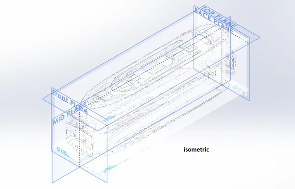
BLUEPRINT SETUP -
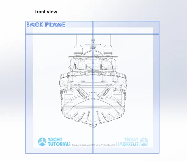
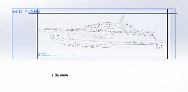
YACHT Objective is to make a Blueprint setup in order to model the yacht. In order to make the blueprint setup, we need side view sketch, bottom view sketch, back view sketch, front view sketch and Top view sketch.
Each image was brought to respective planes and applied required dimensions and positions. Suitable scaling was done. This procedure was followed for other images too. Screenshot of final Blueprint setup is shown below.
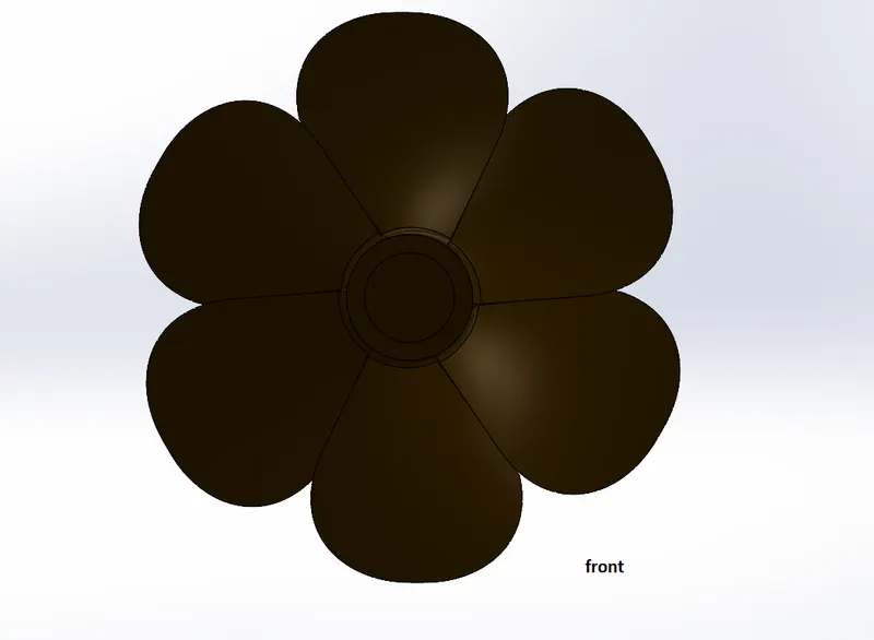
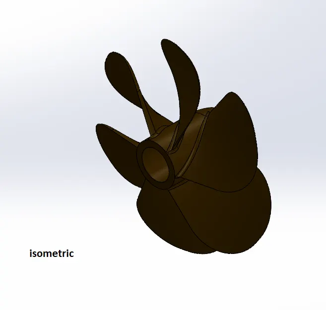
Propeller :
A mechanical device that create thrust over fluid by to propell system.
It has serval rotational blade. This component mainly used in aeroplane, submarines, ships to propell them. features and tools used are mentioned below-
Feature Tools: - Revolve Boss/Base, Cut Extrude, Circular Pattern, Fillet .
Sketch tools: - Line , spline ,3point corner rectangle ,circle.
Surface Tools:- Lofted Surface
Circular Pattern: - This feature make many exact replica of selected part and organize it in circular way with equal distance or angle.
Solid Loft: - Add material between two or more profiles to create solid bodies.
Radar:
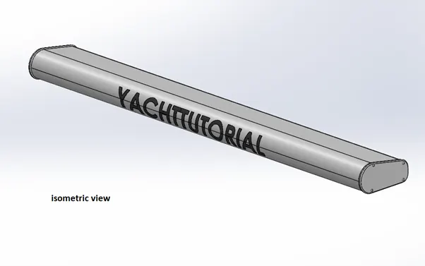
A electronic detection system that send electromagnetic waves to detect angle, range, velocity of object like ship, submarines, aircraft, space craft etc. In modelling of Radar, we used following tools.
Feature Tool: - Boss Extrude, Fillet, Cut Extrude, Mirror. Split line
Sketch tool: -Sketch entities, Sketch Patter.
Sketch Pattern: - It patterns features, faces, and bodies based on sketch points.
Split line: - This creates a break point on line to make a segment into two.
Hull: -
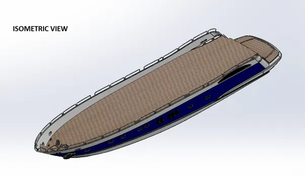
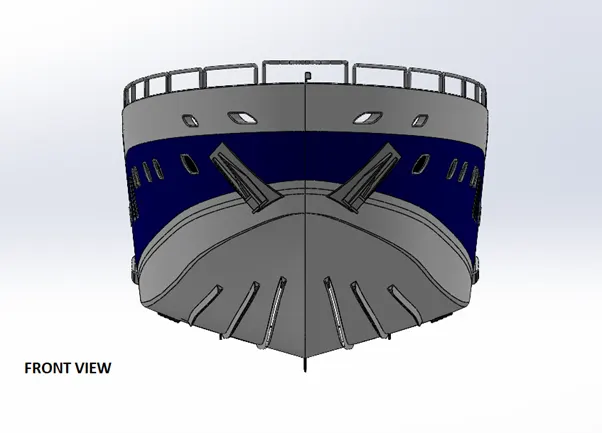
It is the main component of complete Yatch Assembly. Rest of other component will be installed on hull it is like base structure. The hull of a ship directly interacts with water and therefore is the most crucial consideration to a designer. Thus, the hull has to be designed from a pure hydrodynamic point of view. This is intrinsically related to the resistance, propulsion and hence, the powering proportions of a ship. Hardly do we observe a ship which is blandly a box-shaped one. Stability of Ship and ease of construction are also key deciding factors. Designing the precision lines of a hull form keeping in view all these aspects is the bedrock of any form of ship design.
In design of hull following tools used
Feature tools: - Projected curve, Boss-Extrude, Combine, cut Extrude , Fillet, Chamfer, Swept Boss, Revolve, Dome, Linear Pattern, Helix and Spiral, Delete Face, Shell.
Sketch tools: - Sketch Entities, Convert Entities, Offset Entities, trim Entities.
Surface tools: - Surface Loft Surface trim, Surface Extrude, Surface Knit, Surface Fill.
Projected curve: - Projects a sketched curve onto face or sketch.
Composite Curve: - It combines two projected curves into a single one
Helix/Spiral: - Add a helix or spiral curve from a sketched circle.
Linear Pattern: - Create multiple instances of a part, sketch in linear way having equal distance as specified.
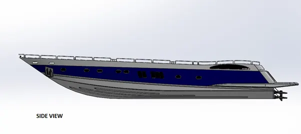
Garage Door:
Garage is used to store vehicle like Bike, car etc. Garage door helps to lock garage space.
In design of door we used following tools
Feature Tools: - Cut-Extrude, Shell, Fillet, Mirror.
Sketch Tools: - Sketch Entities like line, circle, etc.
Shell:- It remove extra material from solid part to create thin walled surface and making hollow one by adding thickness.
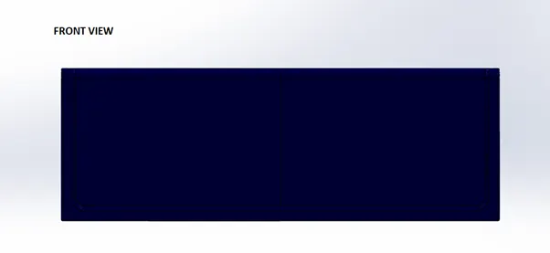
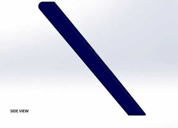
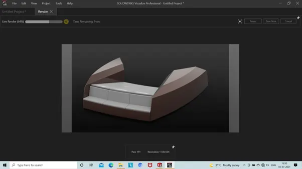
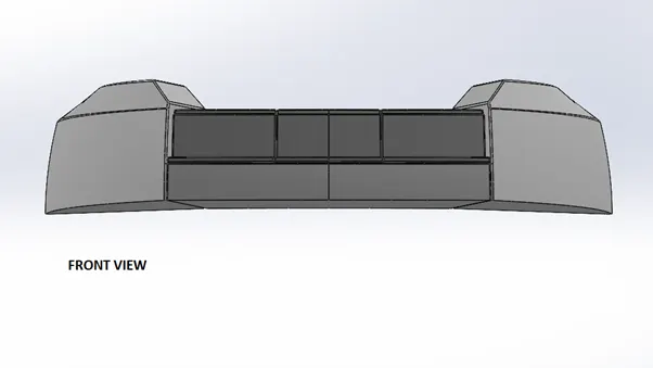
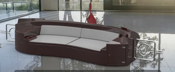
Front Seat –
Seats are mean to have rest to occupants. Front seat lies exactly in front of superstructure in between of that we small water pool. Front seat designed using surface features and some of solid features with reference to deck surface. Here we used dome feature to give shape like cushions.
In design of front seat, we used following tools
Feature tools: - Revolve, Cut Extrude, fillet, Mirror, Dome, Chamfer.
Sketch tools: -sketch Entities, Convert Entities.
Surface tools: - Inset Surface, Swept Surface, Extrude Surface, Surface Trim, Surface Fill, surface Loft and Surface Knit.
Surface Extrude: - This helps to generate or to create a surface from a single sketch entity like line.
Filed Surface: - This constructs a surface patch within a boundary defined by curve, edges or sketches of existing model.
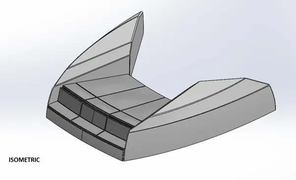
Middle Seat:
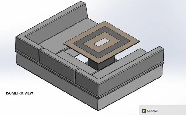
Middle seat is situated next to superstructure.
It is modelled with reference to deck surface.
Feature tools: -Boss Extrude, Cut Extrude, Mirror, Fillet, Chamfer.
Sketch tools :-Sketch Entities, Convert Entities, Offset Entities.
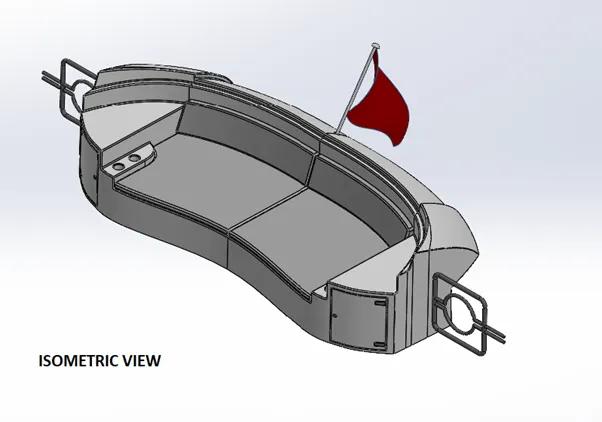
Rear seat:
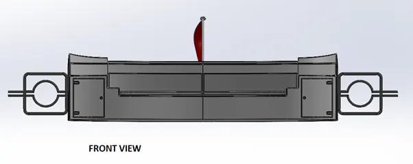
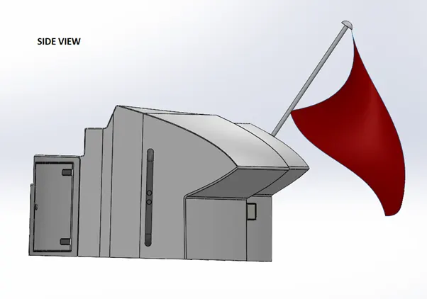
Rear seat located at the end of deck. We used many surface features to model this seat with reference to deck surface. A flag is modelled with 3D sketch giving a real look to it as it shows during wind flow.
Feature tools: - 3D sketch, Boss Extrude, Cut Extrude, Chamfer, fillet, Swept Boss, Mirror, Revolve. Sketch tools: -Sketch entities Trim Entities, Offset Entities, Convert entities.
Surface tools: - Inset Surface, Swept Surface, Offset Surface, Trim Surface, Ruled Surface, Knit surface, Extend Surface, Loft surface,
Offset Surface: - This creates surfaces at some distance away as specifies from referenced plane face.
Extend Surface: - This command gives extension to existing surface up to next plane , face , or sketch as specified.
Superstructure:
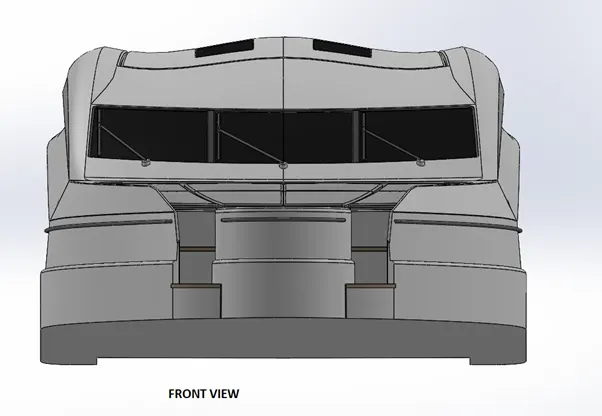
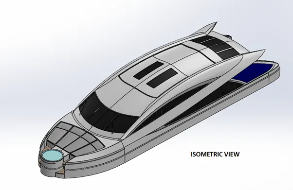
It is the extension above deck surface of hull which houses accommodation, offices, Signal and Communication unit, utility spaces, and multifarious electrical and electronic system areas which are indispensable to the operation and the functionality of the ship as well as the sustainability of crew.
A good superstructure serves following objectives
- Fulfilment of operational requirement in terms of available volume
- Provision of enough height and space of deck.
In design of superstructure, height plays a crucial part. Height of superstore must enough to provide proper navigational line of sight also it must be in the limit of stability.
In design of superstructure we used following tools,
Feature tools: -3D sketch, Projected Curve, Boss Extrude, Cut Extrude, Chamfer, fillet, Mirror, Dome.
Sketch tools:-Sketch entities, Trim Entities, Offset Entities, Convert entities.
Surface tools: - Inset Surface, Extrude Surface, Swept Surface, Offset Surface, Trim Surface, Ruled Surface, knit surface, Extend Surface, Loft surface, Surface Fill, Delete Face.
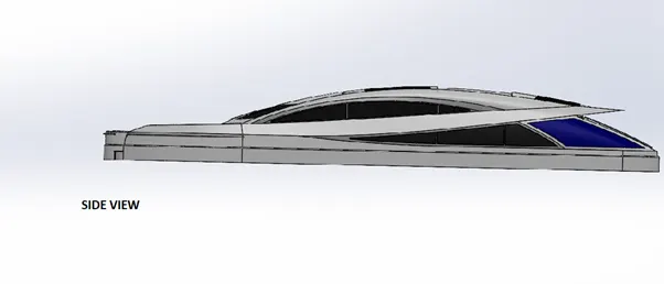
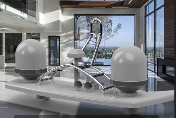
Radar Mast:
A mast system is composed mainly of supporting frames, a C shape base plate, radar transmitter and receiver), and an antenna. This modelled with reference to superstructure top surface. Base plate supports all equipment components over it.
In design of Radar Mast following tools used
Feature tools: -3D sketch, Projected Curve, Boss Extrude, Shell , Chamfer, fillet, Mirror, Dome, Revolve
Sketch tools:-Sketch entities, Trim Entities, Offset Entities, Convert entities.
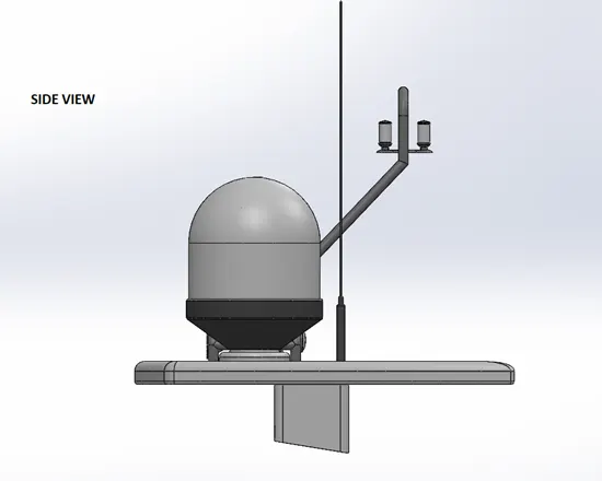
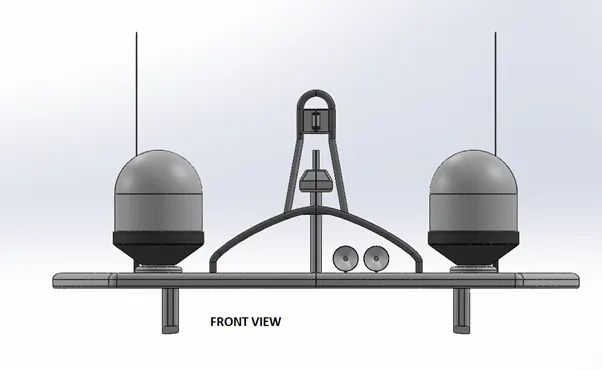
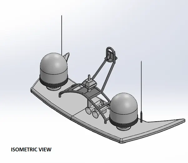
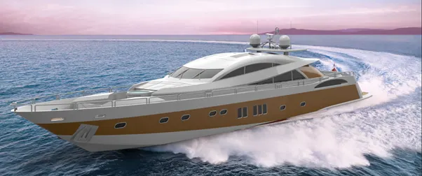
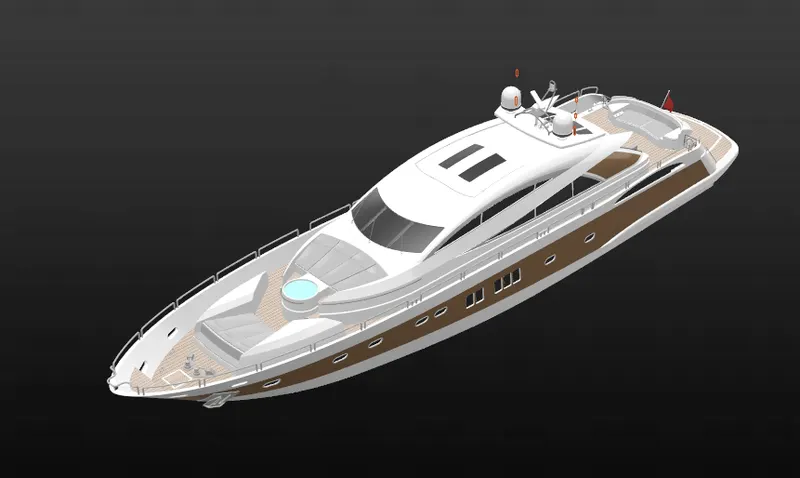
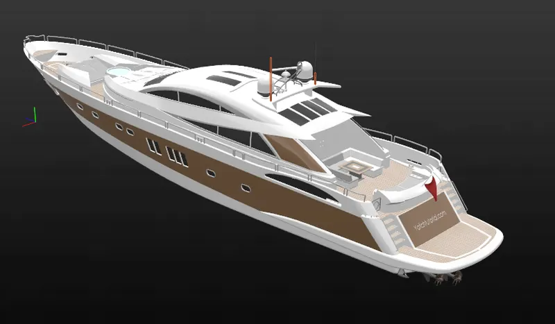
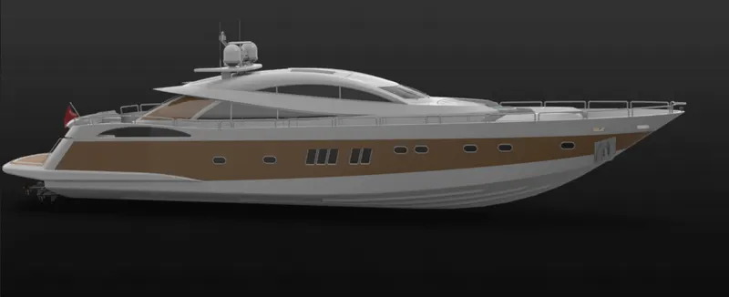
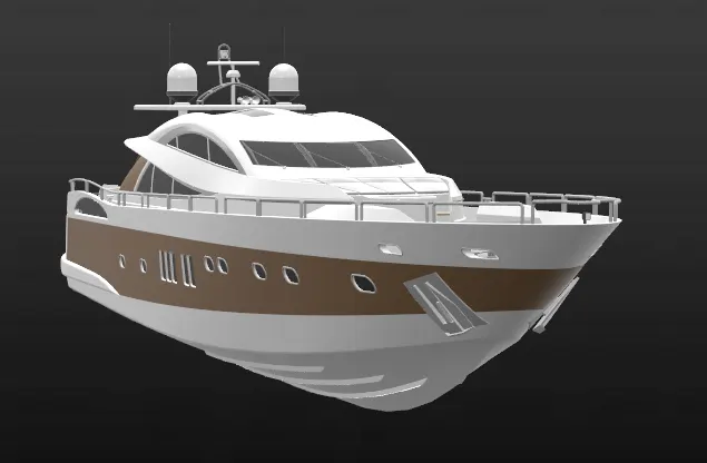
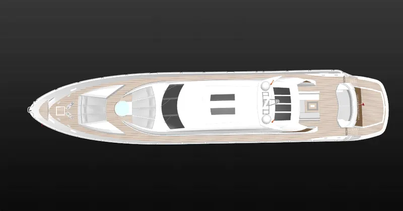
Assembly model
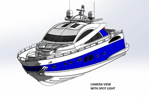
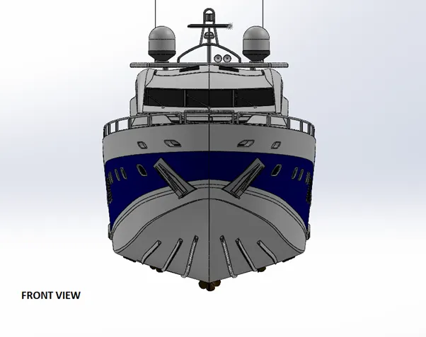
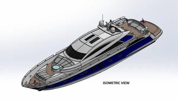
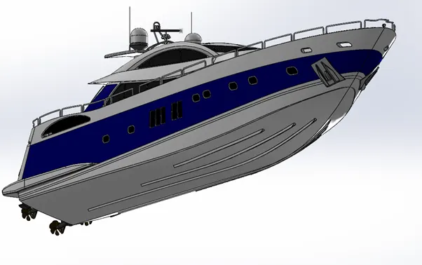
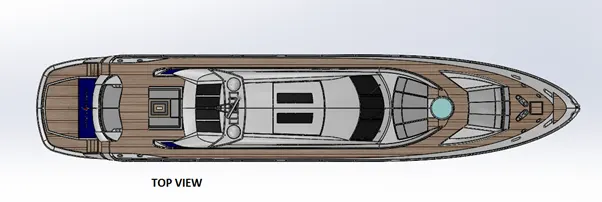
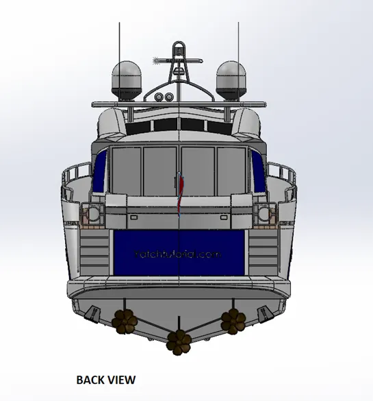
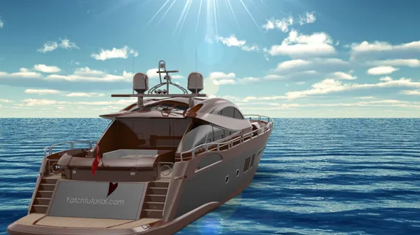
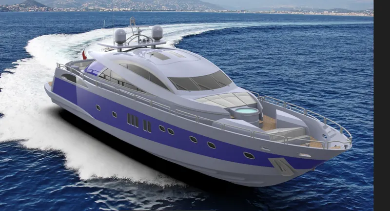
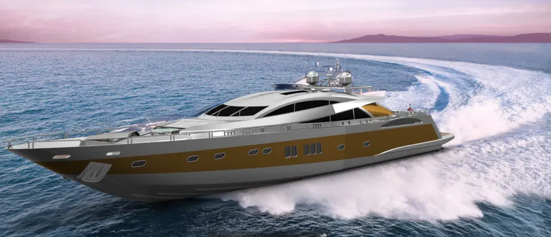
PHOTOREALISTIC RENDERED IMAGES
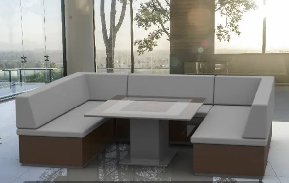
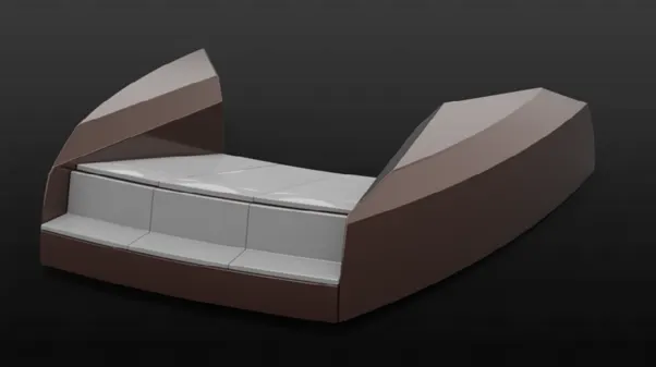
 V
V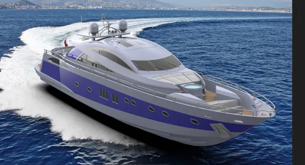
Conclusion-
- We have successfully modelled different parts of yatch with proper dimensions.
- We have successfully assembled all the parts.
- We have successfully rendered all the models and yatch predator.
-------------------------------------------------------------------------------------------------------------------------------------------
RENDERED IMAGES
THANKS AND REGARDS
SUNY KUMAR