Advanced Sheet Metal Design Using NX Cad Challenge_6_Bracket
Report on sheet metal bracket
--------------------------------------------------------------------------------------------------------------------------------------------
DESIGNING SHEET METAL BRACKET IN NX SOFTWARE
Objectives:
- To design sheet metal bracket in nx cad.
- Study about Bead and Holes used in Sheet metal design.
Introduction:
In this report, we are designing the sheet metal part from given drafting of thickness 3mm. Adding bead feature to the part in such a way that its stiffness should increase.
Design methodology
- Drawing the sketch of model with given data on XZ plane
- Using Contour flange command converting sketch into sheet metal of thickness 3mm
- Making normal cut-out to the part to remove unwanted material from model
- using Break corner command adding or removing the sharp corner of model
- Unbending the part to add some more features
- Adding the Bead to the Model to increase it's stiffness.
- Rebending the model
- Adding hole to the model
- Making flat pattern to do the drafting.
.
Description of the tool used.
DATUM PLANE: - It provides an axis on the work base.
SKETCH: - By the help of this tool 2D sketch to be drawn to get the desired shape.
DESIGN PARAMETER: This allows us to set the value of Material Thickness, Relief Depth, Bend Radius, Relief Width, K-Factor.
NORMAL CUTOUT: It allows making holes as per the sketch and removing materials.
BENDING: It allows to bend materials from edges.
COUNTOUR FLANGE: By this tool Created a base feature by extruding along the vector sketch.
UNBEND: It's do flatten bend.
HOLES: It allows to make symmetric standard holes.
DIMPLE: It is used to lift an area in the Closed sketch of the model.
BEAD: It provided to apply stiffness to the surface ( Formed), get oval shape ( Lanced), get oval shape with relief angel ( Punched).
DRAFTING (BASE VIEW): It is used to get detail sketched.
FLANGE: Used to create the flanges of required length and the angle and bend radius.
UNBEND: Used to flatten the sheet metal on give base surface.
BEAD: It is used to create a stamping effect inside or to outside of the sheet metal.
HOLE: It creates a hole of required dia on the selection of the location of the point.
REBEND: It is used to get the sheet metal to its original shape after bending it.
Flat-Pattern: It is used to create a flat surface on the selection of base surface which can be used for the drawings.
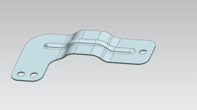
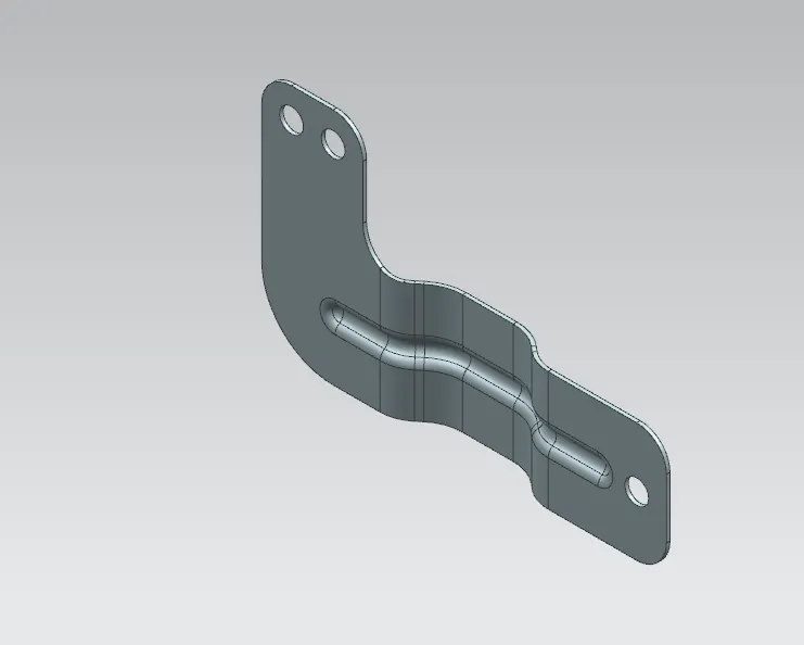
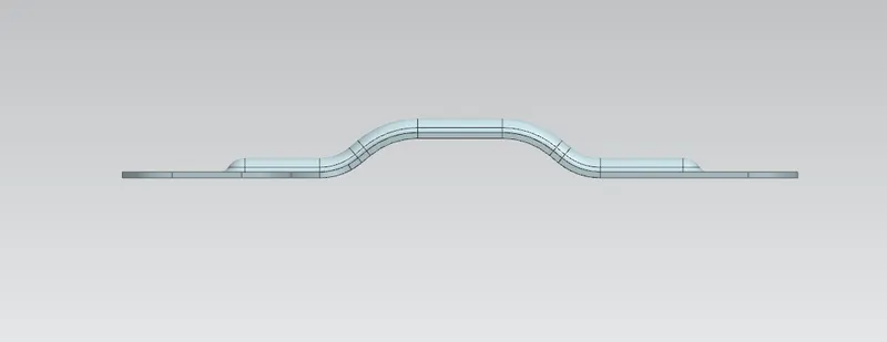
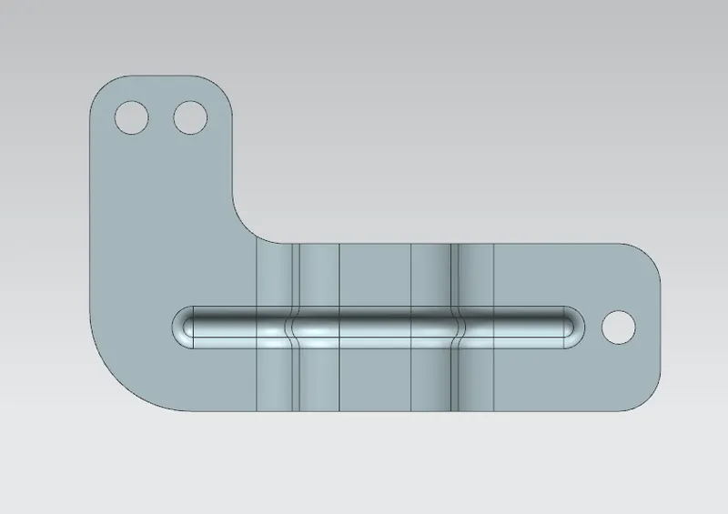
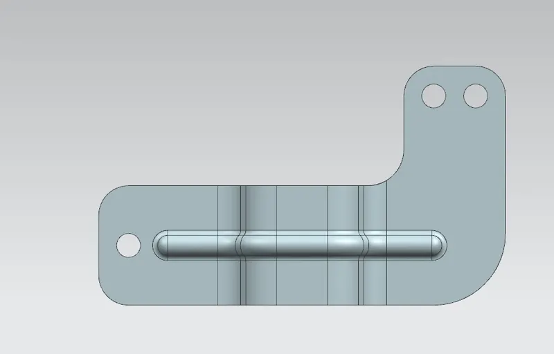
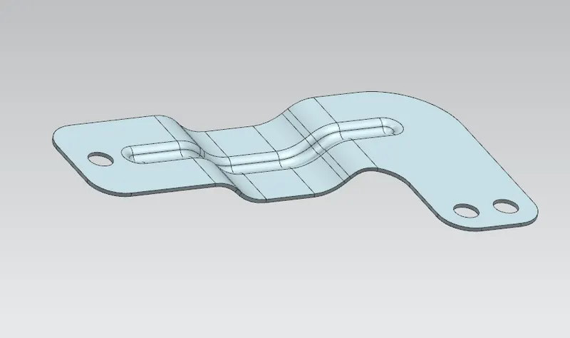
Screenshot of model
DRAWING SHEET IMAGES

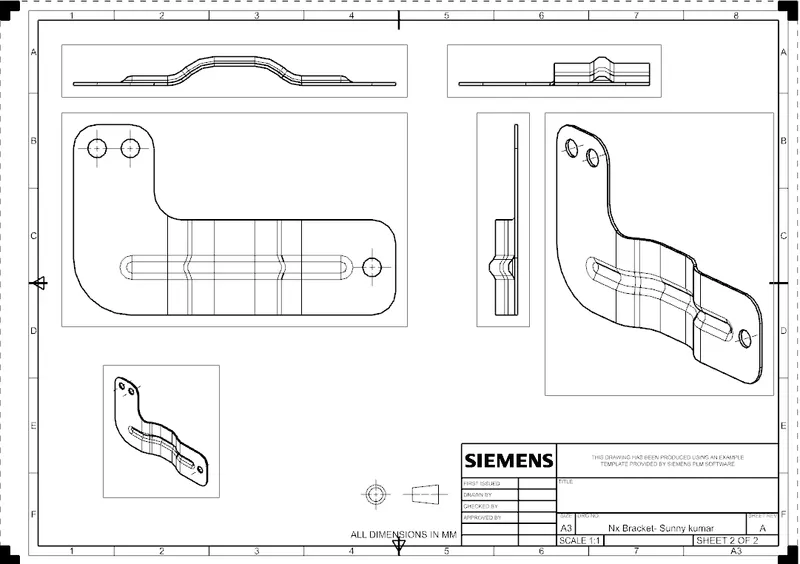
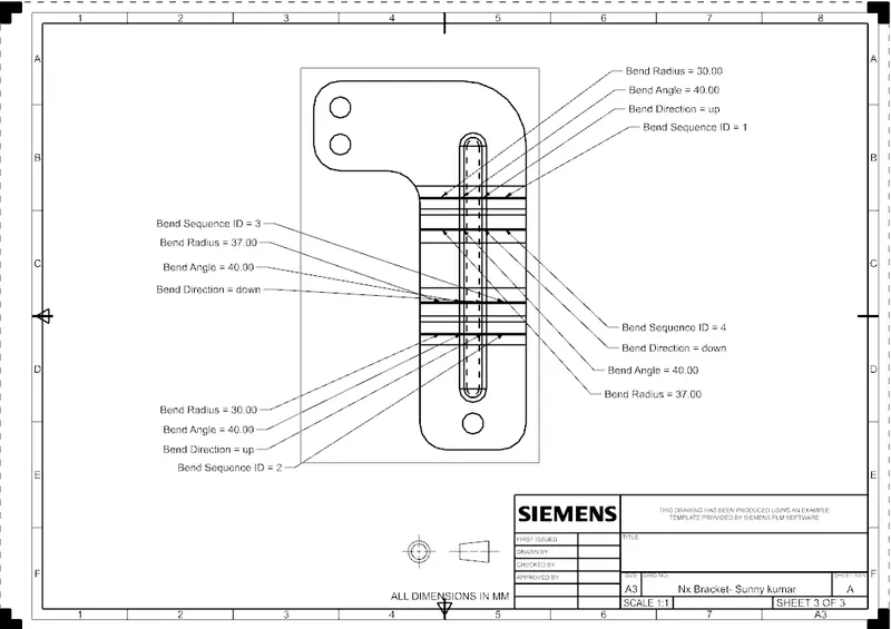
CONCLUSION
WE HAVE SUCCESSFULLY DESIGNED SHEET METAL BRACKET USING NX CAD FAETURES .