Photo Realistic Rendering
Dear Sir
PLease consider my submission.
1.Report on Assembly of Chopper Model.
-------------------------------------------------------------------------------------------------------------------------------------------
AMERICAN CHOPPER (MODELING AND RENDERING IN SOLIDWORKS)
OBJECTIVE
To get familiarize with solidworks.
- Sketching and modelling of different parts of the American chopper.
- Assembly of all the parts of American chopper.
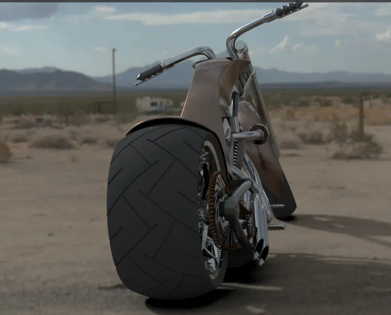
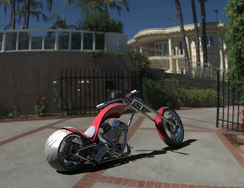
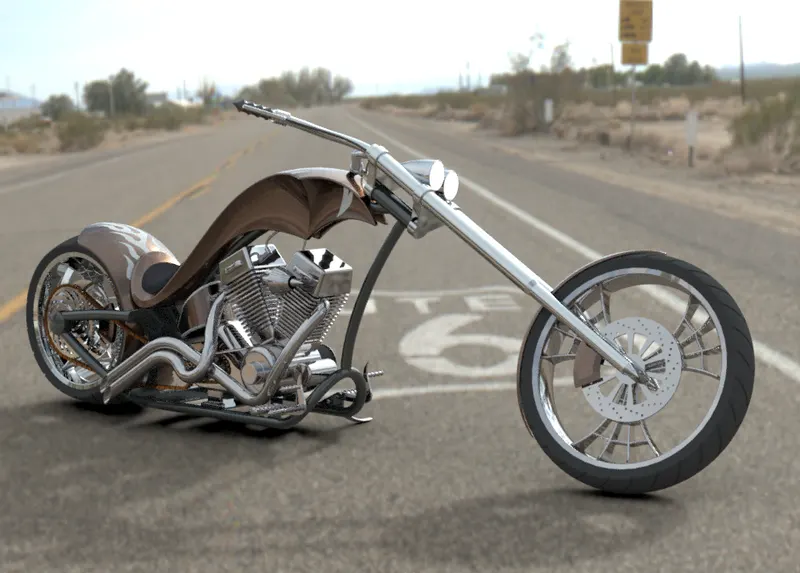
- Photorealistic rendering of American chopper.
INTRODUCTION
The days of drafting with pencil, paper, and protractors are winding down as most engineers, PCB designers, and architects become experts at using CAD (computer-aided design) software. CAD is software specifically created to help draft documentation, visualize 2D or 3D design concepts using photorealistic renderings, simulate real-world functionality, and export CAD data to computer-aided manufacturing (CAM) software.
Product development is a very complex process because modern products are more elaborate since there is a demand of maximum efficiency with minimal consumption of certain means.
The development in the automotive industry follows this trend. The use of various modern software such as CAD and CAE technologies, enables us to perform various researches very effectively and efficiently, and it is possible to test different modifications in order to improve the characteristics and develop them.
The benefits of these systems are that they enable faster and cheaper research and development of vehicle. Through this project I got familiarize with one of the CAD software called Solidworks, through modelling an American chopper. A chopper is a type of custom motorcycle. The chopper is perhaps the most extreme of all custom styles, often using radically modified steering angles and lengthened forks for a stretched-out appearance. Here we go through different stages like part modeling, assembly and do a photo realistic rendering of an American Chopper.
DESIGN METHODOLOGY FLOWCHART
AMERICAN CHOPPER
1. 2. 3.
PART MODELING ASSEMBLY OF PARTS SCENE RENDERING
CHASSIS CREATING MATES APPEARANCES
ENGINE LIGHTS
FRONT WHEEL CAMERAS
FRONT FENDER BACKGROND SCENES
FRONT FORK
REAR WHEEL
REAR FENDER
OIL TANK
GAS TANK
CHAIN
PEDAL
TRANSMISSION BELT
KICK STAND
DESCRIPTIONS OF THE FEATURES AND TOOLS USED
- 2d sketch: 2d sketch is the basic command which takes one to the sketching template. It is here where we make the sketches required to make solid body or part. We have to select a plane from 3 predefined planes namely Front Plane, Top Plane and Right plane.
- 3d sketch: In 3d sketch, we make a sketch in a 3dimensional space rather than in a 2dimensional plane.
- Splines: The SOLIDWORKS software supports two types of splines, B-splines and style splines. You can use B-splines to create complex curves. You can define and modify them using several controls, including spline points, spline handles, and control polygons. A single B-spline can have multiple through points and spans (the region between through points). You can apply curvature constraints at each endpoint. At each point, you can weigh the tangency vector and control the tangency direction.
- Sketch Fillet: The Sketch Fillet tool trims away the corner at the intersection of two sketch entities to create a tangent arc. This tool is available for both 2D and 3D sketches. The Fillet tool on the Features toolbar fillets entities such as edges in parts. The two corners of the rectangle are filleted with the same radius and with Keep constrained corners selected.
- Ellipse: The Ellipse tool to create a complete ellipse. Use the Partial Ellipse tool to create an elliptical arc.
- Fillets: Fillet/Round creates a rounded internal or external face on the part. You can fillet all edges of a face, selected sets of faces, selected edges, or edge loops.
- Sketch Fillets: The Sketch Fillet tool trims away the corner at the intersection of two sketch entities to create a tangent arc. This tool is available for both 2D and 3D sketches. The Fillet tool on the Features toolbar fillets entities such as edges in parts. The two corners of the rectangle are filleted with the same radius and with Keep constrained corners selected.
- Boss Extrude: creates a solid based on the sketch.
- Cut Extrude: make a cut out of the existing solid body.
- Revolve Boss: evolves add or remove material by revolving one or more profiles around a centreline. You can create revolved boss/bases, cuts, or revolved surfaces. The revolve feature can be a solid, a thin feature, or a surface. The sketch must a 2d sketch not a 3d sketch. Axis of revolution can be 3d sketch.
- Revolve Cut: does a cut w.r.t an axis of rotation according to sketch made.
- Sweeps: Sweep creates a base, boss, cut, or surface by moving a profile (section) along a path. A sweep can be simple or complex. To generate the swept geometry, the software creates a series of intermediate sections made by replicating a profile at various positions along the path. The intermediate sections are then blended together. Additional parameters can be included in the sweep feature such as guide curves, profile orientation options, and twist to create a wide variety of shapes.
- Loft: Loft creates a feature by making transitions between profiles. A loft can be a base, boss, cut, or surface. You create a loft using two or more profiles. Only the first, last, or first and last profiles can be points. All sketch entities, including guide curves and profiles, can be contained in a single 3D sketch.
- Chamfer: The chamfer tool creates a bevelled feature on selected edges, faces, or a vertex.
- Shell: The shell tool hollows out a part, leaves open the faces you select, and creates thin-walled features on the remaining faces. If you do not select any face on the model, you can shell a solid part, creating a closed, hollow model. You can also shell a model using multiple thicknesses.
- Dome: Creates a dome on the face selected.
- Linear Pattern: The Linear Pattern Property Manager appears when you pattern one or more features along one or two linear paths.
- Circular Pattern: The Circular Pattern Property Manager appears when you pattern one or more features around an axis.
- Sketch Driven Pattern: Using sketch points within a sketch, you can specify a feature pattern. The seed feature propagates throughout the pattern to each point in the sketch. You can use sketch driven patterns for holes or other feature instances.
- Split: You can split a sketch entity to create two sketch entities. Conversely, you can delete a split point to combine two sketch entities into a single sketch entity. Use two split points to split a circle, full ellipse, or a closed spline.
- Project Curve: The project curve will be available under the feature tab. The project curves command can be used to create a 3D curve. The 3D curve can be created by using the reference of two 2D curves.
- Extend: You can add to the length of a sketch entity (line, centreline, or arc). Use Extend Entities to extend a sketch entity to meet another sketch entity.
- Convert Entities: You can create one or more curves in a sketch by projecting an edge, loop, face, curve, or external sketch contour, set of edges, or set of sketch curves onto the sketch plane.
- Trim: Select the trim type based on the entities you want to trim or extend. All trim types are available with 2D sketches and 2D sketches on 3D planes.
- Mirror: Select Mirror Entities to mirror pre-existing 2D sketch entities on a plane, and then select the entity about which to mirror. If you want to first select the entity about which to mirror, and then sketch the entities to mirror, select Dynamic Mirror Entities.
- Sketch Picture: Sketch pictures are used as a reference to draw sketches.
- Sketch Pattern: Create linear or circular sketch patterns using elements from sketch entities you intend to pattern or model edges.
- Dynamic Mirror Sketch Entities: Select the Dynamic Mirror Entities tool to first select the entity about which to mirror, and then sketch the entities to mirror.
Part images Features and Tools used
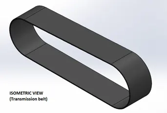 |
Transmission belt
· Sketch · Offset · Extrude · Fillet · Appearances ……………………….. |
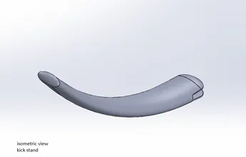 |
Kick stand· 2d sketch · Ellipse · Spline · Pierce · Loft · Cut extrude · Boss extrude · split |
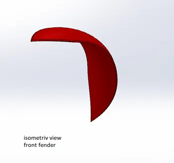 |
Front fender· 2d sketch · 3-point arc · Offset · Extend · Trim · Revolve · Spline · fillet |
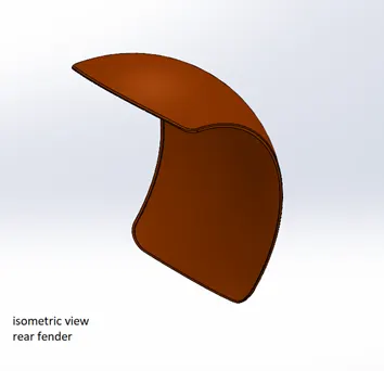 |
Rear fender· 2d sketch · 3-point arc · Extend · Trim · Revolve · Spline · Fillet · shell |
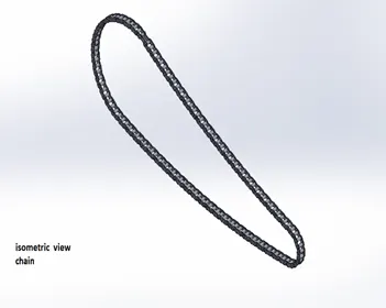 |
Chain· 2d sketch · Circles · 3point arc · Slot · Blocks · Fillet · Curve pattern · mirror |
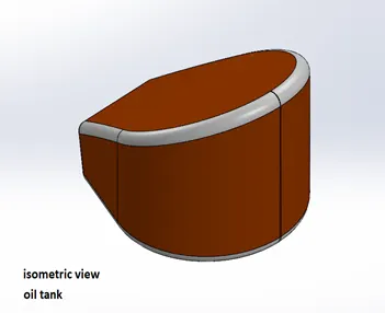 |
Oil tank· Lines · 3point arc · Boss extrude · Combine · Fillet · shell |
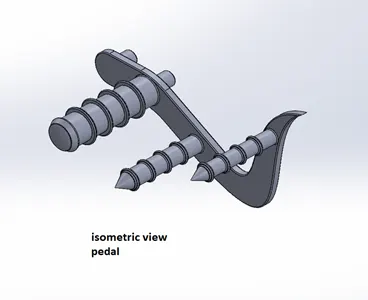 |
Pedal· 2d sketch · Lines · Circles · Fillets · Revolve · Dome · Chamfer · Linear pattern |
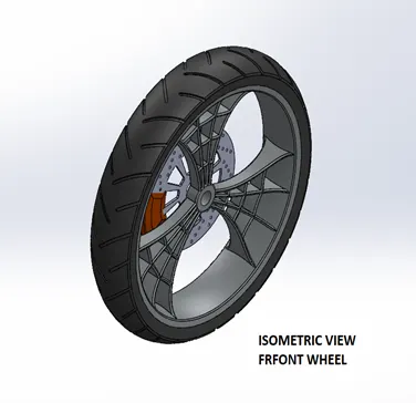 |
Front wheel· 2d sketch · Straight lines · 3-point arc · Sketch fillet · Revolve · Spline · Extend · Trim · Cut extrude · Offset · Cut revolve · Circular pattern · Chamfer · Fillet · Corner point rectangle |
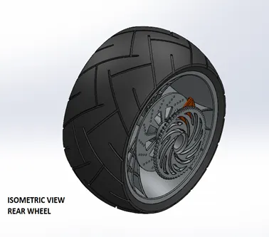 |
Rear wheel· 2d sketch · Straight lines · 3point arc · Sketch fillet · Revolve · Spline · Extend · Trim · Cut extrude · Offset · Cut revolve · Circular pattern · Chamfer · Fillet · Corner centre point rectangle |
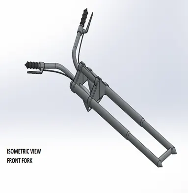 |
Front fork· 2d sketch · Straight lines · Revolve · Circle · Fillets · Linear pattern · Spline · Cut extrude · Dome · Move body · Curve · Sweep · Plane · Mirror · Combine |
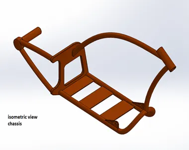 |
Chassis· Sketch pictures · Splines · Curves · Mirror · Boss extrude · Cut extrude · Chamfer · Dome · Split · Revolve · combine |
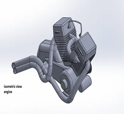 |
Engine2d sketch Sketch picture Straight lines Circles Boss extrude Fillet Revolve Plane Dome Circular pattern Chamfer Mirror Cut extrude Combine Mirror Composite curve split |
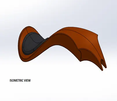 |
Gas tank· 2d sketch · Spline · Surface sweep · Surface trim · Surface boundary · Surface loft · Curve · Mirror · Surface knit · Surface extrude · Fillet · Cut extrude · shell |
ASSEMBLY MODEL
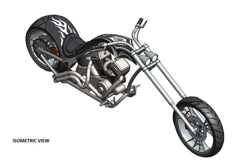
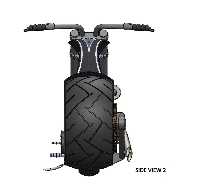
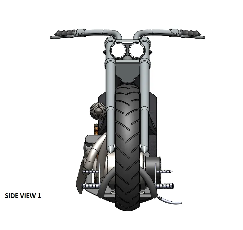
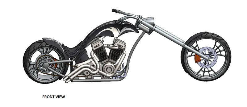
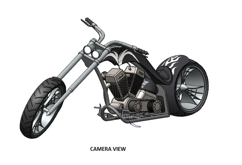
RENDERED IMAGES OF FEW PARTS-
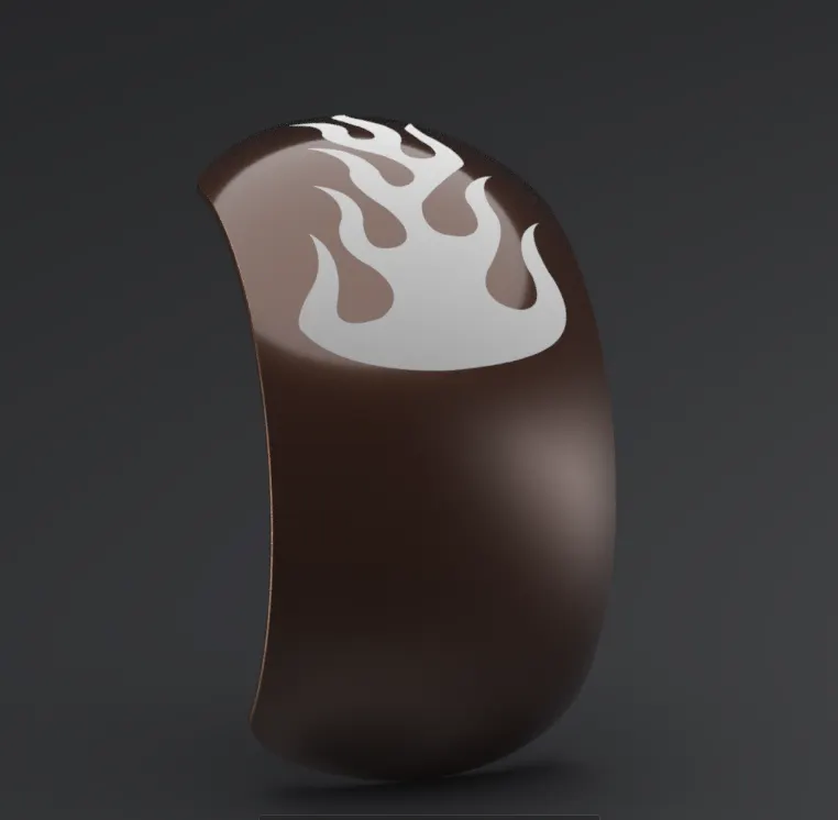
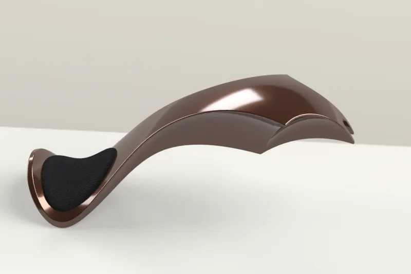
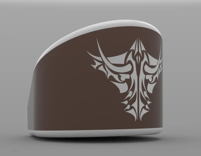
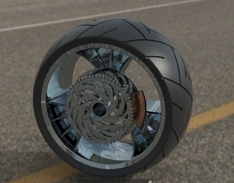
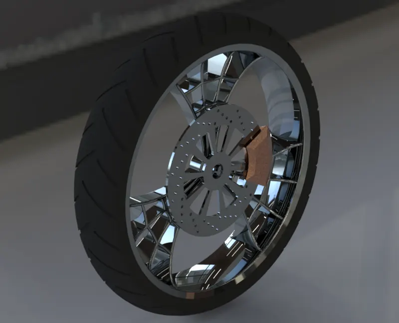
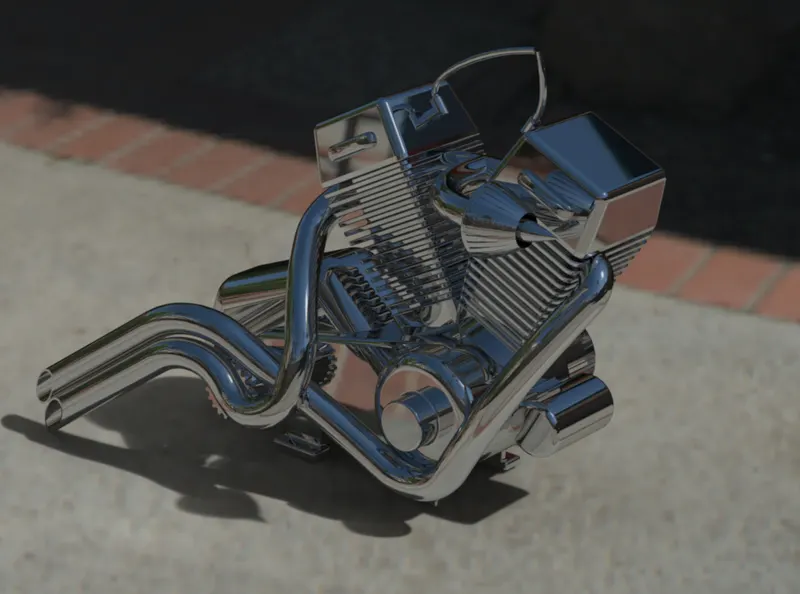
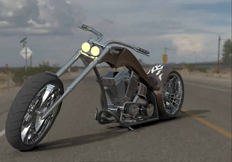
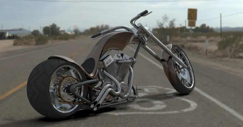
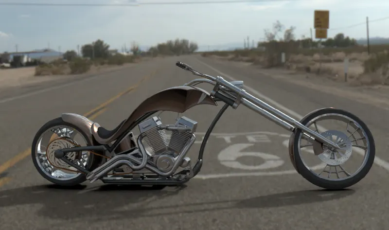
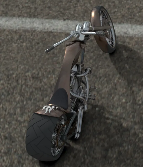
RENDERED IMAGES OF AMERICAN CHOPPER
CONCLUSION-
- Modelled different parts of chopper using solidworks.
- Assembled the chopper using proper mates.
- Applied decals,lights,cameras and enviroments.
- rendered the model using diffrent views.
-------------------------------------------------------------------------------------------------------------------------------------------
3. IMAGES OF RENDERS
THANKS AND REGARDS
SUNNY KUMAR