Advanced Sheet Metal Design Using NX Cad Challenge_2_Box Assembly
REPORT ON BOX ASSEMBLY
-------------------------------------------------------------------------------------------------------------------------------------------
BOX ASSEMBLY USING NX CAD
Objective:
To learn and implement the principles of Advanced Sheet Metal design using NX CAD as a tool.
To understand Sheet Metal applications and its importance as per industry standards.
Introduction:
Sheet metal is any metal that has a thickness in between 0.5 mm and 6 mm. Any metal piece thicker than 6mm are considered as Structural Metal (for ex. Structural Steel) and any metal piece having thickness lower than 0.2mm is called Metal Foil.
Sheet metal is one of the fundamental forms used in metalworking, and it can be cut and bent into a variety of shapes.
It is found in various industrial application ranging from small and light Fixture to an Automotive Body Part. Sheet metal applications have wide range due to its properties like: High Strength, Low weight and Corrosion Resistance.
General Sheet Metal materials are Steel, Aluminium, Brass, Titanium. There are 2 ways of producing Sheet Metal – Hot Rolling and Cold Rolling. For precision applications, cold rolled steels are preferred as manufacturers have more control over the final dimensions. This is because in hot rolled steels, after cooling, the steel shrinks slightly and the shape might change a little.
Design methodology for Modelling of Box Assembly
- Start NX 12 and create new sheet metal model
- Create tab and add flange and hem
- Use mirror feature to mirror the body
- Add Dimple -use mirror feature
- Unbend the metal sheet
- Add bead and use mirror feature
- Add hem flange at the side edges
- Create new Datum plane and create new sketch
- Use tab feature to create lid and add flanges
- Create tab, add flanges, hem & use break corner
- Unbend the newly created sheet Draw sketch,
- use Normal Cut-out, Rebend & mirror,
- create new tab, flanges and hem
- add normal cut-out and rebend
- apply colours to different parts.
Description of the Features
Sketch: It is the basic feature for the any kind of operation.
Tab: a base feature by extruding a sketch along a vector by a thickness value or adds a material to a plane face
Normal Cut-out: Cuts the model perpendicular to the sketch
Bend: Modifies the model by bending material on one side of a sketch line adding a bend between the two sides
Break Corner: Rounds a sharp corner
Unbend: Flattens a bend
Hole: Create a hole with the circle created
Bead: Lifts a material along a counter of sketch that simulates stamping a tool.
Mirror: Used to create a same feature respect to the plane or sketch
Dimple: Lifts an area of the model inside a sketch that simulates stamping a tool.
Rebend: Restores a bend Drafting: It is the creation of drawing for the purposes of determining how the device should be created.
PROCEDURE
- Create a base and then use flanges on two ends normal to xy plane using the dimensions given and then make flanges on right ends of the part normal to xz. Use close corners to cover the gaps between the flanges and base
- Close the gap between flanges by using hem flange with bend radius O and bend length 0.02. Mirror the component and then unite the component to make a body without a cover
- Make all beads and dimples on the base and side of the box, then mirror them and create a cover on the box
- To make the hinges connecting the cover and the box, create a tab on the flange and cut the unwanted parts. bend the tab 360degrees. Repeat the same step for the cover and mirror them.
- Change the colour of each part and save it as part
SCREENSHOTS OF THE MODEL
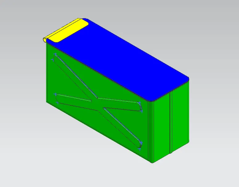
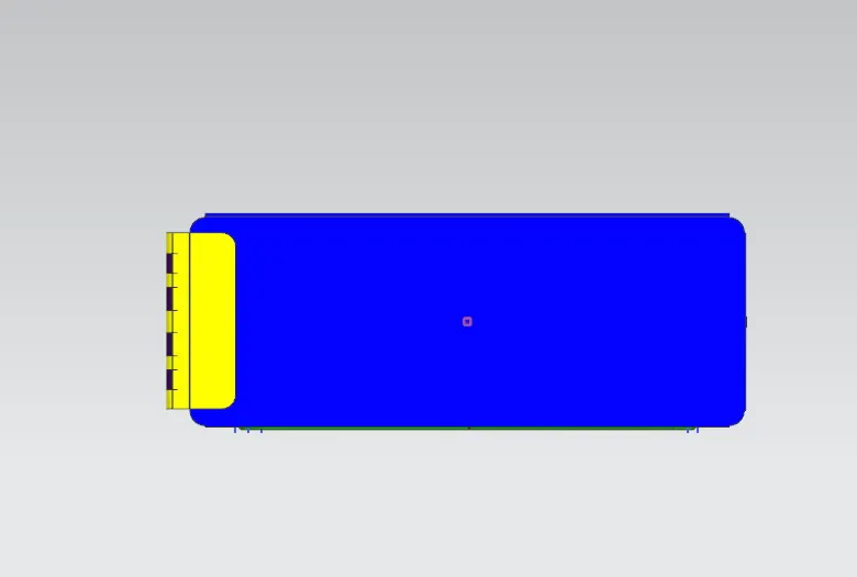
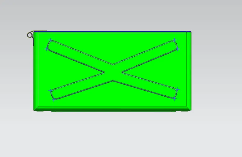
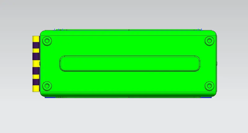
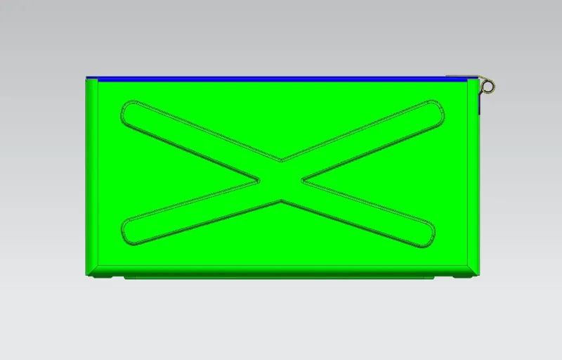
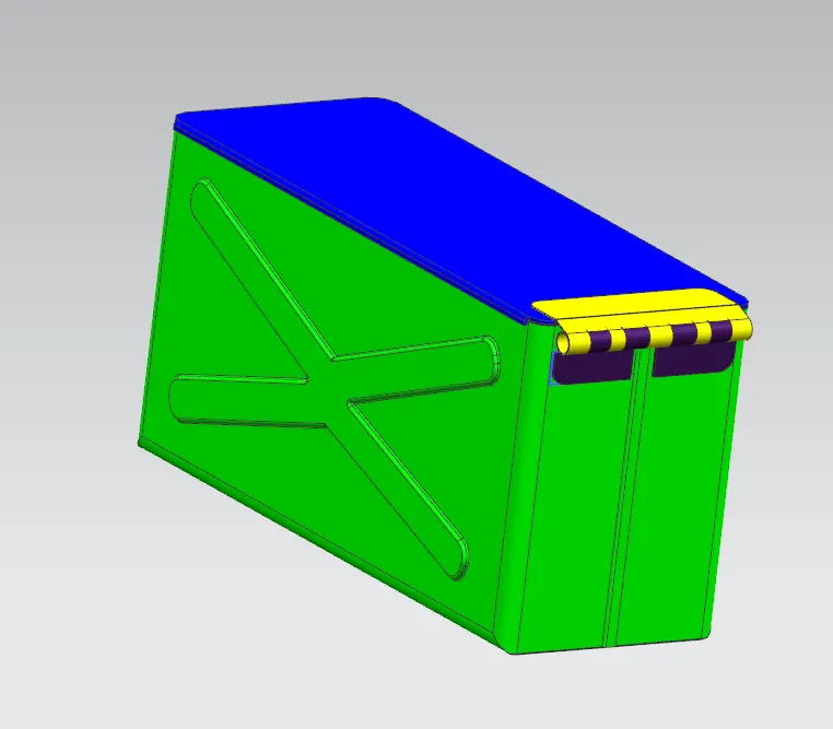
DRAWING SHEET IMAGE
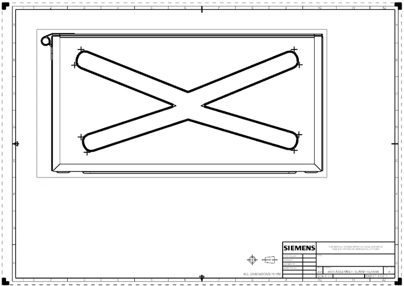
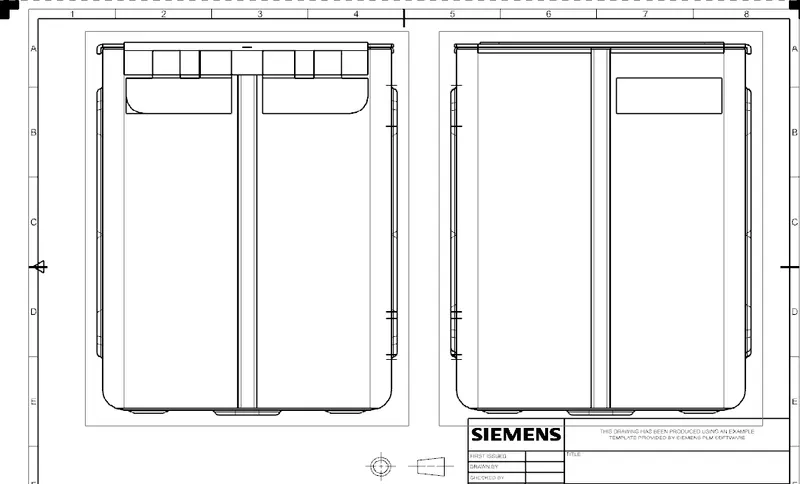
CONCLUSION
We have learned how to model box assembly using different features in nx cad .