Proportional Valve simulation
PROPORTIONAL VALVE SIMULATION
AIM:
To run the simulation for proportional valve with 3 different lifts using with and without Adaptive Mesh Refinement.
OBJECTIVE:
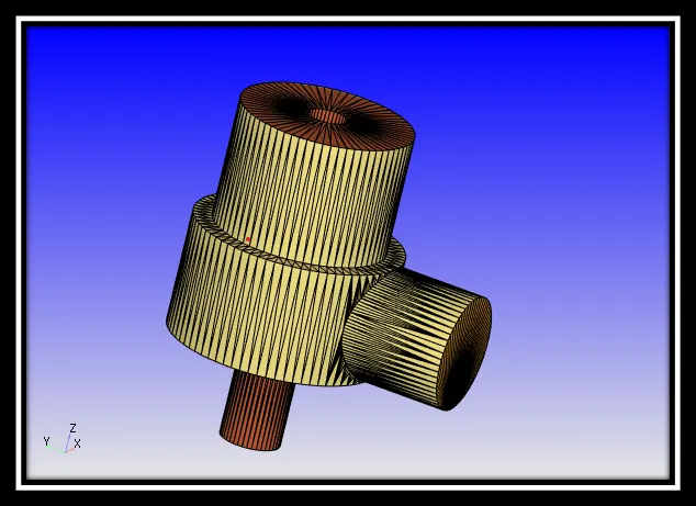
A proportional control valve is a valve used to control fluid flow rate by varying the size of the flow passage via a restrictor. The regulated flow rate subsequently adjusts parameters affecting a process in a system, mainly level, pressure and temperature.
In an automated control valve, the restricted is directed by a signal from a controller called an actuator. A proportional control solenoid valve utilizes a solenoid as an actuator for variable valve positioning.
A direct operated 2-way standard proportional solenoid valve operates very similar to a direct-operated valve with the difference that the former operates through the range of valve positioning while the later only provides two switching states (i.e. on/off).
In principle it is possible to proportionally control the plunger with variable DC voltage, however in practice state friction on the guide points of the plunger impairs the sensitivity of the valve, which results in greater hysteresis effects. To prevent static friction, the normal inlet signal can be converted into pulse width modulated voltage signal (PWM) using special control electronics.
Pulse-width modulation (PWM) is a technique often used to allow the control of the power supplied to electrical devices. The average value of voltage fed to the solenoid is controlled by turning the power switch on and off. This kind of control puts the plunger into a very fast but weak amplitude oscillation. The oscillation puts the plunger in a balanced state which maintains its constant sliding friction. The plunger’s oscillation motion has no effect on the fluid flow behaviour.
CASE SETUP:
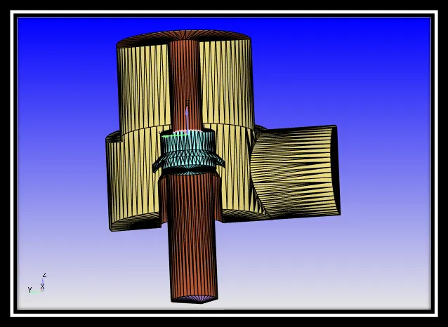
For the simulation process, air is selected for the flow. In the run parameters the solver is selected as steady state solver and the simulation mode will be in full hydrodynamic. In solver parameters, The Navier-Strokes solver type will be in density based.
In simulation time parameters:
End time: 15000 cycles
Initial time-step: 1e-09 sec
Min time-step: 1e-09 sec
Max time-step: 1.0 sec
In boundary condition:
Inlet (BOUNDAY ID-4): Pressure- 3000000.0 Pa
Velocity- Zero Gradient
Temperature- 300 K
Outlet (BOUNDARY ID-3): Pressure- 101325 Pa
Velocity- Zero Gradient
Temperature- 300 K
Wall Inlet: Wall motion type- Stationary
Surface movement- FIXED
Temperature- Zero Gradient
Wall Casing: Wall motion type- Stationary
Surface movement- FIXED
Temperature- Zero Gradient
Valve spindle: Wall motion type- Stationary
Surface movement- FIXED
Temperature- Zero Gradient
In grid control:
Base grid: 0.004m
In terms of ADAPTIVE MESH REFINEMENT:
Adaptive Mesh Refinement: Cycle steady- 100
Min cells- 1
Max cells- 2000
Embed frequency- 1
Release frequency- 25
Here, velocity is selected.
Embed type- Sub grid scale
Max embedding level- 3
Sub-grid criterion- 1.0 m/s
Timing control type- SEQUENTIAL
Start- 4000 cycles
End- 15000 cycles
In terms of not using ADAPTIVE MESH REFINEMENT and running the case with FSI:
In simulation parameters:
Body forces: X direction- 0
Y direction- 0
Z direction- (-9.81)
In boundary condition:
Inlet (BOUNDAY ID-4):
Pressure- Profile type- Temporal
Type- SEQUENTIAL
|
SECONDS |
PRESSURE(Pa) |
|
0.1 |
3068750.0 |
|
0.2 |
3087500.0 |
|
0.3 |
3106250.0 |
|
0.4 |
3125000.0 |
|
0.5 |
3143750.0 |
|
0.6 |
3162500.0 |
|
0.7 |
3181250.0 |
|
0.8 |
3200000.0 |
|
0.9 |
3218750.0 |
|
1.0 |
3237500.0 |
|
1.5 |
101325.0 |
Valve spindle: Wall motion type- FSI
Temperature- Zero Gradient
In physical models:
The type is selected as rigid under the name Rigid_FSI_1. Valve spindle is selected as boundaries. Under the parameters,
Start time- (-999999.0) cycle
Centre of mass flag- Use geometric centre (constant density)
Mass flag- 3.1 kg
Under forces/moments
Constant applied force- (-7126.0) N
Under constrained motion
Min displacement- (-1e-38) m
Max displacement- 0.1 m
The rest of the case setup is similar for both the process.
Surface with edges:
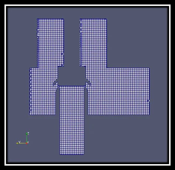
MESH-3mm (with and without AMR):
Pressure contours:
With AMR: https://www.youtube.com/watch?v=JjePgwJ_fp8
Without AMR: https://www.youtube.com/watch?v=29We4cyXQ_Q
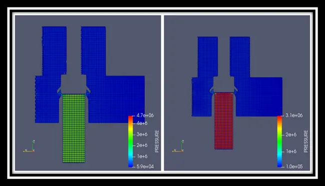
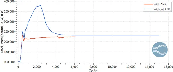
From the above both images we can see that, when air enters through the inlet it pushes the valve against the spring force and went outside through the outlet. After some moment, due to the spring force the valve is being pushed back which makes the pressure rise at a particular point.
Velocity contours:
With AMR: https://www.youtube.com/watch?v=RR-JR9Orupw&feature=youtu.be
Without AMR: https://www.youtube.com/watch?v=PSLHAHBKJl8&feature=youtu.be
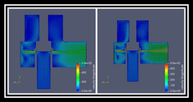
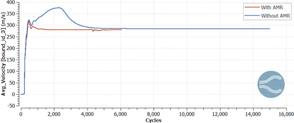
When the air enters, due to the high velocity it pushes the valve and the air gets scattered as it flow into it and therefore the velocity gets reduced and comes back to zero when pressure is at high point.
MESH- 4mm (with and without AMR):
Pressure contours:
With AMR: https://www.youtube.com/watch?v=wdqcILvNcgU&feature=youtu.be
Without AMR: https://www.youtube.com/watch?v=5_jmqOHbQjM&feature=youtu.be
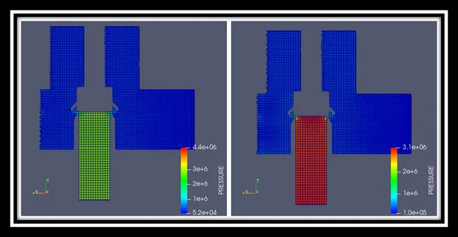
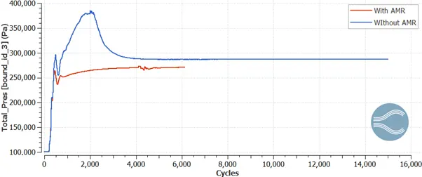
Here the spindle valve is lifted to 1mm higher than the previous position which reduces the maximum level of pressure.
Velocity contours:
With AMR: https://www.youtube.com/watch?v=42O87MzH-v0&feature=youtu.be
Without AMR: https://www.youtube.com/watch?v=7ZhSymKXLoU&feature=youtu.be
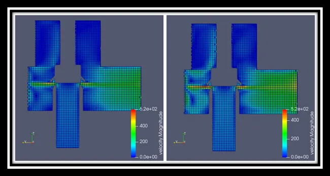
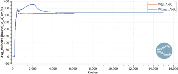
Here in this position of valve, the velocity is even higher than when it is compared to the previous one because of increase in space between inlet and valve spindle.
MESH- 5mm (with and without AMR):
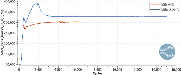
Pressure contours:
With AMR: https://www.youtube.com/watch?v=pkUcqMkueXc&feature=youtu.be
Without AMR: https://www.youtube.com/watch?v=396IMriSPYk&feature=youtu.be
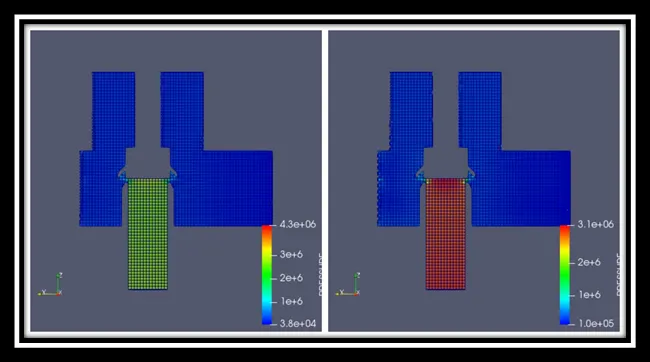
Here the spindle valve is lifted to 1mm higher than the previous position which reduces the maximum level of pressure.
Velocity contours:
With AMR: https://www.youtube.com/watch?v=v87GmKBU_xs&feature=youtu.be
Without AMR: https://www.youtube.com/watch?v=ux5UJfNkpJ0&feature=youtu.be
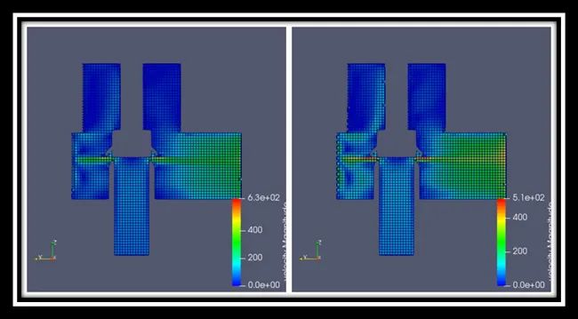
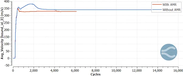
Here in this position of valve, the velocity is even higher than when it is compared to the previous one because of increase in space between inlet and valve spindle.
Mass flow rate:
With AMR:
Without AMR:
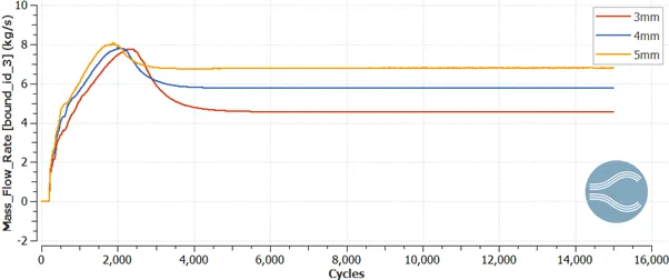
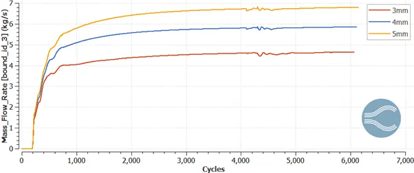
From the above graph, it is clear that as the lift increases the mass flow rate also increases with respect to both the situation of using AMR and not using AMR.
CONCLUSION:
So, the simulation of proportional valve with 3 different lifts of spindle valve by using AMR and without using AMR along with FSI model is done.