Project - Speed Control of a Direct Current (DC) motor
MATHEMATICAL MODELING OF DC MOTOR
A DC motor is an electrical machine that converts electrical energy into mechanical energy. In a DC motor, the input electrical energy is the direct current which is transformed into mechanical rotation.
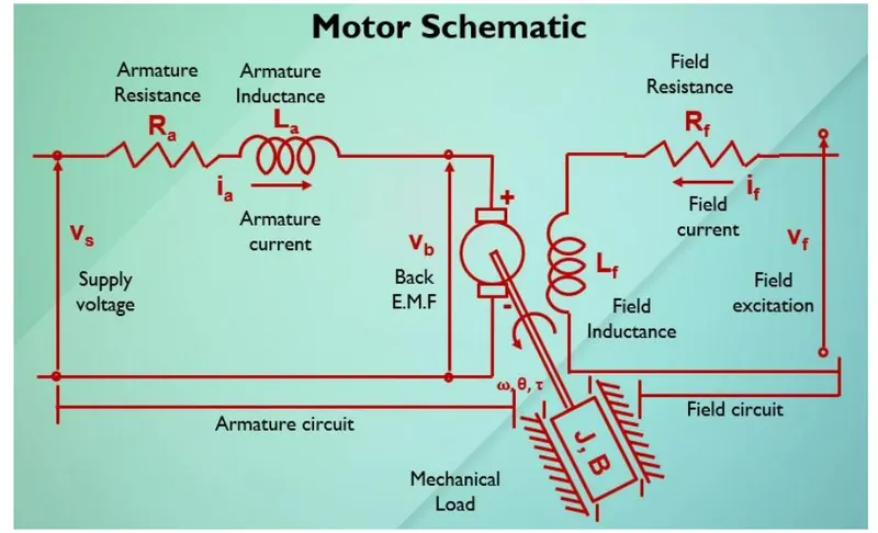
DC motor consists of a stator and rotor, the stator of the motor is the permanent magnet in the small dc machine, and electro-magnets in the large motors, and the rotor of the machine is a simple coil that rotates due to the Lorentz law, the armature is connected to dc power through pair of commutator rings when the current flows in the coil which is in magnet field an electromotive force induced in it according to Laurent law
the power to these electromagnets is given from the same DC source of the armature if the field is connected in series to the armature then the motor is known as a series motor and if the field is connected across the armature then the motor is said to be a shunt motor
LET:
J =MOMENT OF INERTIA OF A MOTOR=
B=MOTOR VISCOUS FRICTION=
L=ARMATURE INDUCTANCE=
Vb =back emf
Kt=motor torque constant=
Km=back emf constant=
R=armature resistance=
For this above schematic Diagram ,we will assume the Input odf the dc moter is Voltage source(Vs) and out of the moter is Rotational speed (w) of the moter shaft.
>>Both the rotor and shaft are to rigid then we gets the Viscus friction(J) and Tarque(T).
>> The Tarque (T) of the motor is prapotional to the armature Current (ia) with tarque Constant (Kt)
i.e., T=Kt * ia-----------(1)
>> Back EMF (Vb) is praportional to angular velocity (theta_dot) by a praportional constatnt (Kb)
i,e., Vb = Kb * (theta_dot)----------(2)
>>For creating the The SIMULINK MODEL of above given DC moter let us find the transfer funcion as followes ::-
From the schematic diagram we have apply kirchoff's Voltage law To the Armature Circuit as Given below:-
Armature Circuit Equatation Part :-
Vs= Ra* ia + L (dia/ dt) +Vb ----------(3)
substitute eqn (2) in eqn (3) then we get
Vs= Ra* ia + L (dia/ dt) +(Kb* (theta_dot)-----------(4)
Vs-(Kb* (theta_dot)=Ra* ia + L (dia/ dt)------------(5)
From Equatation (5) we can write as :-
L( d ia / dt ) = (Vs-(Kb* (theta_dot)-Ra*ia)-----------(6)
Field Circuit Equatation Part:-
Appling the Newton's Law of Moton for Field circuit Then we get:-
J(d^2 theta /d t^2) + B (d theta /d t)= Kt * ia---------------(7)
Aplly Laplace Transforms to both equatations (6) and (7) then :-
from eqn (6) :-
L I(S)=V(S)- Kb (theta (S)- Ra I(S)
L I(S)+ Ra I(S)=V(S)- Kb (theta (S)
I(S) (L+Ra)=V(S)- Kb (theta (S)
I(S)=V(S)- Kb (theta (S) / (L+Ra)-----------------(8)
From eqn (7):-
J S^2 (theta (S))+ B s (theta (S)) =kt * I(S)---------------(9)
substitute I(S) value in eqn (9) then we get :-
J S^2 (theta (S))+ B s (theta (S)) =kt *{V(S)- Kb (theta (S) / (L+Ra)}
S * theta (S) ( J S +B)=kt *{V(S)- Kb (theta (S) / (L S+Ra)}---------------------(10)
From equatation (10) We get transfer function between output (w(s)) Angular velocity and input volatge (Vs) as followes :-
W(S) / Vs = Kt / {(L S+Ra) (J S + B)+Kt* Kb}-----------------(11)
Design_parameters for Subsystem:-
PROCEDURE :-
For Creating This model ,
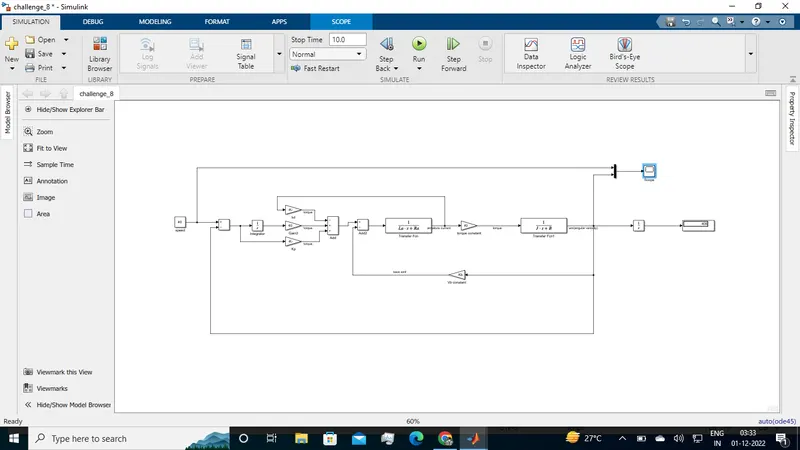
i)firstly we created the Two transfor functions one is ''armature part'' and seconf one is related to moment of inertia and friction constant
ii)Now we are subtracting the Source voltage from back EMF (Vb) by using the sum block.
and this is added to the input signal as Armature Transfer function
iii0After We are creating the tarque BY using gain and armature transfer Function we can obser this in above Model.
iv) After this can uses to produe the Speed of DC moter By usinhg inertia and friction constant as shown in above block.
v)We can give the In1 and OUt1 as to know the input signals and Output signals respectively.
From Above steps we can get the Mathematical Model Of DC moter (Fig-1).
THis Entire All blocks cen be converted as SINGLE-SUBSYSTEM By using following steps :-
Step-1) Select all the Blocks of above model.
step2) After select the blocks Right Click on the selected model.Then u get the dialg box
Step3) From that dialogbox we can select the ''Create Subsystem from selection'' icon then we gat all The blocks in signal subsystem model and named as DC motor. (Fig-2)
PID_CONTROL_BLOCK:-
i)Here we are giving the voltage as the reference signal by using the Step function to the Dc motor.
i)For getting error signal(e(t)) We can subtract the actuval speed to reference voltege by using sum block.
ii) After That this reference error signal can be addaed to the two gains values (Kp-Ki) by using sum block.
iii)And iThe ntigration gain(Ki) is tuned manually.
iv) after finally we can subtract the derivative gain(Kd) followed by the actually speed of motor feedback through by using sum block.
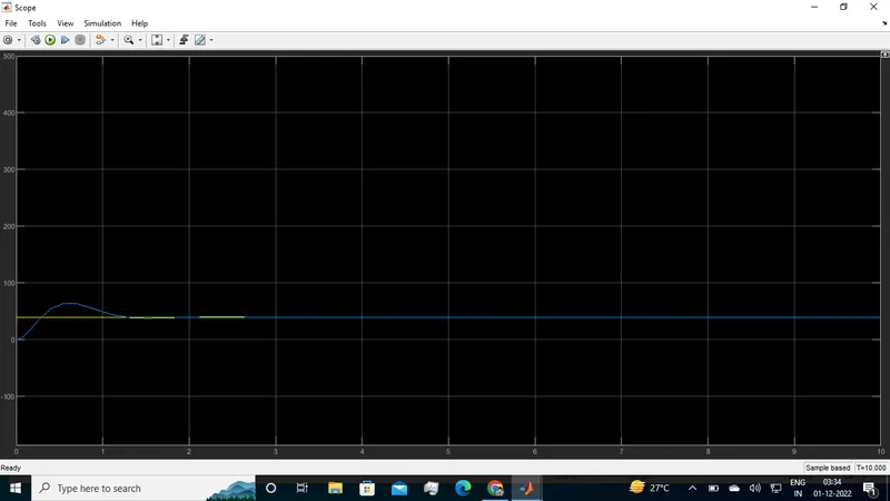
v) This total output value is given to the Input source signal to the Subsystem blosk we can obser this in (fig-3) above attached Simulink model.