Project-1: Powertrain for aircraft in runways
Solution:
1. Aircraft Gross Weight:
The aircraft gross weight (also known as the all-up weight and abbreviated AUW) is the total aircraft weight at any moment during the flight or ground operation.
An aircraft's gross weight will decrease during a flight due to fuel and oil consumption. An aircraft's gross weight may also vary during a flight due to payload dropping .
At the moment of releasing its brakes, the gross weight of an aircraft is equal to its takeoff weight. During flight, an aircraft's gross weight is referred to as the en-route weight or in-flight weight.
Weight of Various Types of Aircraft Weight :
1.Glider
Glider is a fixed wing plane that is supported in flight by the dynamic reaction of the air against its lifting surfaces, and whose free weight does not depend on an engine. Most gliders do not have an engine, although motor glider have small engines for extending their flight when necessary by sustaining the altitude (normally a sailplane is on a continuously descending slope) with some being powerful enough to take off self launch.
Weight of Glider planes : 110 kg - 200 kg
2.Powered Lift
A powered lift aircraft takes off vertically under engine power but uses a fixed wing for horizontal flight. These aircraft do not need a long runway to take off and land, like helicopters , but they have a speed and performance similar to standard fixed wing aircraft in combat or other situations.
Weight : 160 kgs
3.Fighter Aircraft
A fighter aircraft, often referred to simply as a fighter, is a military fixed wing aircraft designed primarily for air to air combat against other aircraft. The key performance features of a fighter include not only its firepower but also its high speed and manuverability relative to the target aircraft.
Weight : 13500 kgs
4.Transport Planes :
Military transport aircraft or military cargo aircraft are used to airlift troops, weapons and other military equipment to support military operations. Transport aircraft can be used for both strategic and tactical missions, and are often diverted to civil emergency relief missions.
Weight : 250,000 kgs
5.Aerobatic Planes
An aerobatic aircraft is an aerodyne (a heavier-than-air aircraft) used in aerobatics, both for flight exhibitions and aerobatic competitions
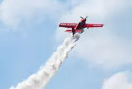
Weight : 771 kgs
2.Difference between ground speed and air speed:
| Ground Speed | Air speed |
| Ground speed is the airplane’s speed relative to the surface of the Earth | Airspeed is the speed relative to the air it is flying in. |
| Ground speed is what determines how fast an aircraft will get to its destination | Airspeed is what determines whether there is enough airflow around an aircraft to make it fly |
| Ground speed is simply the sum of airspeed and wind speed. | It is independent of ground speed. |
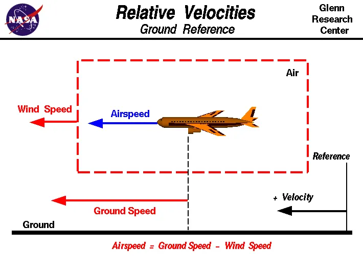
One of the most confusing concepts for young scientists is the relative velocity between objects. Aerodynamic forces are generated by an object moving through a fluid (liquid or gas). A fixed object in a static fluid does not generate aerodynamic forces. Hot air balloons "lift" because of buoyancy forces and some aircraft like the Harrier use thrust to "lift" the vehicle, but these are not examples of aerodynamic lift. To generate lift, an object must move through the air, or air must move past the object. Aerodynamic lift depends on the square of the velocity between the object and the air. Now things get confusing because not only can the object be moved through the air, but the air itself can move. To properly define the relative velocity, it is necessary to pick a fixed reference point and measure velocities relative to the fixed point. In this slide, the reference point is fixed to the ground, but it could just as easily be fixed to the aircraft itself. It is important to understand the relationships of wind speed to ground speed and airspeed.
Wind Speed
For a reference point picked on the ground, the air moves relative to the reference point at the wind speed. Notice that the wind speed is a vector quantity and has both a magnitude and a direction. The direction is important. A 20 mph wind from the west is different from a 20 mph wind from the east. The wind has components in all three primary directions (north-south, east-west, and up-down). In this figure, we are considering only velocities along the aircraft's flight path. A positive velocity is defined to be in the direction of the aircraft's motion. We are neglecting crosswinds, which occur perpendicular to the flight path but parallel to the ground, and updrafts and downdrafts, which occur perpendicular to the ground.
Ground Speed
For a reference point picked on the ground, the aircraft moves relative to the reference point at the ground speed. Ground speed is also a vector quantity so a comparison of the ground speed to the wind speed must be done according to rules for vector comparisons.
Airspeed
The important quantity in the generation of lift is the relative velocity between the object and the air, which is called the airspeed. Airspeed cannot be directly measured from a ground position but must be computed from the ground speed and the wind speed. Airspeed is the vector difference between ground speed and wind speed.
Airspeed = Ground Speed - Wind Speed
On a perfectly still day, the airspeed is equal to the ground speed. But if the wind is blowing in the same direction that the aircraft is moving, the airspeed will be less than the ground speed.
Examples
Suppose we had an airplane that could take off on a windless day at 100 mph (liftoff airspeed is 100 mph). We are at an airport with an east-west runway that is 1 mile long. The wind is blowing 20 mph towards the west and the airplane takes off going east. The wind is blowing towards the aircraft which we call a headwind. Since we have defined a positive velocity to be in the direction of the aircraft's motion, a headwind is a negative velocity. While the plane is sitting still on the runway, it has a ground speed of 0 and an airspeed of 20 mph:
Airspeed = Ground Speed (0) - Wind Speed (-20) = 20 mph
The airplane starts its take off roll and has a constant acceleration a. From Newton's second law of motion, the ground speed V at any time t is:
V = a * t
and the distance d down the runway at any time is:
d = 1/2 * a * t^2
For a fixed length runway, this specifies the time to be used in the velocity equation. Let's assume that at 5000 feet down the runway, the velocity is 80 mph. Then the airspeed is given by
Airspeed = Ground Speed (80) - Wind Speed (-20) = 100 mph
and the airplane begins to fly. Now another pilot, with exactly the same airplane decides to take off to the west. The wind is now in the same direction as the motion and this is called a tailwind. The sign on the wind speed is now positive, not negative as with the headwind. The acceleration along the ground is the same, so at 5000 feet down the runway, the ground speed is again 80 mph. The airspeed is then given by:
Airspeed = Ground Speed (80) - Wind Speed (20) = 60 mph
This airplane doesn't have enough airspeed to fly. It runs off the end of the runway.
Study 3: Why is it not recommended to use aircraft engine power to move it on the ground at Airport?
For movement on the ground the aircraft uses it own engine power, which is called taxing.
Although many aircrafts are capable of moving in backward using reverse thrust, as result the jet blast or prop wash might cause damage to the terminal building or equipment. Engine close to ground may also blow sand and debris forward and then suck them into the engine, causing damage to the engine.Therefore there are pushback trucks in the airport. A pushback truck lifts the front weel of the aircraft, their role in most airports is to move the aircraft awayfrom the parking spot on to the taxiways, which is called towing.
Unwanted consequences mainly arising from the unintended movement of the aircraft during engine running.
i) Effectively a loss of control can happen, especially during high power engine running. Damage can occur to the aircraft itself, other aircraft nearby or to airsidestructures.
ii) There is a risk of injury to ground support personnel who may be in relatively close proximity to the aircraft.
iii) It is easier for truck driver to see the surroundings better than the pilot sitting in the cockpit with limited window. The pushback driver knows the airport better than the pilot.
iv) It also saves fuel. virgin Atlantic hadproposed a new system in which pushback truck will move the aircraft all the way to runway to save fuel and reduce impact of environment.
v) The plane engines are very loud. When more than one plane will add up their sound, than it will not be pleasent for passangers and others near airport.
Study 4: How an aircraft is pushed to runway when its ready to take off?
Taxiing:
Taxiing (rarely spelled taxying) is the movement of an aircraft on the ground, under its own power, in contrast to towing or push-back where the aircraft is moved by a tug. The aircraft usually moves on wheels, but the term also includes aircraft with skis or floats (for water-based travel).
An airplane uses taxiways to taxi from one place on an airport to another; for example, when moving from a hangar to the runway. The term "taxiing" is not used for the accelerating run along a runway prior to takeoff, or the decelerating run immediately after landing, which is called the takeoff roll and landing rollout, respectively.
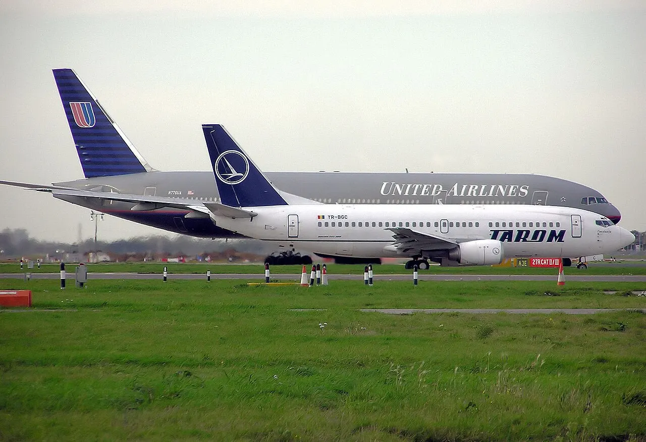
Towing:
Movement of large aircraft about the airport, flight line, and hangar is usually accomplished by towing with a tow tractor (sometimes called a “tug”). In the case of small aircraft, some moving is accomplished by hand pushing on the correct areas of the aircraft. Aircraft may also be taxied about the flight line but usually only by certain qualified personnel.
Towing aircraft can be a hazardous operation, causing damage to the aircraft and injury to personnel, if done recklessly or carelessly. This article outline the general procedure for towing aircraft. However, specific instructions for each model of aircraft are detailed in the manufacturer’s maintenance instructions and are to be followed in all instances.
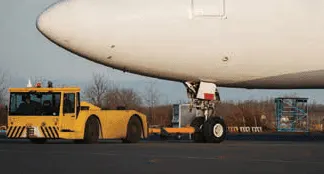
 |
| Figure 2. Example of a tow bar |
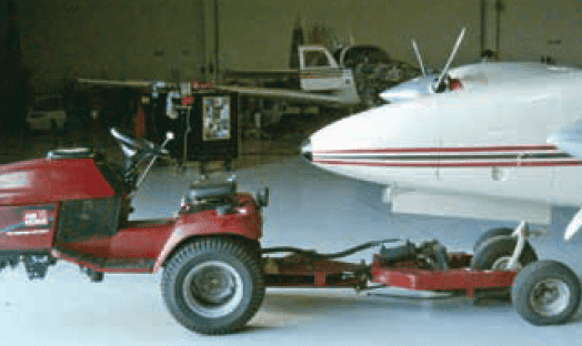 |
| Figure 3. Typical smaller aircraft tow tractor |
Takeoff:
Takeoff is the phase of flight in which an aerospace vehicle leaves the ground and becomes airborne.
For aircraft that take off horizontally, this usually involves starting with a transition from moving along the ground on a runway. For balloons, helicopters, and some specialized fixed-wing aircraft (VTOL aircraft such as the Harrier), no runway is needed. Takeoff is the opposite of landing.
Take off performance can be predicted using a simple measure of the acceleration of the aircraft along the runway based on force equilibrium.
The forces involved will be,
T – Thrust of propulsion system pushing aircraft along runway.
D – Aerodynamic Drag of vehicle resisting the aircraft motion.
F – Rolling resistance friction due to the contact of wheels or skids on the ground.
During take-off run the imbalance in these forces will produce an acceleration along the runway.
dVdt=T-D-Fm">dVdt=T−D−FmdVdt=T-D-Fm
where dV/dt is the acceleration along the runway and m is the mass of the vehicle.
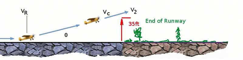
The procedure for take-off will be that the vehicle will accelerate until it reaches a safe initial flying speed. The pilot can then rotate the vehicle to an attitude to produce climb lift and it will ascend from the ground. The determination of this safe flying speed or rotation speed, VR, is a critical factor in determining take-off performance.
Take-off rules vary slightly depending on the aircraft category. Small commuter aircraft should be considered as meeting FAR 23 rules, transport category aircraft should comply with FAR 25 rules.
Small commuter aircraft :
For safety reasons VR is usually determined as being 1.1 × VSTALL or 1.05 × VMIN CONTROL
which ever is greater. Stall speed, VSTALL, is the lowest speed that the aircraft can be flown before the airflow starts to separate from wings as the angle of attack becomes too great. The wing is assumed in this case to be in take-off configuration or "clean".
It can be calculated based on knowledge of the aircraft take-off configuration and hence the maximum achievable lift coefficient CL(max). As shown in the previous section , to maintain level flight the lift produced must equal the weight, hence the stall speed can be calculated as,
Vstall=W12CL(max)ρS">Vstall=√W12CL(max)ρSVstall=W12CL(max)ρS
Minimum control speed, VMC is a more complex calculation and requires knowledge of the stall characteristics of the tailplane and elevator. For conventional aircraft there is only a small difference between VR calculations based on stall speed or minimum control speed.
As well as rotation speed there are other safety considerations as shown in the following Figure.
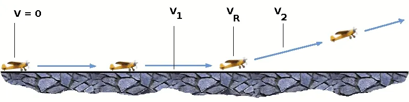
V1- Abort decision speed. Below this speed the take-off can be safely aborted. After this there will not be sufficient runway length to allow the aircraft to decelerate to a stop.
V2 – Safe climb speed. V2 must be no less than 1.2 * Vstall. Below this speed aircraft cannot attain sufficient climb rate.
Transport Aircraft :
VR must not be less than V1
VR must be greater than 1.05 * VMC
VR must be set so that aircraft achieves V2 before reaching a height of 35ft above the runway surface.
Aircraft must climb at a minimum gradient to avoid obstacles at the end of the runway. With engine failure on multi-engined aircraft, this speed should still be achievable.
Thrust:
The thrust of gas turbine or turbofan engines will be relatively constant during take-off. A good assumption is to use the manufacturer's values for maximum static thrust for take-off calculations.
T=Pshaft×ηV">T=Pshaft×ηVT=Pshaft×ηV
It is critical to correctly estimate the propeller efficiency for the particular aircraft velocity along the runway. At V=0 the efficiency is 0 so the above equation makes no sense. At V=VR the efficiency will be in the range 50% to 80% depending on the type of propeller system used and the thrust value at this point will be easy to obtain. In practice, the thrust obtained throughout the take-off roll is roughly constant so this end point value is a good approximation from V=0 to V=VR.
Drag:
The resistance to motion due to the air viscosity will give a drag of
D=12⋅Cd⋅ρ⋅A⋅V2">D=12⋅Cd⋅ρ⋅A⋅V2D=12⋅Cd⋅ρ⋅A⋅V2
where CD can be considered constant,
Although Drag Coefficient is constant, Drag will increase in proportion to the square of velocity.
Rolling Resistance:
The friction between aircraft and runway will be proportional to the normal force exerted by the aircraft on the runway.
F=μ(W-L)">F=μ(W−L)F=μ(W-L)
The normal force will be the difference between Weight of aircraft and Lift, the friction coefficient will be typically of a magnitude of 0.02 for a standard tarmac runway.
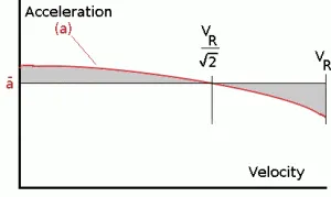
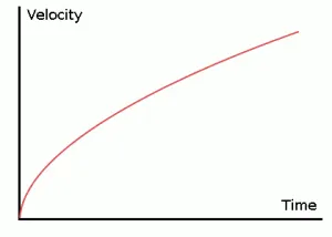
The rate of change of velocity can be predicted at any point on the take-off roll by substituting results for T, D and F into the initial equation for dV/dt. The subsequent velocity at any point can be found by integrating this resulting equation and the distance traveled found by then integrating the velocity.
Typically acceleration will be dominated by the drag component as thrust, weight and friction are relatively constant during this period. This leads to the result shown where acceleration is inversely proportional to velocity squared.
Due to the quadratic nature of acceleration change, an average value, (dVdt)avg=a">(dVdt)avg=a(dVdt)avg=a can be used for the take-off run. This average acceleration can be found at the point where,
V=VR2">V=VR√2V=VR2
This average acceleration can be used to simplify calculations and the take-off run can be calculated as an equivalent constant acceleration over the complete period of time (tR) taken to get from 0 to VR. For a constant acceleration take-off calculation.
VR=a.t">VR=a.tVR=a.t and distance travelled , s=12at2">s=12at2s=12at2
Rearranging leads to a relatively simple calculation to predict distance to rotation point.
s1=12VR2a">s1=12V2Ras1=12VR2a
From the rotation point, the end of the runway can be defined by the requirement to clear a 35ft obstacle at the end. During rotation it can be assumed that any residual excess thrust is absorbed in overcoming the lift induced drag as the aircraft begins to climb. Acceleration reduces and a constant flight speed during this climb phase can be assumed. The distance along the ground from rotation point to obstacle clearance point with thus be,
s2=35tanθ">s2=35tanθs2=35tanθ ft,
Take-off (Balanced) Field Length:
The required length of runway will be the sum of the distance required to get to rotation speed and the extra length required to clear a 50ft obstacle or the extra length required to allow for rapid braking if the pilot decides to abort take-off at the decision speed V1.
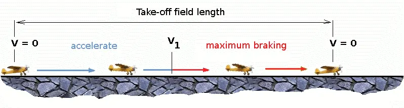
This length will typically be considerably longer than the distance required to achieve rotation (flying) speed. A rough approximation is that runway total length is around 2 x s1
Distance to V1 can be calculated in a manner similar to that shown for VR. The calculation of braking distance will require knowledge of the maximum braking friction coefficient that can be generated by the aircraft. This information should be available from manufacturer's data. Braking distance calculations should also be done without any assumption of reverse thrust from engines as during a take-off abort, engine power may not be available.
Landing:
The landing run can be calculated in a similar fashion to the take off distance. The aim is again to minimise the distance.
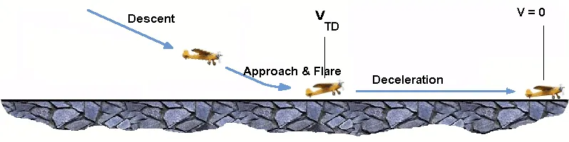
The touch down velocity should be approximately the stall speed of the aircraft in landing configuration. This will be achieved by a pitch manoeuvre during the flare portion of the approach which which increase drag an decelerate the aircraft to minimum flying speed.
The deceleration on the landing roll from VTD to V0 will be accomplished by braking and reverse thrust. This can be solved by the average acceleration approach that was used to estimate the take-off roll.
dVdt=-T-D-Fm">dVdt=−T−D−FmdVdt=-T-D-Fm
The negative acceleration or deceleration value will be based on friction coefficient for maximum braking and the value of reverse thrust (if available).
Braking force:
Stopping an aircraft landing at 180-200 mph requires a lot of braking force. To do this, the aircraft has brake unit on each of the wheels on the maingear assembly. On landing, pilots should use aerodynamic braking by applying extra back-pressure on the stick or yoke. Extreme caution should be used whenapplying brakes at any signicant speed, and only when the end of the runway is quickly approaching. Never step on the brakes to make a runway exit. Applyingthe brakes at too high a speed could burn the tires, wear out the brakes, or result in a ground loop or swerve.
Aircraft Disc Brake:
In the landing gear it is used to brake the wheels while touching the ground. These brakes are operated hydraulically. In most modernaircraft they are activated by the top section of the rudder pedals ("toe brakes"). In some older aircraft the bottom section is used instead ("heel brakes"). Leversare used in a few aircraft. Most aircraft are capable of differential braking.
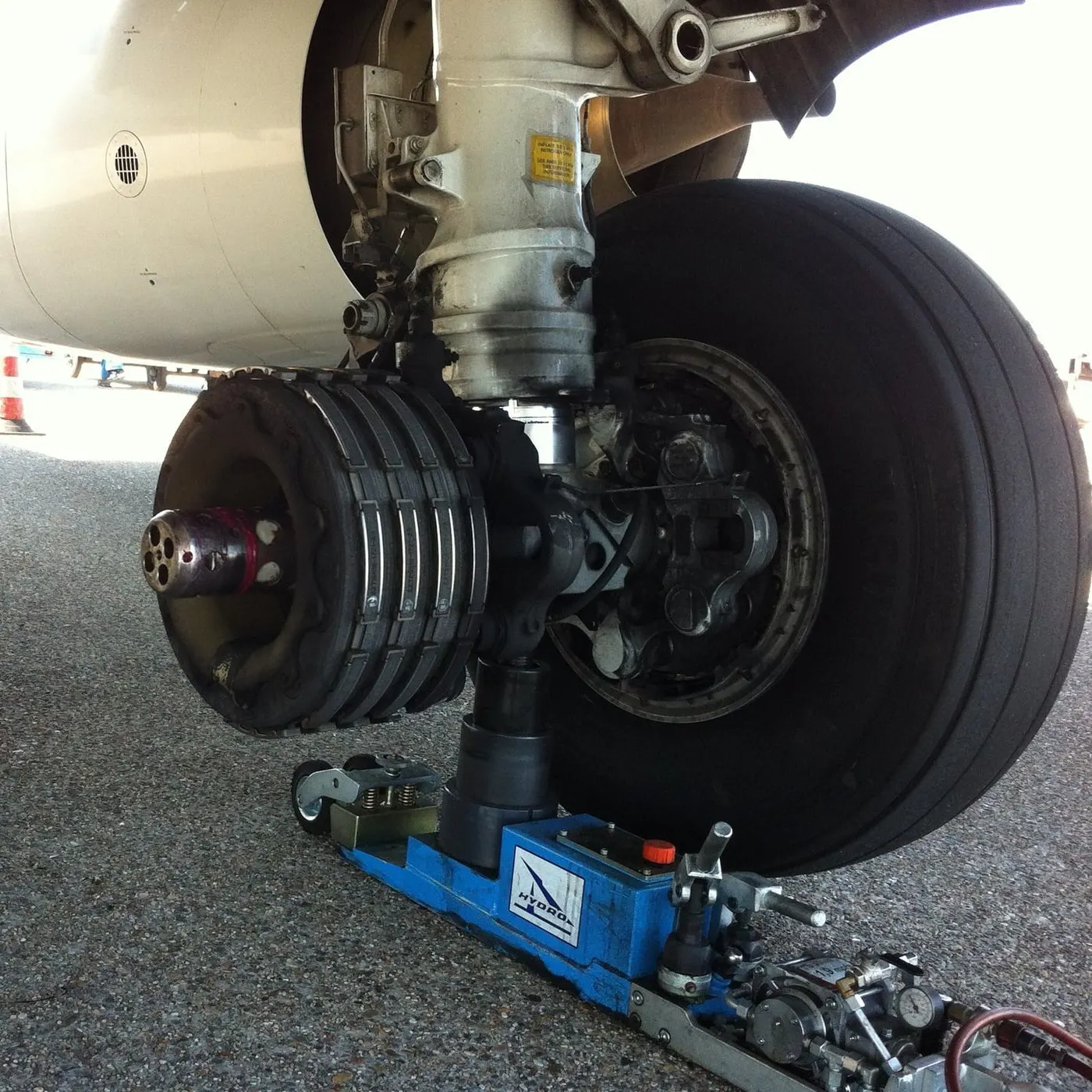
In addition to the brakes, there are two other systems which help slow the aircraft down on landing. The spoilers and the reverse thrust.
Spoilers
Have you noticed the large panels on the top of the wings raise up on touch down? These are the called the spoilers as they literally spoil the airflow over the wing. This dumps any remaining lift the wings are generating, allowing the wheels to take all the weight and achieve maximum efficiency from the brakes.
Reverse thrust
The final part of the braking process comes from reverse thrust. Just after we have touched down, we pull two levers on top of the thrust levers to engage the reverse thrust, a sort of “reverse gear” for jet engines.
There are two stages of reverse thrust — idle reverse and max reverse. Idle reverse is used on most landings and max reverse is used when the landing performance requires it, normally when the aircraft is landing at hot or high elevation airfields.
This forward directed airflow helps slow the aircraft down but is most efficient at high speeds. If using max reverse, we drop this down to idle reverse at 60 knots (70 mph) and then back to normal thrust as we vacate the runway at around 20 knots (25 mph).
Design and construction of the Aircraft tyre:
When it comes to safety, tyres are one of the most important components of aircraft. They help to absorb the shock of landing and provide cushioning. It also provides the necessary traction for braking and stopping of an aircraft.
An aircraft tyre is designed to withstand extremely heavy loads while landing, take off, taxing, and parking. The number of wheels required for aircraft increases with the weight of the aircraft, as the weight of the aeroplane needs to be distributed more evenly.
A Boeing 737NG & 737MAX uses 6 wheels, Boeing 787 uses 10 wheels, Boeing 777 uses 14 wheels and Airbus A380 uses 22 wheels. Aircraft tyres work under extreme conditions, carrying up to 340 tons and accelerating at over 250 km/hour at takeoff, in addition to enduring varied environmental stress when in flight and taxiing.
Carcass plies are used to form the tire. They are sometimes called casing plies. An aircraft tyre is constructed for the purpose it serves.
- They support the weight of an aircraft while it is on the ground.
- It also provides the necessary traction for braking and stopping of an aeroplane.
- Tyre also helps to absorb the shock of landing and provide cushioning the roughness of takeoff, roll-out, and taxi operations.
Unlike an automobile or truck tyre, it does not have to carry a load for a long period of continuous operation. However, an aircraft tyre absorbs the high impact loads of landing, and also it’s operating at high speeds for a short time when required.
Retreading – Retreading is methods of restoring a worn tyre by renewing the tread area or by renewing the tread area plus one or both sidewalls. Repairs are included in the tyre retreading process.
Load Rating – Load rating is the maximum permissible load at a specified inflation pressure.
Ply Rating – Ply Rating is used to identify the maximum recommended load rating and inflation pressure for a specified tyre. It is an index of tyre strength.
Speed Rating – The speed rating is the maximum takeoff speed to which the tyre has been tested.
Skid Depth – Skid depth is the distance between the tread surface and the deepest groove as measured in the mould.
Aircraft tyres must have an approved speed and load rating and have sufficient clearance when retracted through landing gear to allow for tyre growth. Tyre growth is the increase in the size of the tyre due to centrifugal forces at high speed.
Aircraft tires may be Tube-type or Tubeless
Tubeless tyres are more advantageous over tube-type. There is no longer the use of tube-type tyre in recent aviation. Nowadays all airliners are using tubeless tyres. Tubeless that are meant to be used without a tube has the word TUBELESS on the sidewall of the tyre.
Aircraft tyres may be Radial or Bias
Almost all airliners are using Radial tyre. Bias is an older design, and it’s mainly used for road vehicles. Radial tyres have the word RADIAL on the sidewall. Radial tires are more expensive than bias-ply tyres. Radial tires are in demand because of their lower life cycle cost and long term value.
Chines are also called deflectors. Chine tyre used on the nose wheel of aircraft, specially fuselage-mounted jet engines. It diverts runway water away from the engine inlets.
Chines are circumferential protrusions that are moulded into the sidewall of nose tyres that deflect water sideways to help reduce excess water ingestion into the engines. Tyres may have chines on one or both sides, depending on the number of nose tyres on the aircraft.
Aircraft tires generally operate at high pressures, up to 200 psi (14 bar; 1,400 kPa) for airliners, and even higher for business jets. The main landing gear on the Concorde was typically inflated to 232 psi (16.0 bar), whilst its tail bumper gear tires were as high as 294 psi (20.3 bar).
6. A. calculating the force and power required to push / pull an aircraft by a towing vehicle:
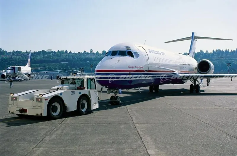
The forces required to push/ pull an aircraft by a towing are rolling resistance force and areodynamic drag force. 1) Rolling resistance force:- As we have discussed in part-A 5c. It is the force resisting the motion when a body (such as a ball, tire, or wheel) rolls on a surface. Its governing equation is given as
F = CN
F=C*m*g
where,
Crr= Rolling resistance coefficient m=Mass of the body g= acceleration due to gravity
2)Aerodynamic Drag Force:
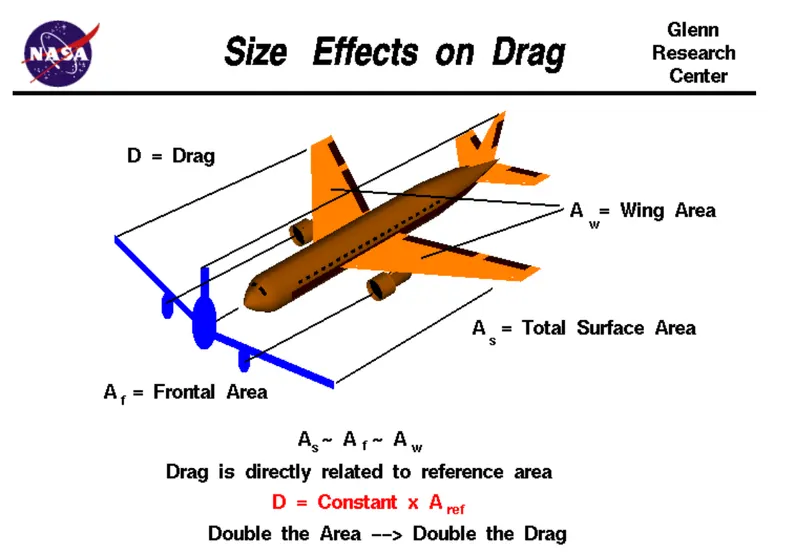
It is the force opposing the motion of the body. The drag coefficient is a common measure in automotive design as it pertains to aerodynamics, Drag is a force that acts parallel to and in the same direction as the airflow. The drag coefficient of an automobile measures the way the automobile passes through the surrounding air. When automobile companies design a new vehicle, they take into consideration the automobile drag coefficient in addition to the other performance characteristics. Aerodynamic drag increases with the square of speed; therefore, it becomes critically important at higher speeds. Reducing the drag coefficient in an automobile improves the performance of the vehicle as it pertains to speed and fuel efficiency. The governing equation of these force is given as following:
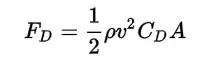
where.
F{D} = dra force
rho = r density of the air
น = flow velocity relative to the object
C{D} = drag coefficient
A = reference area
Calculation:
let us assume that,
Mass of Towing Vehicle= 40,000kg
Mass of aircraft = 155,000kg
Total mass (m)= 40,000+155,000 =195,000kg
Frontal Area of the aircraft (A) =18 m²
Speed of the vehicle (2)=25Kmph
converting it into m/sec
u=25*(1000/3600)=6.9445m/sec
Drag coefficient (Cd) =0.75
Air density (P)=1.225Kg/m³
Calculating Rolling resistance Force (Frr) =Crr*m*g
=0.01*195.000*9.8
= 19.11ON
Calculating Aerodynamic Drag Force (Fd)=0.5*p Cd*A* v^2
=0.5 *1.225 *18* 0.75* (6.9445)2
=398.769N
Therefore the total Force required to push/pull the aircrcraft by the towing vehicle (F) Frr+Fd
=19,110+398.769
=19,508.769 N
Calculating the power (p) =Force*Velocity
= 19508.769* 6.9445
=135.478kW
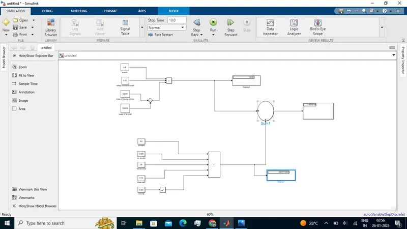
Explaination:
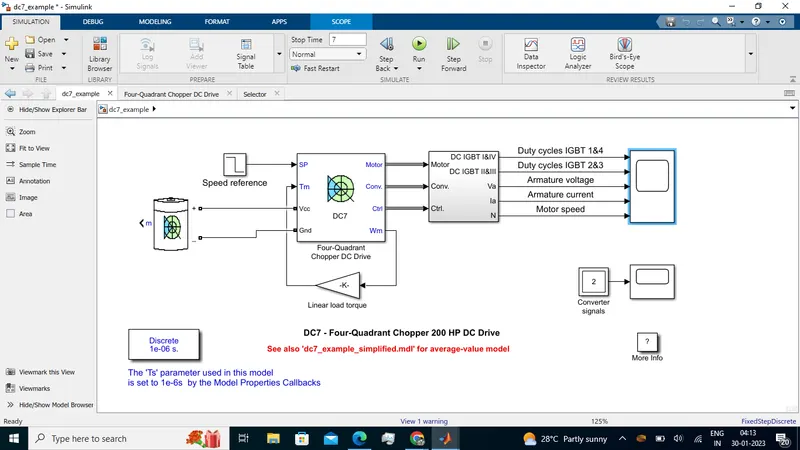
In order to understand the above simulink model we do reverse engineering
• For calculating power we have to multiply both total force(F) and velocity in m/sec for this we have used 'product' block (P-FV).
• For calculating the Total Force(F) we have added both Frr & Fd by using 'Surn' block as shown in the above figure
• To find the value of rolling resistance (Frr) we used product to multiply the values Crr., Total mass(m) & gravity (g) which are to be entered in the 'Constant block.
. Similarly for calculating Drag force(Fd) we have to multiply the velocity in m/sec.Drag coefficient, Frontal area of aircraft(A) and a constant value 0.5 which are to be entered in constant block.
• In order to convert velocity in Kmph to m/sec we have multiplied it with 5/18.
7) A. Designing an electric powertrain with type of motor, it's power rating, and energy requirement to fulfill aircraft towing application in Simulink. Estimate the duty cycle range to control the aircraft speed from zero to highest. Make all required assumptions. Prepare a table of assumed parameters. Draw a block diagram of powertrain.
Block Diagram of Powertrain:
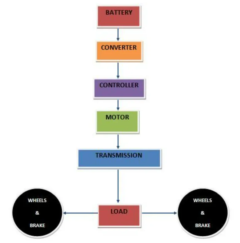
Based on the calculations done in 6A.
Force required to push/pull the aircraft =19.508 KN
Power required =135.478 kw
Let us assume,
The Radius of the Tyre for the Tug - 25inches =0.635m
Gear ratio=8
Transmission Effeciency (nt) =87%
Motor Efficiency (nm)=95%
then,
Torque required for the wheels (Tw)=Total Force *Radius in meters
=19.508 *0.635
=12.387KNm
Motor Torque-Wheel torque/(Gear ratio'nt)
=12.387/(8 0.87)
=1.778KNm
For nm =95%. The required motor Torque (Tm)= 1.778/0.95 =1.871 kNm
Similarly. The total power required by the motor considering all the efficiencies (Pt) = 135.478/(0.87*0.95)=163.917Kw
Let us assume the towing operation was done for a 15 minutes (0.25Hrs) duration.
Then, Total Energy consumed = 163.917* 0.25=40.98 KWh
If we consider the battery capacity=220 kw is used by the towing vehicle then. The duty cycle range to control the speed from O to max speed (3m/s) is given as
Duty Cycle (d)= (Required Power)/ (Rated power)= 163.917/220 =0.75
Therefore the controller will be able to provide a duty cycle ranging from 0 to 75% in order to control the towing speed.
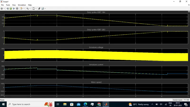
Simulink Diagram of powertrain: