Week-7 Challenge: DC Motor Control
The Bipolar Junction Transistor (BJT) when used for power switching applications, operates as an IGBT. When it is conducting (BJT operating in the saturated region), a forward voltage Vf is developed between collector and emitter (in the range of 1 V). Therefore, the IGBT block can be used to model the BJT device.
The IGBT block does not simulate the gate current controlling the BJT or IGBT. The switch is controlled by a Simulink signal . The DC motor uses the preset model (5 HP 24V 1750 rpm). It simulates a fan type load (where Load torque is proportional to square of speed). The armature mean voltage can be varied from 0 to 240 V when the duty cycle (specified in the Pulse Generator block) is varied from 0 to 100%.
The H-bridge consists of four BJT/Diode pairs (BJT simulated by IGBT models). Two transistors are switched simultaneously: Q1 and Q4 or Q2 and Q3. When Q1 and Q4 are fired, a positive voltage is applied to the motor and diodes D2-D3 operate as free-wheeling diodes when Q1 and Q4 are switched off. When Q2 and Q3 are fired, a negative voltage is applied to the motor and diodes D1-D4 operate as free-wheeling diodes when Q2 and Q3 are switched off.
An H-bridge is built of four switches that control the flow of current to a load. In the image above, the load is the M connecting the two sets of switches. Using one current source, you can drive current in two directions by closing two switches.
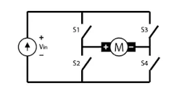
H-bridge drivers are a long established means for enabling bidirectional motor driving. By using one, rotation of the motor can be driven, and the polarity of the supply to the motor can be swapped in order to change the direction of rotation. It can also take care of braking, when this is required.
o control the speed of the motor you apply a Pulse Width Modulation (PWM) signal to the Enable line. The shorter the pulse width, the slower the motor will spin
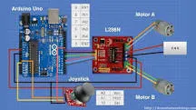
Connect your battery snap to one corner of the power bus. The convention is to connect the positive voltage to the upper row and the negative to the bottom row to denote the HIGH and LOW signals respectively. We then connect the top and bottom sets of power buses
Unfortunately, when using an H-bridge circuit, a single flyback diode will not suffice. Since there are multiple current pathways, there must be four diodes to provide a path for the induced voltage
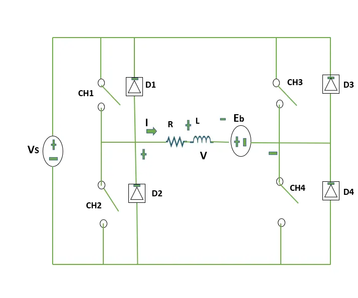
2. Four-Quadrant Chopper can operates in all four modes (Forward Motoring,Forward Braking, Reverse Motoring and Reverse Braking), but H-bridge can operate only in two modes (Forward and Reverse). 2. In Four-Quadrant Chopper Regenerative Braking is possible, but H-bridge Regenerative Braking is not possible.
QUADRANT-I
- When a motor draws power from supply, the voltage and current are in the same direction.
- Now the motor is said to be in motoring operation, its operation corresponds to first quadrant.
- In the first quadrant power developed is positive and the machine is working as a motor supplying mechanical energy. The I (first) quadrant operation is called Forward Motoring.
QUADRANT-II
- If there is a possibility of reversing the current direction keeping the voltage polarity same, the motor is said to be operating in second quadrant.
- This happens when regenerative braking is applied on the motor.
- During regeneration operation, reverse power flow will happen. ie, power will fed back to the supply system.
- Second quadrant operation is known as Braking. In this quadrant the direction of rotation is positive, and the torque is negative, and thus, the machine operates as a generator developing a negative torque, which opposes the motion.The kinetic energy of the rotating parts is available as electrical energy which may be supplied back to the mains. In dynamic braking dissipated the energy is dissipated in the resistance.
QUADRANT-III
- If the voltage polarity and load current are reversed simultaneously, the motor’s operation will be in the opposite direction ( but the power is consumed by the load).
- This operation is corresponds to the third quadrant and even now it is said to be in motoring operation (in reverse direction).
- The third quadrant operation is known as the reverse motoring. The motor works, in the reverse direction. Both the speed and the torque have negative values while the power is positive.
QUADRANT-IV
- If the voltage polarity is reversed maintaining the current direction from source to load, the power reversed and the operation corresponding to the fourth quadrant.
- Now the motor is said to be in reverse regeneration operation (ie, regeneration in reverse direction).
- In the fourth quadrant, the torque is positive, and the speed is negative. This quadrant corresponds to braking in the reverse regenerative braking mode.
FOUR QUADRANT CHOPPER CIRCUIT DIAGRAM:
2 ANSWER
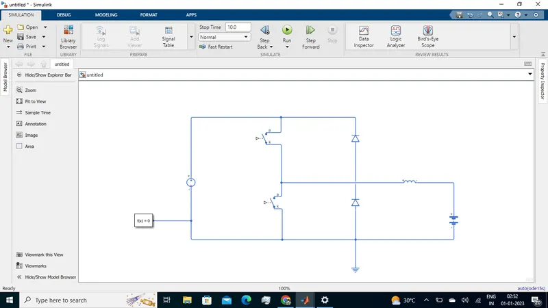
A chopper is a device that converts fixed DC input to a variable DC output voltage directly. Essentially, a chopper is an electronic switch that is used to interrupt one signal under the control of another.
he two-quadrant chopper operates in the first and second quadrants, allowing positive and negative output current.
The Two-Quadrant Chopper DC Drive (DC6) block represents a two-quadrant, DC-supplied, chopper (or DC-DC PWM converter) drive for DC motors. This drive features closed-loop speed control with two-quadrant operation. The speed control loop outputs the reference armature current of the machine.
QUADRANT-I
- When a motor draws power from supply, the voltage and current are in the same direction.
- Now the motor is said to be in motoring operation, its operation corresponds to first quadrant.
- In the first quadrant power developed is positive and the machine is working as a motor supplying mechanical energy. The I (first) quadrant operation is called Forward Motoring.
QUADRANT-II
- If there is a possibility of reversing the current direction keeping the voltage polarity same, the motor is said to be operating in second quadrant.
- This happens when regenerative braking is applied on the motor.
- During regeneration operation, reverse power flow will happen. ie, power will fed back to the supply system.
- Second quadrant operation is known as Braking. In this quadrant the direction of rotation is positive, and the torque is negative, and thus, the machine operates as a generator developing a negative torque, which opposes the motion.The kinetic energy of the rotating parts is available as electrical energy which may be supplied back to the mains. In dynamic braking dissipated the energy is dissipated in the resistance.
3 ANSWER
Construction of Brushless DC motor
In this motor, the permanent magnets attach to the rotor. The current-carrying conductors or armature winding are located on the stator. They use electrical commutation to convert electrical energy into mechanical energy.
The main design difference between a brushed and brushless motors is the replacement of mechanical commutator with an electric switch circuit. A BLDC Motor is a type of synchronous motor in the sense that the magnetic field generated by the stator and the rotor revolve at the same frequency.
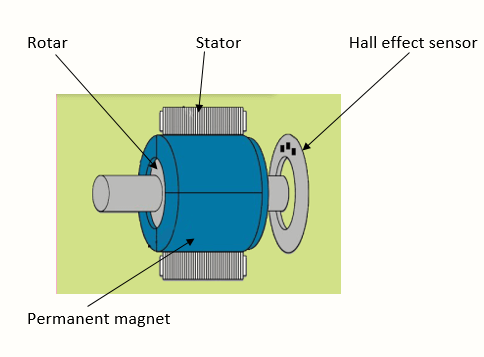
Brushless motor does not have any current carrying commutators. The field inside a brushless motor is switched through an amplifier which is triggered by the commutating device like an optical encoder.
The layout of a DC brushless motor can vary depending on whether it is in “Out runner” style or “Inrunner” style.
-
Outrunner – The field magnet is a drum rotor which rotates around the stator. This style is preferred for applications that require high torque and where high rpm isn’t a requirement.
-
In runner – The stator is a fixed drum in which the field magnet rotates. This motor is known for producing less torque than the out runner style, but is capable of spinning at very high rpm.
Working Principle of Brushless DC motor
BLDC motor works on the principle similar to that of a BRUSHED DC MOTOR The Lorentz force law which states that whenever a current carrying conductor placed in a magnetic field it experiences a force. As a consequence of reaction force, the magnet will experience an equal and opposite force. In the BLDC motor, the current carrying conductor is stationary and the permanent magnet is moving.
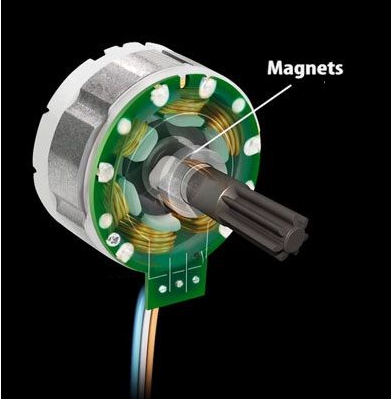
When the stator coils get a supply from source, it becomes electromagnet and starts producing the uniform field in the air gap. Though the source of supply is DC, switching makes to generate an AC voltage waveform with trapezoidal shape. Due to the force of interaction between electromagnet stator and permanent magnet rotor, the rotor continues to rotate.
With the switching of windings as High and Low signals, corresponding winding energized as North and South poles. The permanent magnet rotor with North and South poles align with stator poles which causes the motor to rotate.
Advantages of Brushless DC motor
- Less overall maintenance due to absence of brushes
- Reduced size with far superior thermal characteristics
- Higher speed range and lower electric noise generation.
- It has no mechanical commutator and associated problems
- High efficiency and high output power to size ratio due to the use of permanent magnet rotor
- High speed of operation even in loaded and unloaded conditions due to the absence of brushes that limits the speed
- Smaller motor geometry and lighter in weight than both brushed type DC and induction AC motors.
- Long life as no inspection and maintenance is required for commutator system
- Higher dynamic response due to low inertia and carrying windings in the stator
- Less electromagnetic interference
- Low noise due to absence of brushes
Limitations of Brushless DC motor
- These motors are costly
- Electronic controller required control this motor is expensive
- Requires complex drive circuitry
- Need of additional sensors
Applications of Brushless DC motor
Brushless DC motors (BLDC) use for a wide variety of application requirements such as varying loads, constant loads and positioning applications in the fields of industrial control, automotive, aviation, automation systems, health care equipments etc.
- Computer hard drives and DVD/CD players
- Electric vehicles, hybrid vehicles, and electric bicycles
- Industrial robots, CNC machine tools, and simple belt driven systems
- Washing machines, compressors and dryers
- Fans, pumps and blowers.
Hope this article helps you to understand about the brushless dc motor working principle and applications. We athope that you found it interesting and that you will come back for more of our educational blogs.