Project - Speed Control of a Direct Current (DC) motor
%dc motor parameters
J=0.02; %moment of inertia of rotor
B=0.05; %motor viscous friction
Km=0.1; %back emf
Kt=0.1;%motor torque constant
Ra=2;%resistance of armature
La=0.5; %inductance of armature
%the motor equations
theta_dot_dot= kt*i-B*theta_dot/J;
i_dot=V-Km*theta_dot-Ra*i/La;
%these two equations govern modeling of DC motor
%the reference speed in rpm
S_ref=1500;
%PID parametes after tuning
Kp=1.388
ki=3.173
kd=0.059
% step 1: the ref speed is compared with measured speed
%step 2: the error (ref speed-measured speed) is given to the input of PID controller
%step3: the output of PID controller is given as voltage input to DC motor and output is given as theta_dot
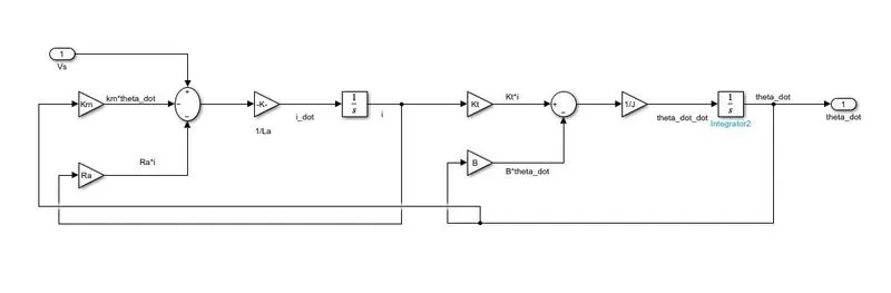
the above figure shows dc motor subsystem
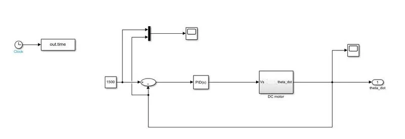
the above figure shows the system model
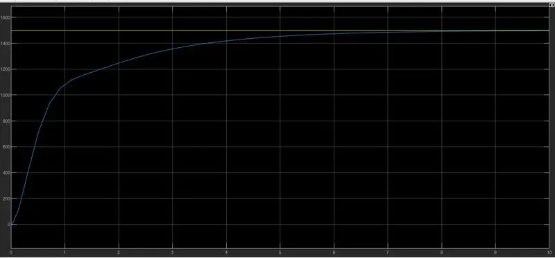
the above picture is outut before tuning of pid controller
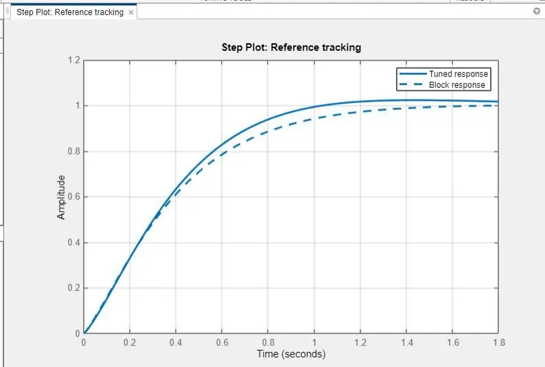
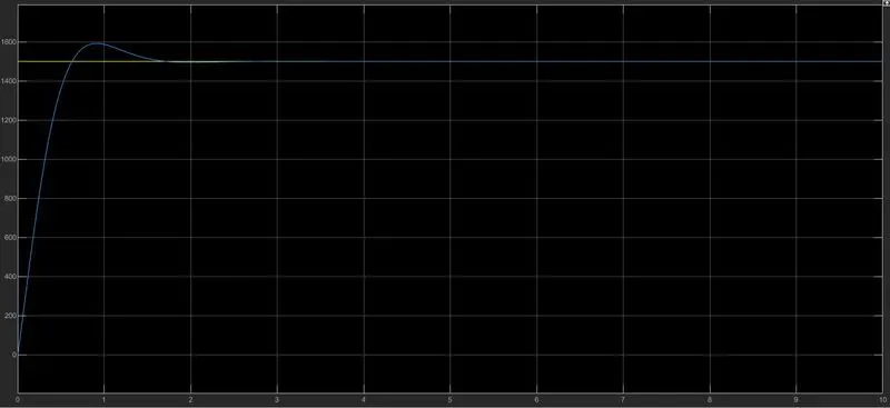
after tuning of PID the grapha and time domain parameters are shown
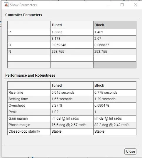
from above block we can clearly see the peak overshoot is <5% and settling time <2sec as per design specifications asked in the question