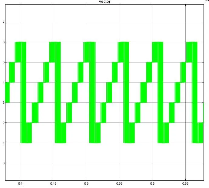
Project 2 - Modeling of 3 phase Induction Motor Drive
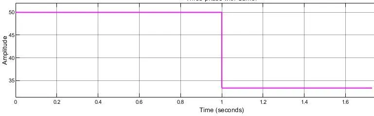
This is the most popular method for controlling the speed of an induction motor. if the supply frequency is reduced while maintaining the rated supply voltage, the air gap flux will tend to saturate. This will cause excessive stator current and distortion of the stator flux wave. Therefore, the stator voltage should also be reduced in proportion to the frequency to keep the air gap flux constant. The magnitude of the stator flux is proportional to the ratio of the stator voltage and frequency. Thus, if the ratio of voltage to frequency is kept constant, the flux remains constant. Also, by keeping U/F constant, the torque developed remains approximately constant. This method provides higher operational efficiency. Therefore, most AC drives use the constant U/F method (or the variable voltage, variable frequency method) for speed control. Along with a wide range of speed control, this method also offers a "soft start" option.
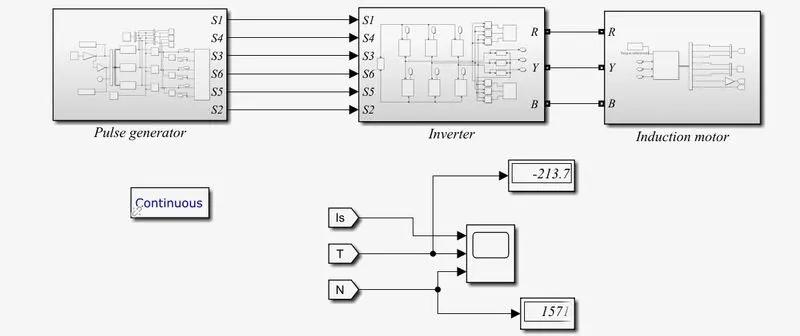
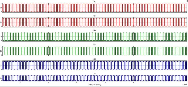
Pulse generator:
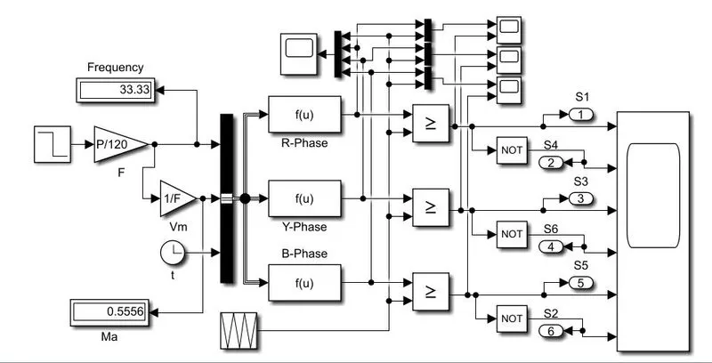
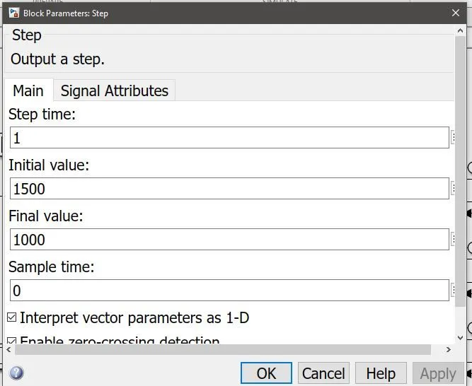
gate pulses :
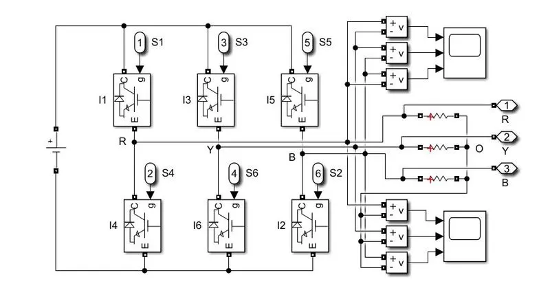
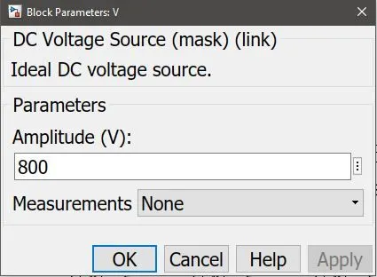
Inverter:
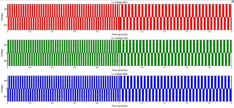
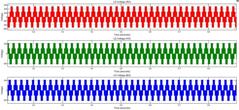
AC voltage generated:
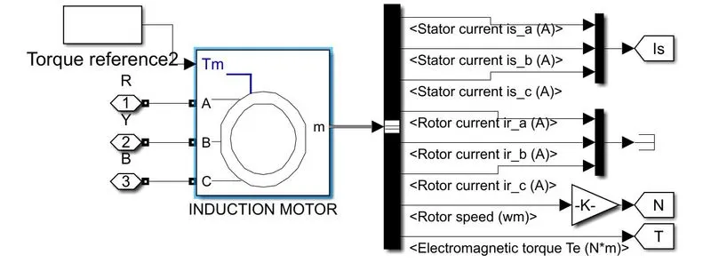
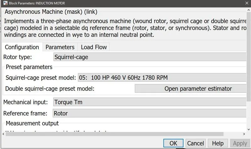
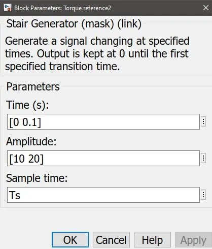
Induction machine:
OUtputs:
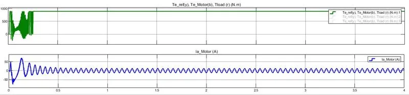
stator current:


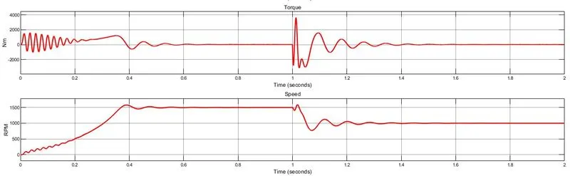
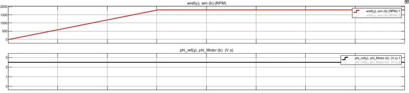
TORQUE AND SPEED:
frequency:
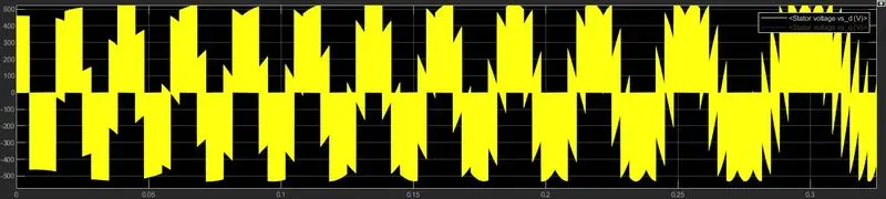
Vstator_daxis
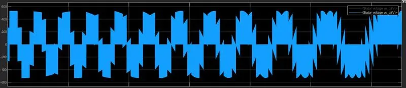
Vstator_qaxis:
2.
3.
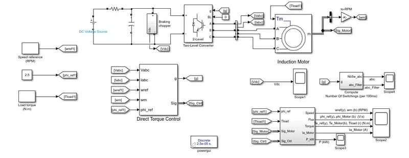
Direct torque control (DTC) is one of the methods used in variable frequency drives to control the torque (and thus the speed) of three-phase AC electric motors. This involves calculating an estimate of the motor's magnetic flux and torque based on the measured motor voltage and current.Direct Torque Control (DTC) is an optimized AC drive control principle where the inverter switching directly controls the motor variables: flux and torque.The measured input values for DTC control are motor current and voltage. The voltage is defined from the DC bus voltage and the inverter switch positions.The voltage and current signals are inputs to an accurate motor model that produces an accurate true value of stator flux and torque every 25 microseconds.
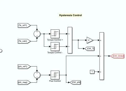
Two-level motor torque and flux comparators compare actual values with reference values created by torque and flux reference controllers.
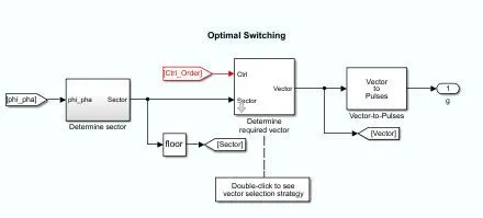
The outputs from these two-level controllers are updated every 25 microseconds to indicate whether torque or flux needs to be changed.Depending on the outputs from the two-level controllers, the switching logic directly determines the optimal positions of the inverter switches. That's why everyone
the voltage pulse is determined separately at the "atomic level". The inverter switch positions again determine the motor voltage and current, which in turn affect
torque and motor flux and the control loop is closed.
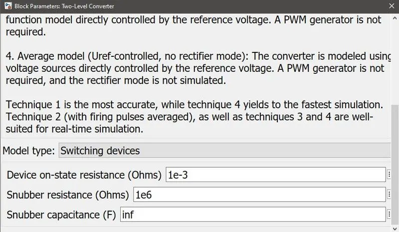
Braking chopper:
flux and torque calculation:
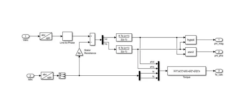
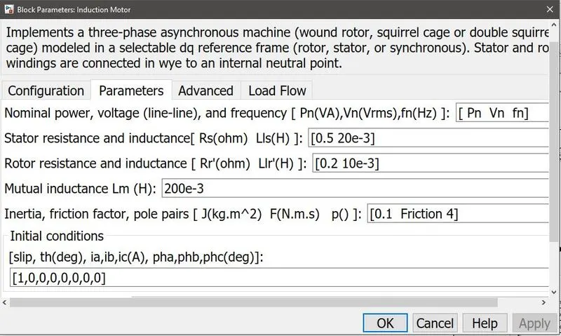
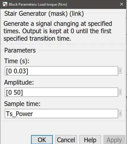
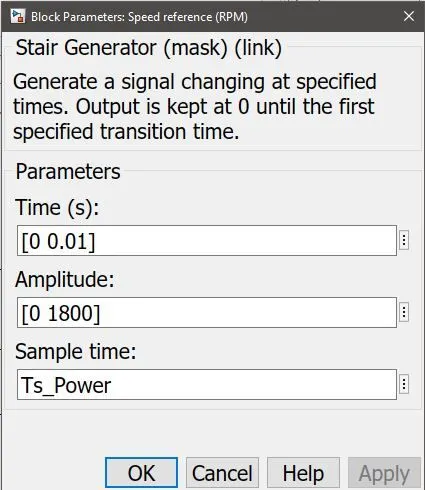
output:
ABC filter:
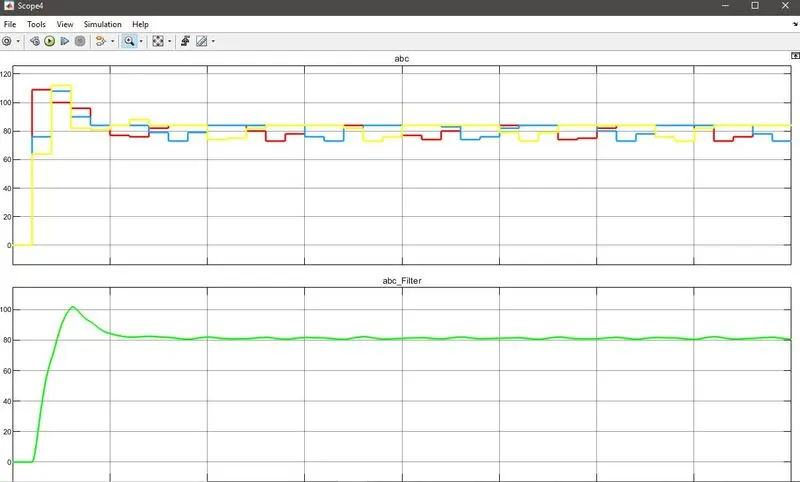
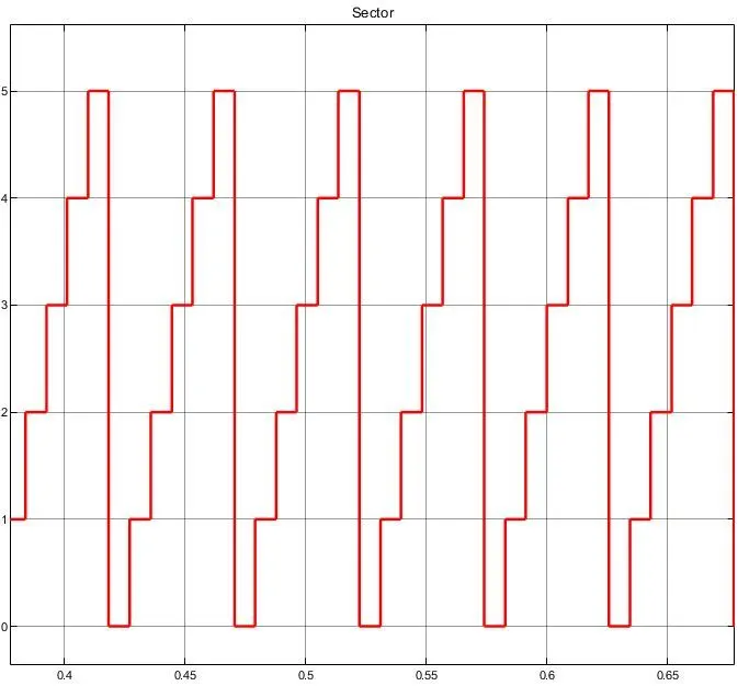
Sector:
Vectors: