Project 1
1. Buck converter CCM mode:
Input voltage- 40-50V;
output voltage-30V, Power=500W;
Fs=100khz;
D=vout/vin=30/50=0.6;
Il=Iout=500/30=16.66A;
Rload=Vout/Iout=30/16.66=1.8ohm;
let us take ripple current <40%,
L=Vout(1-D)/Fs*del(Il)=30*(1-0.6)/100k*(0.4*16.66)=0.18uH;
Assume voltage ripple = 5%
C=0.55mF;
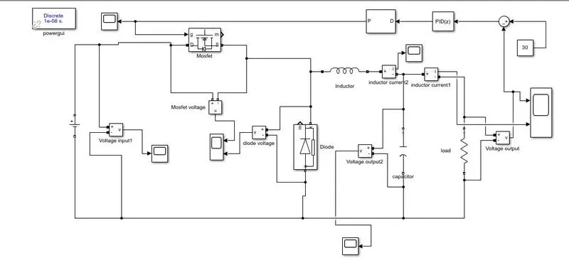
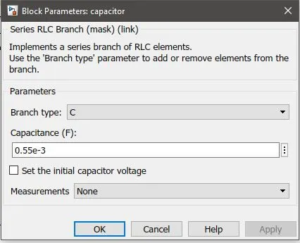
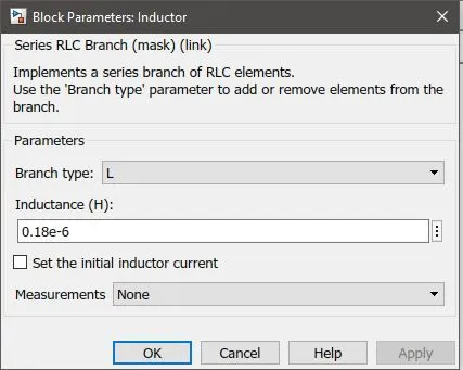
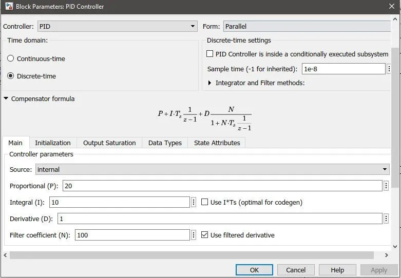
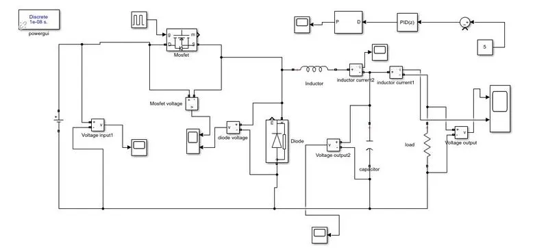
Case 1: This PID controller has been designed for output voltage 30V and vout is being compared with 30. we will change the load resistance and check wether 30V is coming or not.
R=1.8ohm
output graphs:
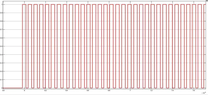
PWM:output of pwm generator and gate pulse that goes into mosfet.
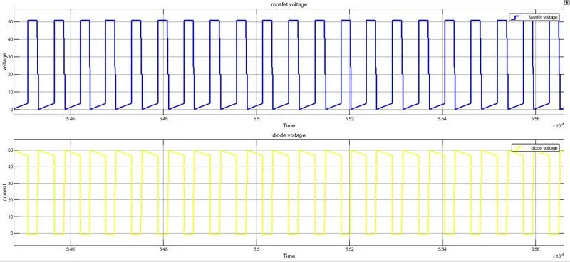
Mosfet and diode voltages output:
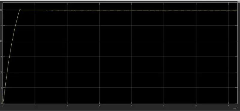
Capacitance voltage:
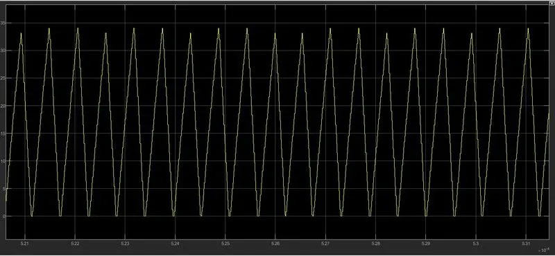
Inductor current:
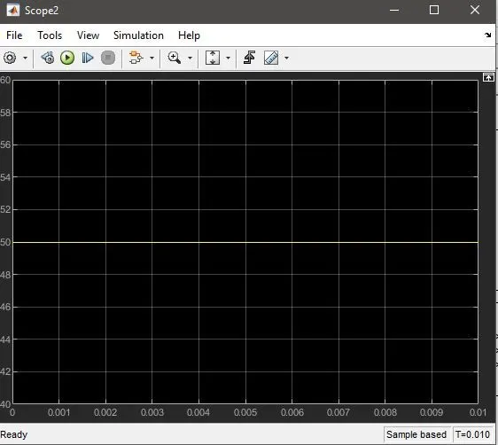
Input Voltage :
Output voltage and current:
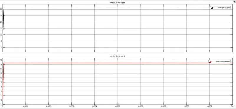
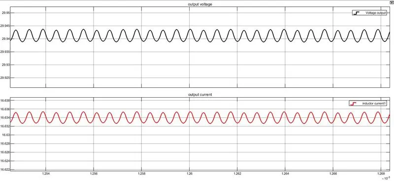 The above graph shows the output voltage=30V and output current=16.66A.
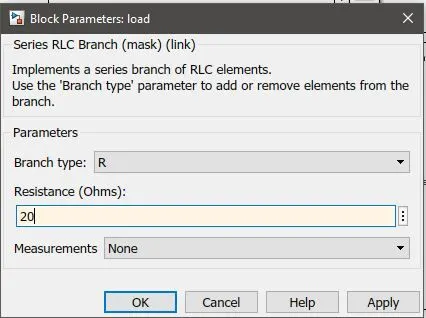
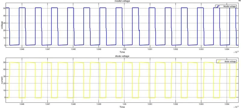
case 2: R=20ohm;
mosfet and diode voltages:
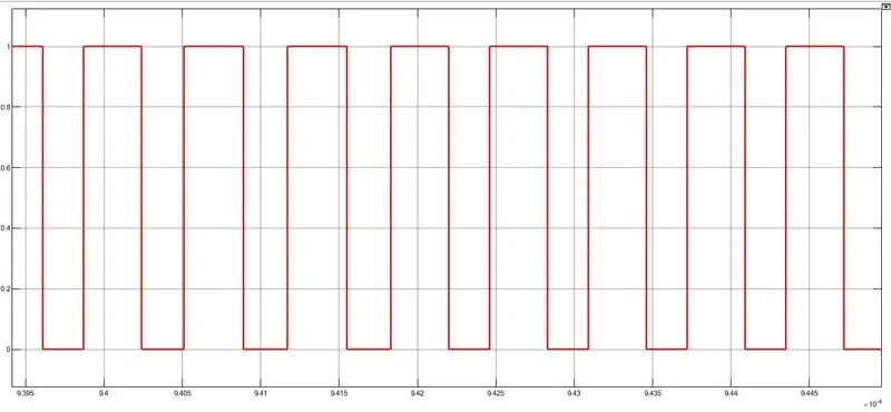
Gate pulse of MOSFET:
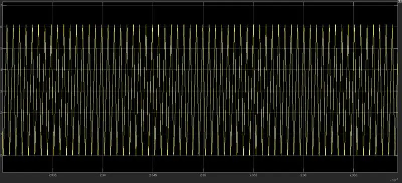
Inductor current:
Voltage and current Output graphs:
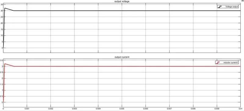
we can see output voltage of 30V has been achieved with output current reduced to 3A.
2. BUCK CONVERTER DISCONTINUOS MODE:
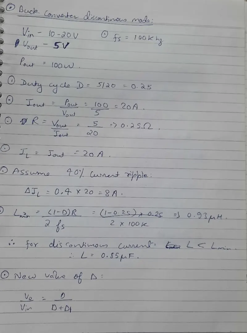
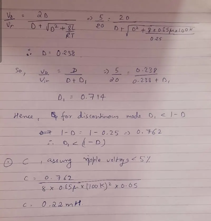
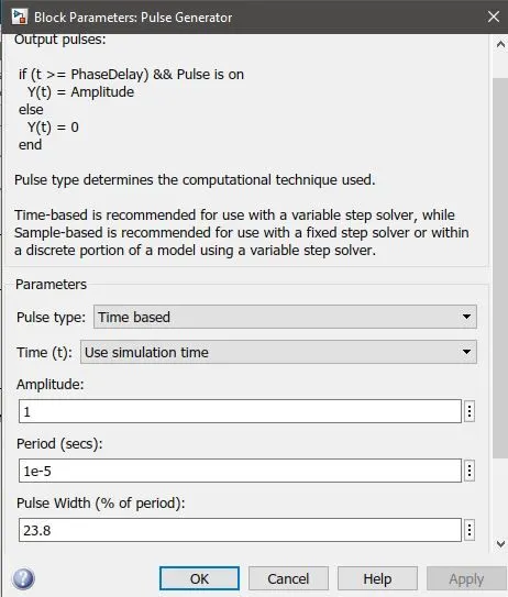
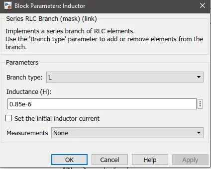
Case1: When we do not connect PID controller and only pulse generator is given with 23.8% width.
outputs:
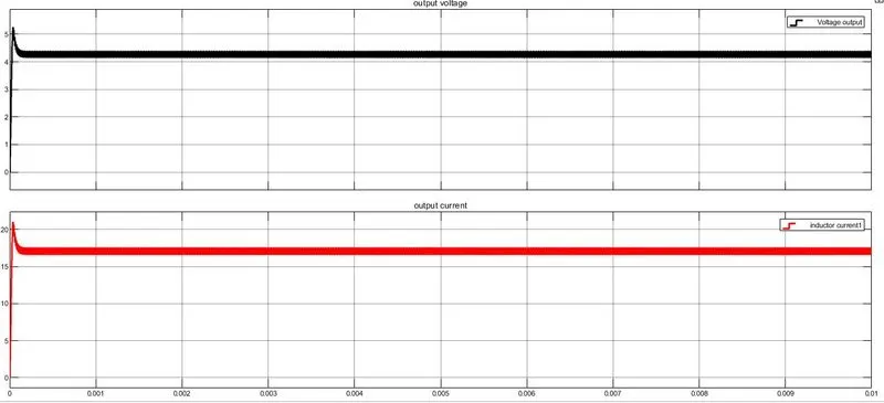
we can see that output voltage has clearly failed to reach 5V that was the desired voltage.
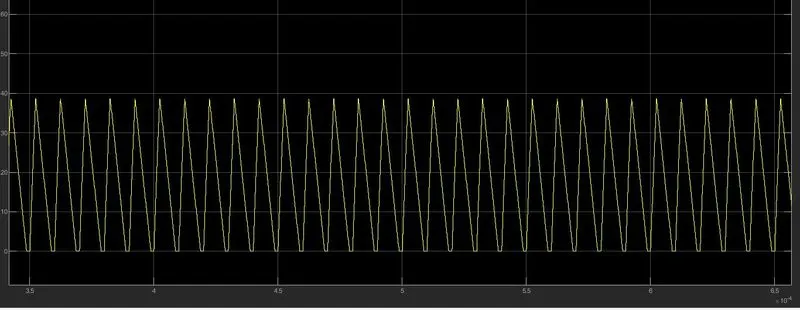
Inductor current is discontinuous in nature, as it is becoming zero.
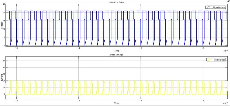
The above graphs are mosfet and diode voltages.
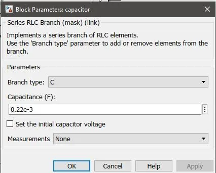
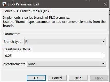
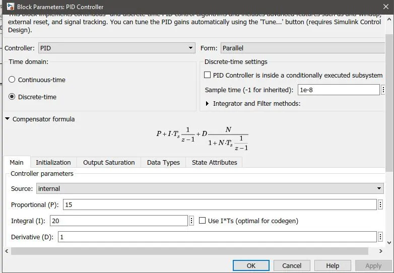
case 2: PID controller design with R=0.25 ohm.
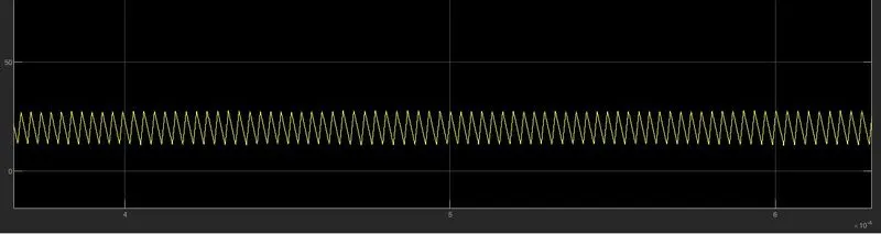
Inductor current: We can see see inductor current is not zero.
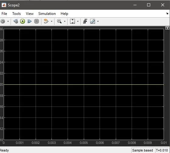
Resistance:
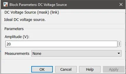
Vin:
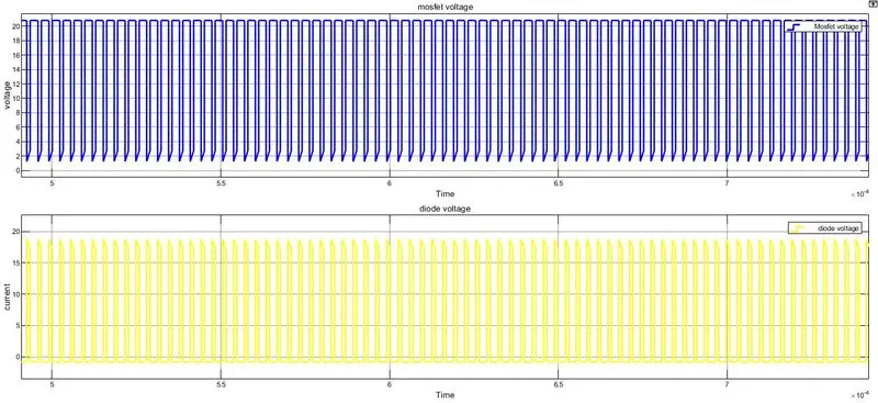
Diode and mosfet voltages:
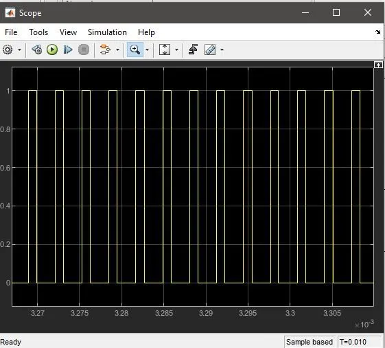
Gate pulse :
voltage and current output:
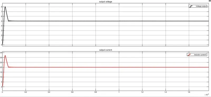
we can see the voltage has reached its desired value of 5V with 20A current.
case 3: load resistance changed from 0.25 to 5v.
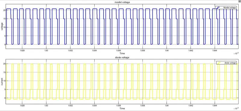
Diode and mosfet voltage:
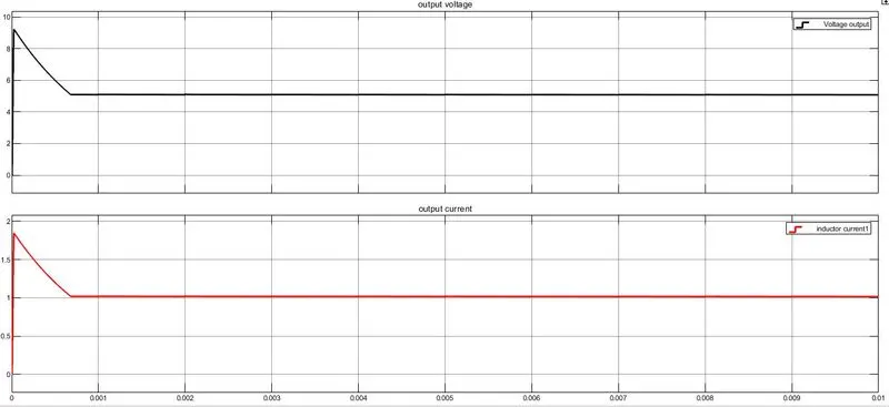
Output voltage and current:
Inductor current:
Infer: The PID controller is giving a desried value of Vout=5V with different current output currents.
3. BOOST CONVERTER IN CONTINUOUS MODE:
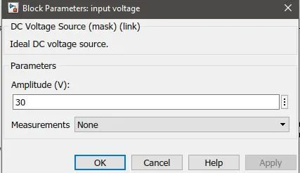
Input voltage=30V,
output voltage=40V;
Fs=100Khz
Vo/Vin=1/1-D;
40/20=1/1-D;
D=0.5;
Power= 600W;
Iout=Pout/Vout=600/40=15A
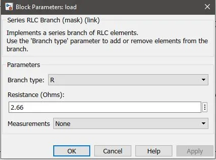
R=Vout^/Pout=40^2/600=2.66
Il=IR/(1-D)=15/(1-0.5)=30A;
L=Vin*D/(Fs*ripple current)
assume ripple current<40%.
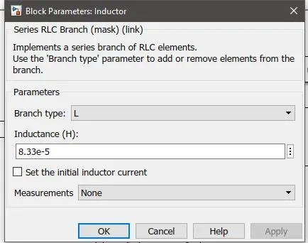
L=20*0.5/(100k*0.4*30)=8.33uH;
ripple voltage 5%.
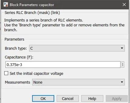
C=D/R*Fs*ripple voltage =o.5/2.66*100k*0.05=0.375mF
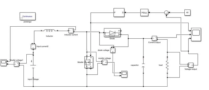
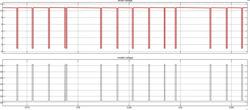
diode and mosfet voltages:
Pulse generator:

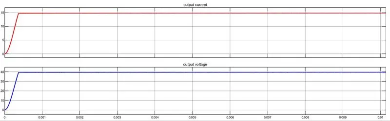
output voltage and current graph: The output voltage is exactly 40V and output current is 15A.
case 2: R=5ohm
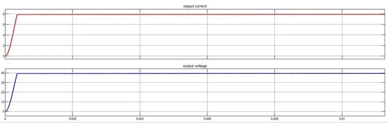
the output graph is shown and the value output current and voltage is 40V and 8A.
infer: we can see exactly the desired output of voltage 40V is achieved.