Project 2
1. Forward converter is a popular switched mode power supply (SMPS) circuit that is used for producing isolated and controlled dc voltage from the unregulated dc input supply. The forward converter, when compared with the
fly-back circuit, is generally more energy efficient and is used for applications requiring little
higher power output.
Given data:
Input voltage: 45 – 60 v
• Output voltage: 3 V
• Output current: 100A
• Efficiency > 85%
Solution:
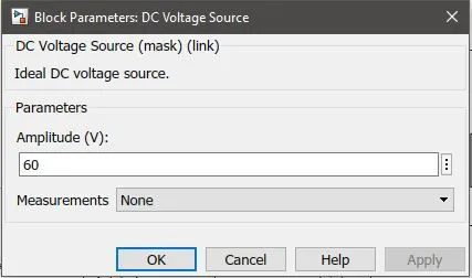
We will be taking Vin=60V ( the upper limit of the range);
Fs=200Khz;
D=50%;
Vout/vin = D*(N2/N1)
3/60*0..5 = N2/N1;
1/10=N2/N1
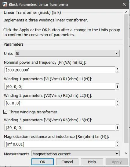
so, lets assume N1=100 , N2= 10
Now, putting the condition
D(1+N3/N1)<1; N3/N1<1, N1=100,N3=30;
P=Vout*Iout=3*100=300W;
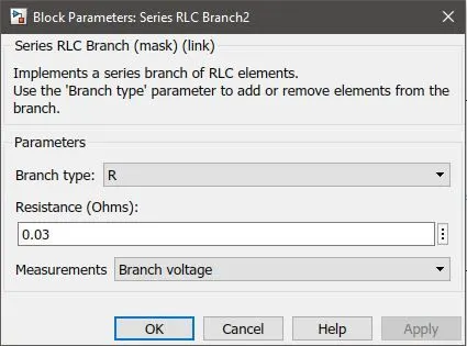
R=V^2/P= 3^3/300=0.03ohm;
Il=Iout=100A;
Assuming ripple current < 40%;
ripple current=0.4*100=40A
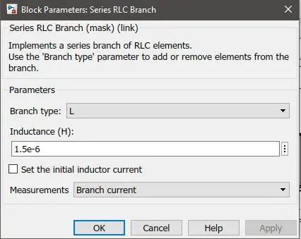
L=Vout*(1-D)/Fs*ripple current = 3*(1-0.5)/20000*40 = 1.5e-6H;
ripple voltage/voltage = 0.05;<5%
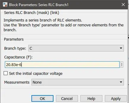
C=1-D/8*L*Fs^2*(ripple voltage/voltage) = 1-0.5/8*(20000^2)*1.5e-6*0.05=20.84uF;
Thus the parameters of passive elements are, R=0.03,L=1.5e-6H,C=20.83e-6F;
inputparameters
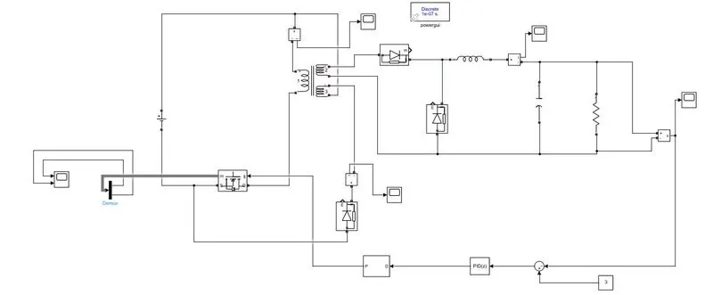
case1: we will be using single phase system without PID controller:
D=50%
The above graph is of Input Current.
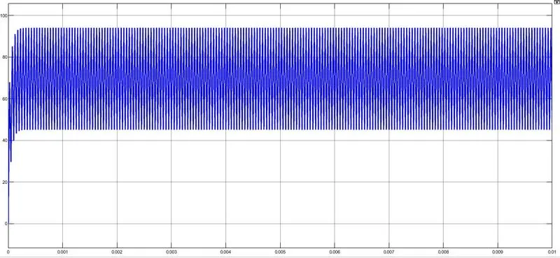
The above graph is of output current. The output current desired value was 100A, but we can clearly see that our system has failed to reach 100A.and also the range is from 43A-90A. this is a huge ripple which is not desrirable.
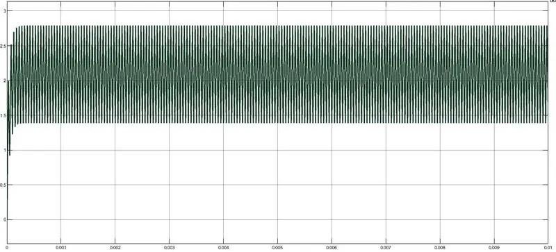
The above graph is of output Voltage. The output voltage desired value was 3V, but we can clearly see that our system has failed to reach 3v.and also the range is from 1.4V-2.7V. this is a huge ripple which is not desrirable.
case 2: Single phase fprward converter with PID controller:
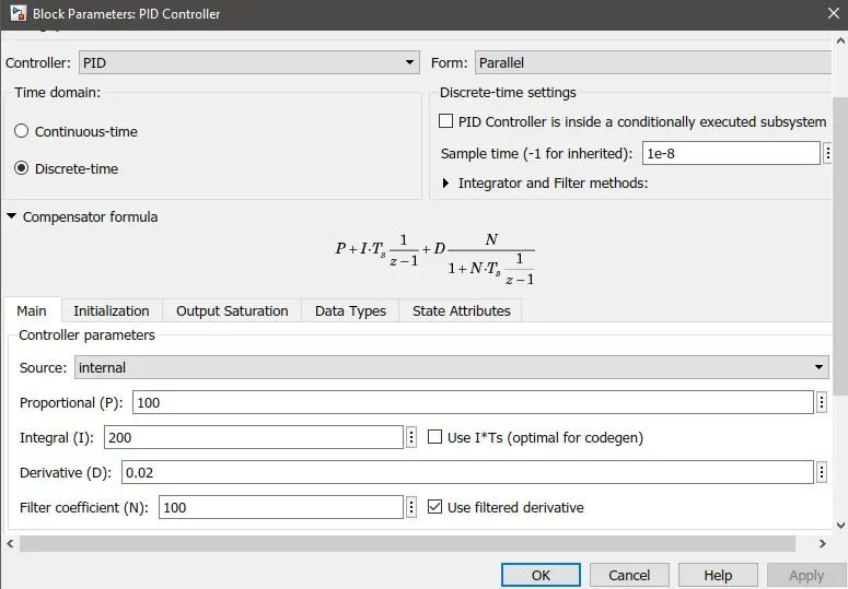
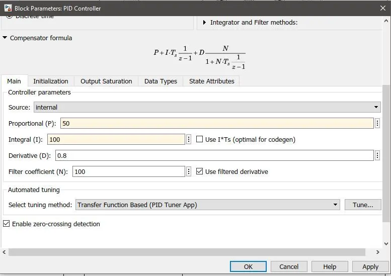
Above are the pid controller parameters.
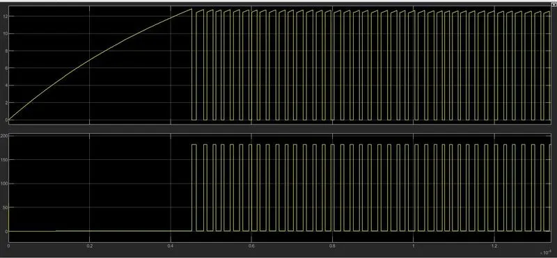
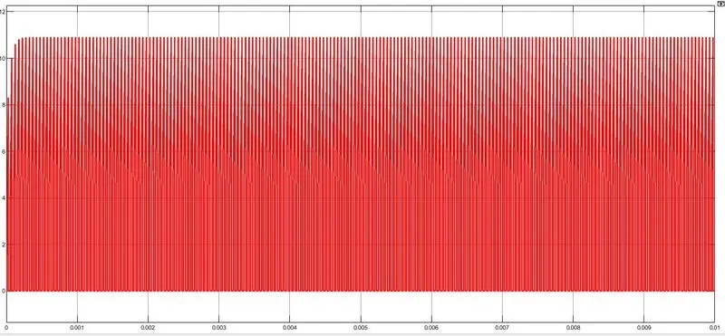
The above on is of input current graph.Due to MOSFET switching the graph is in this manner. The range of input current is from 0-10A. the average input current we can take as 5A.
Below graph is of MOSFET voltage.
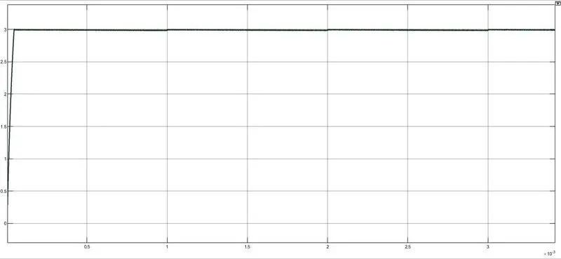
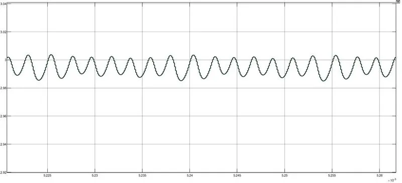
The above graph is of output voltage graph. we can clearly see that it has reached 3V within few mili seconds.
Considering the output ripple voltages, the range of output voltage is from 2.975-3.015V.
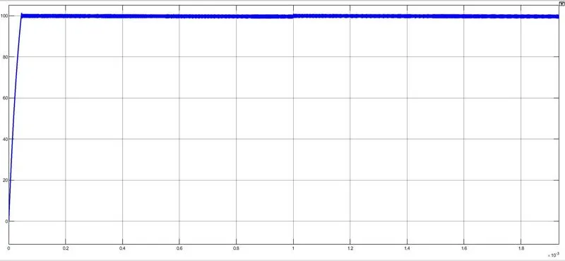
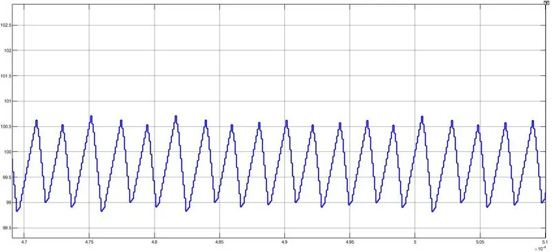
The output current graphs can be seen in the zoomout and zoom in manner. the ripple of current is from 99.7A to 100.7A.
Efficiency:
Efficiency is Pout/Pin:
Pin= Vin*Iin
Vin=60V and Iin= 5A
Pin=300W,
we can clearly see from out output that it has reached 3V and 100A, so we can see 100% efficiency.
But considering ripples also: Iout=99.7+100.7/2= 100.2A
Vout=2.983+3.001/2=2.9922V
Pout=Vout*Iout= 100.2*2.992=299.79W
therefore 99% efficiency is there.
But we will also consider multiphase system and design it for 100% efficiency;
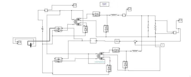
case 3: 2 phase Feedback converter with PID controller
Output graphs
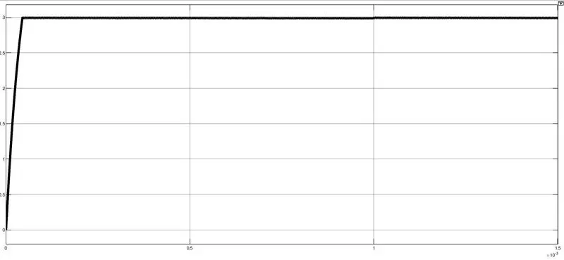
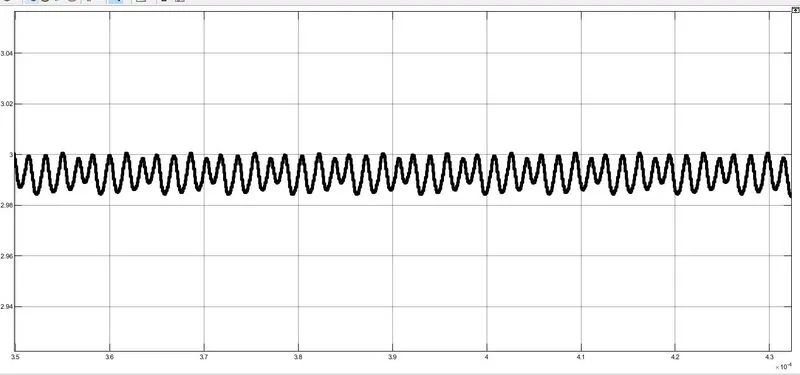
The above graph is of Vout. We can see that 3V s achieved within few mili seconds. The ripple range is from 2.96V-3.018.
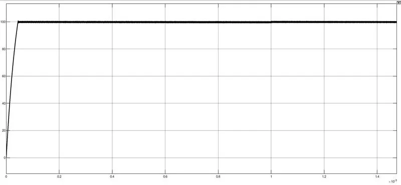
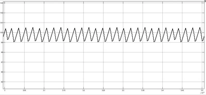
Output current is achieved at 100A. the ripple range is from 99-100.5A.

Input current ranges from 0-10A, so the average input current=5A. and MOSFET voltage is given in below graph.
Efficiency:
Pin=Iin*Vin = 60*5=300;
pout=Vout*Iout=2.989*99.75=298.15W
efficiency=Pout/pin*100=98%.
Thus i have designed both single and multiphase system with highest efficiency.