Project - Position control of mass spring damper system
1) To obtain the transfer function of a mass spring damper system and use it in the model. And to add a PID controller (to adjust the force on mass) so that its position follows a reference signal.
Given: m = 3.6 kg; k = 400 N/m; c = 100 Ns/m;
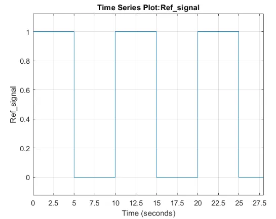
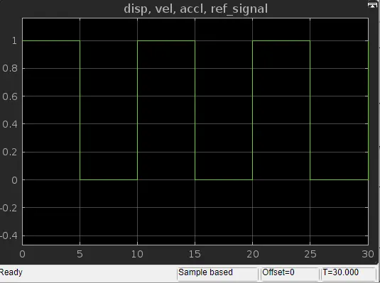
The reference signal is shown in the following figure.
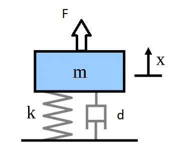
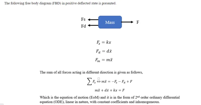
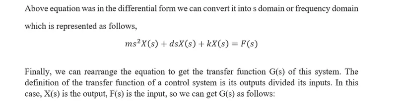
Solution: The differential equation of a mass spring damper system which represents the dynamic behavior of the physical system is illustrated and represented as follows:
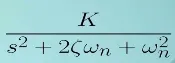
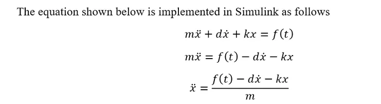
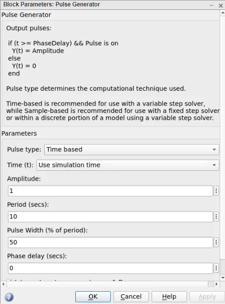
The below image shows that the Pulse Generator block parameter has been set as per the reference signal given in the problem statement which is also a forcing function of the mass-spring-damper system.
The image below is the scope block output signal as per the problem definition.
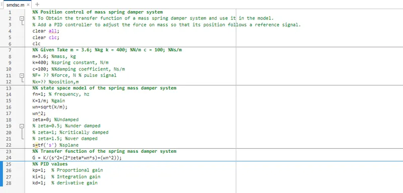
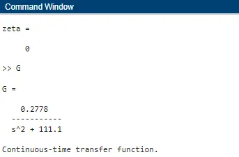
The below image shows the script file which defines the various parameters to simulate the mass-spring-damper system.
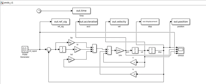
The below image shows the Simulink model built to represent the physical system using various blocks like pulse generator, add, integrator, gain, clock, to workspace, scope, etc. All the blocks have been connected to form a replica of a physical mass spring damper system by connecting the blocks and simulating the same for its response. Also, the PID controller has been designed to control the position of the mass during the dynamic behavior of the system.
The system response has been analyzed for the below cases:
i) when zeta=0;
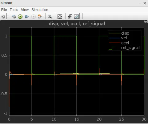
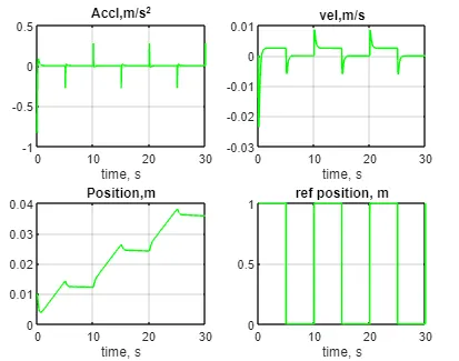
The below image shows the response of the system at various locations like acceleration, velocity, and displacement along with the signal reference. And PID controller design values are assigned as kp=1; ki=1; kd=1.
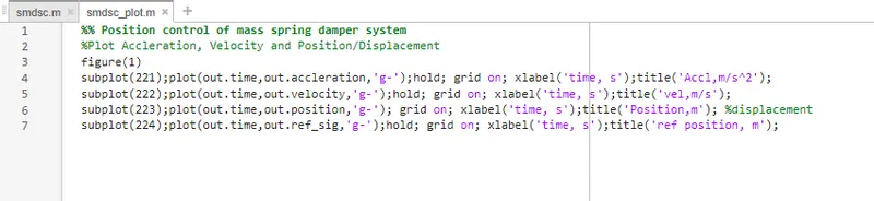
The below image represents the Matlab script written to plot the response of a mass spring damper system at position, velocity, and acceleration. Along with the reference signal.
ii) when zeta=0; kp=3; ki=100; kd=20
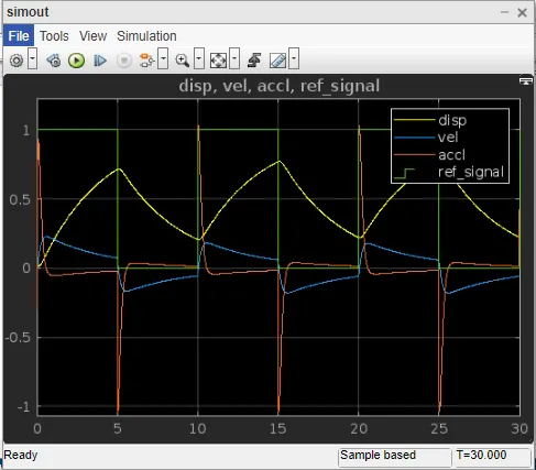
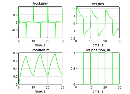
iii) when zeta=0; kp=100; ki=1300; kd=45
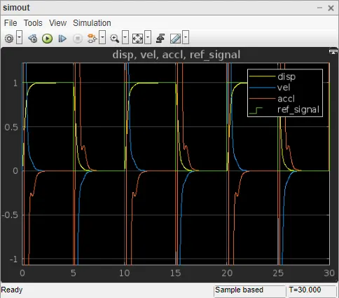
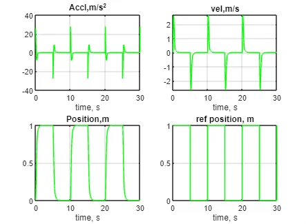
The above figure shows that the spring mass damper system is following the reference signal (as per the problem statement) for the above conditions set like zeta=0; kp=100; ki=1300; and kd=45.
If any further deviation in the above set values the response of the system is unstable and was not following the set signal path.
________________________________________________________________________________________
Command window
kp =
5
kp =
3
ki =
5
kd =
5
kd =
3
ki =
3
ki =
10
ki =
100
kd =
100
kd =
20
kp =
10
kp =
6
kp =
3
Current plot held
Current plot held
ki =
80
ki =
200
ki =
250
kd =
40
kp =
10
ki =
300
ki =
500
ki =
700
ki =
800
kp =
20
kd =
80
kd =
50
kp =
20
kp =
40
kp =
80
ki =
1000
ki =
1100
kp =
120
kd =
100
kd =
60
kd =
70
kd =
65
kd =
60
ki =
1200
kp =
5
kd =
50
kd =
25
kd =
30
kd =
35
kd =
40
kp =
4
kp =
3
kd =
45
kp =
1
kp =
0
kp =
100
ki =
1300
Current plot held
Current plot held
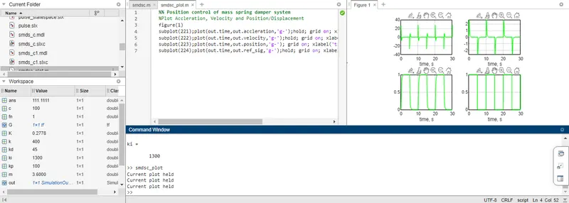
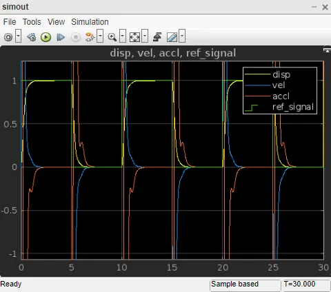
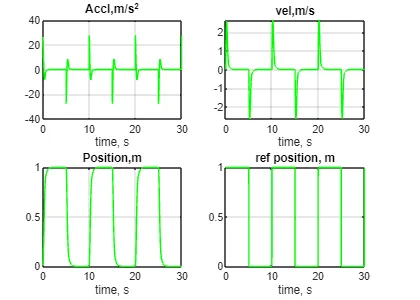
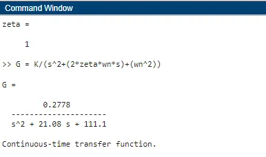
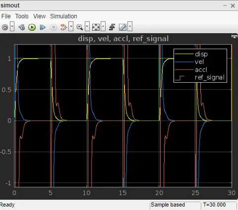
Further, the response of the mass-spring-damper system was analyzed for various values of zeta.
i) zeta = 0.5,
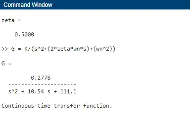
ii) zeta=1
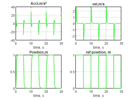
iii) zeta=1.5
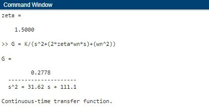
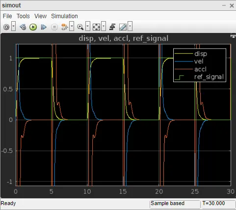
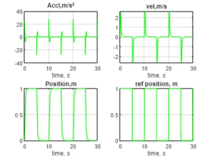
From the above results, it can be said that the mass-spring-damper system has been built using Simulink blocks by applying the transfer function equation to the model and also designed a position controller by adding a PID controller to the mass-spring-damper system to adjust the force on the mass and to follow the reference signal.
Obtained results have been validated to all the values of zeta undamped/under-damped/ overdamped/ critically damped conditions. In all the above conditions the force on the mass is following the reference signal. And also the PID controller design values are also optimized manually to meet the set conditions.