Project - Position control of mass spring damper system
PROJECT
Obtain the transfer function of a mass spring damper system and use it in the model. Add a PID controller to adjust the force on mass so that its position follows a reference signal.
Take m = 3.6; %kg k = 400; %N/m c = 100; %Ns/m
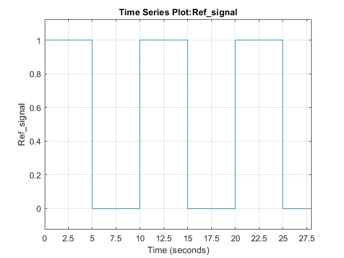
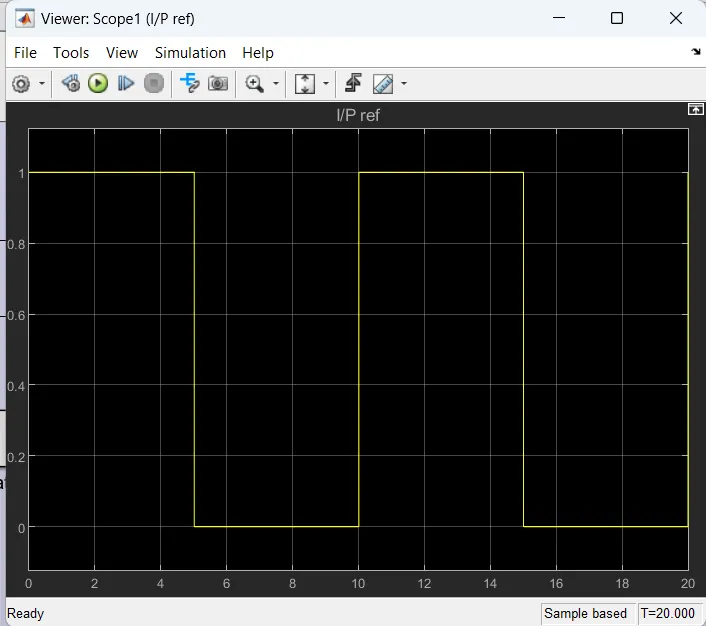
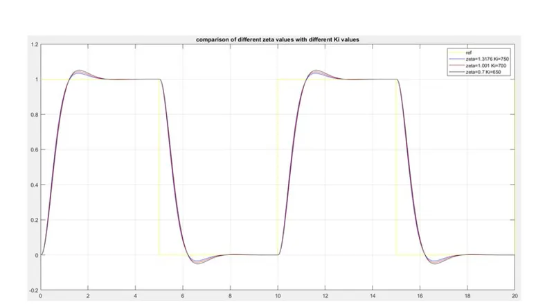
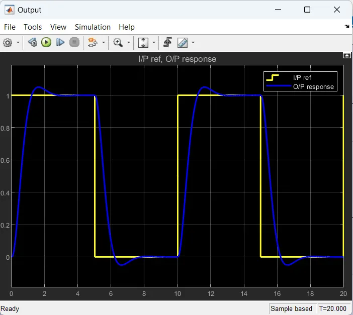
The reference signal is shown in the following figure.
Aim
A mass spring damper system's transfer function should be obtained and used in the model. Put a PID controller in place to modify the force acting on the mass such that its location complies with the reference signal.
Objective
- Spring mass damper systmem
The discrete mass nodes in the mass-spring-damper model are dispersed throughout an object and connected by a network of springs and dampers. This model works well for simulating objects with detailed material characteristics like viscoelasticity and nonlinearity. Simulations of these models can be performed using programmes like MATLAB. These systems have uses in computer graphics and animation in addition to engineering simulation.
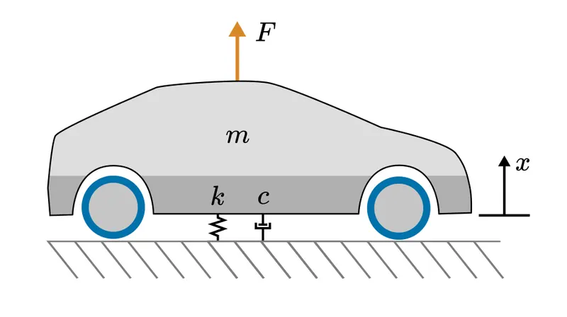
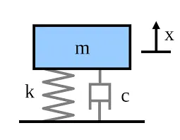
Consider the simple spring mass damper system
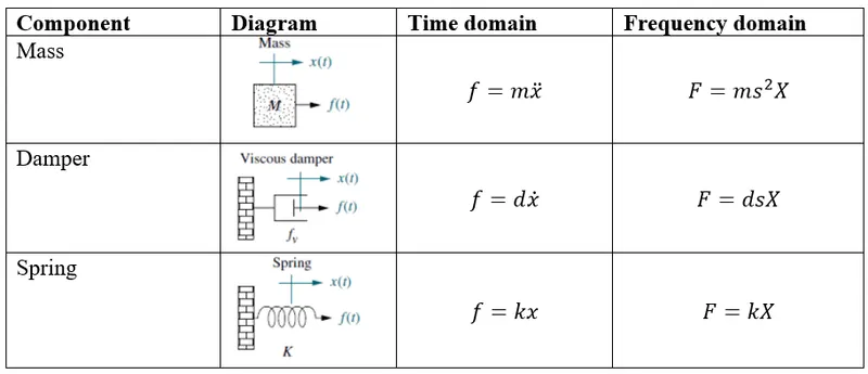
Consider the following equation
`mddotx+ c dotx+kx=f`
`ms^2X(s)+csX(s)+kX(s)=F(s)`
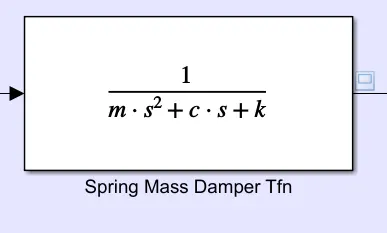
`G(s)=(X(s))/(F(s))=1/(ms^2+cs+k)`
- PID Controller
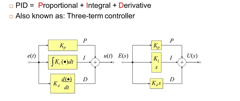
A feedback-based control loop mechanism known as a proportional-integral-derivative controller (PID controller or three-term controller) is frequently employed in industrial control systems and a number of other applications that call for constantly modulated control.
PID systems automatically rectify a control function with accuracy and responsiveness. A common example is the cruise control on a car, which would slow down if engine power was applied continuously while it ascended a slope. By gradually increasing the engine's power output, the controller's PID algorithm returns the measured speed to the target speed with little delay or overshoot.PID was originally theoretically analysed and used in practise in the early 1920s when automatic ship steering systems were being developed. The manufacturing sector employed it for automatic process control, and it was widely used in pneumatic and later electronic controllers. The PID principle is now used in all applications that call for precise and effective automatic control.
From the question we have some datas
The given conditions are
mass m= 3.6 kg
Damping coefficient c =100Ns/m
Spring constant k = 400Nm/s
In order to develope the matlab model we need to create a script for mathematical modelling
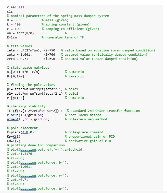
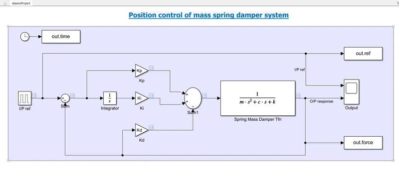
With the help of the script the model is developed and which is shown below
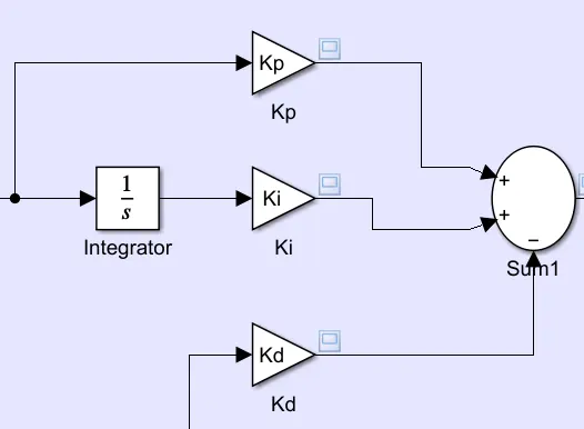
PID controll area for adjusting values
- The integrator block and output of the refrence signal feed the input for the integral gain Ki. To record the response with a reference signal, the Ki's initial response was set to zero.
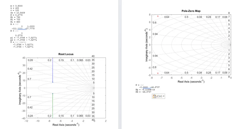
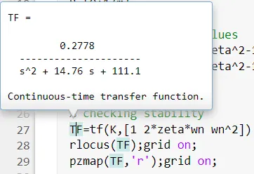
- By running a Matlab file, the PID gains, such as Kp and Kd values, are calculated, and those values are then changed in the system.
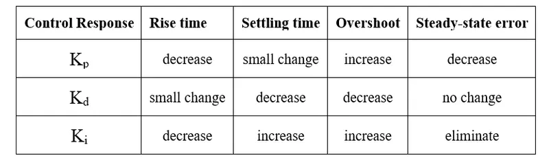
- To provide stable and responsive control of a system, the proportional, integral, and derivative gains (Kp, Ki, and Kd) of a PID controller must be set to the proper levels. Since the selection process depends on the system's dynamics, input/output characteristics, and performance needs, there is no one universal strategy for choosing the best PID gains.
Output datas according to the Script file, Here we got pole zero map & rootlocus
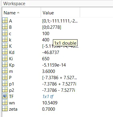
Workspace Values
Input Refference
Using a pulse generator with an amplitude of 1 and a period of 10 seconds, as illustrated in the picture below, the input refrence signal is inputted through the system.

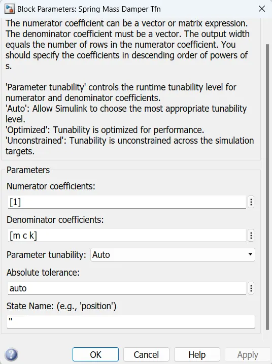
The transfer function block represent the spring mass damper system
Conclusion
- Start with small Kp, Ki, and Kd values and progressively increase them until you get the appropriate reaction. The "trial and error" approach is this.
- To find the PID improvements that will result in the highest performance, first access the system's dynamics and behaviour using mathematical models or simulations.
- To determine the ideal PID gains, use tuning techniques like the Ziegler-Nichols approach or the Cohen-Coon method. In order to identify the proper gains, these techniques entail introducing a step input into the system and monitoring its reaction.
- To calculate the ideal gains depending on the characteristics of the system, use heuristic rules of thumb. For instance, a rapid and stable system might need a high Kp, whereas a sluggish and slow system might need a high Ki.
- In summary, exact Kp, Ki, and Kd value selection in a PID controller is essential for achieving stable and responsive control. The best gains can be chosen using a variety of techniques, including mathematical modelling, tuning techniques, and heuristic principles. It's vital to remember that there is no set procedure for choosing the best PID gains; instead, the process is dependent on the dynamics of the system and its performance needs.
Refferences