Project - Position control of mass spring damper system
Aim- To model a mass spring damper system and design a PID controller to adjust the force applied to the mass so that its position can track a reference signal.
Introduction- The project involves obtaining the transfer function of the system, analyzing its response characteristics, and designing a PID controller using appropriate tuning methods. The ultimate goal is to simulate the closed-loop system and verify that the controller is able to accurately control the position of the mass in response to the reference signal.
Calculations-
m=3.6Kg
k=400N/m
c=100Ns/m
Diagram of spring-mass-damper system
The Equation representing the spring-mass-damper system-
`f(t)=m\ddotx+c\dotx+kx`
Laplace's transform of the above equation is-
`F(s)=ms^2X(s)+csX(s)+kX(s)`
`F(s)=X(s)[ms^2+cs+k]`
The transfer function for spring-mass-damper is given by-
`G(s)=\frac{X(s)}{F(s)}=\frac{1}{ms^2+cs+k}`
State-space system matrices are
`A=[[0,1],[-k/m,-c/m]]`
`B=[[0],[1/m]]`
`C=[[1,0]]`
`D=[0]`
The roots of the denominator polynomial are
`p1=-\zeta\omega_n+\omega_n\sqrt(\zeta^2-1)`
`p2=-\zeta\omega_n-\omega_n\sqrt(\zeta^2-1)`
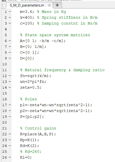
The control gains Kp and Kd can be determined using the place command in MATLAB.
Procedure-
Modelling of the spring-mass-damper system using control gains-
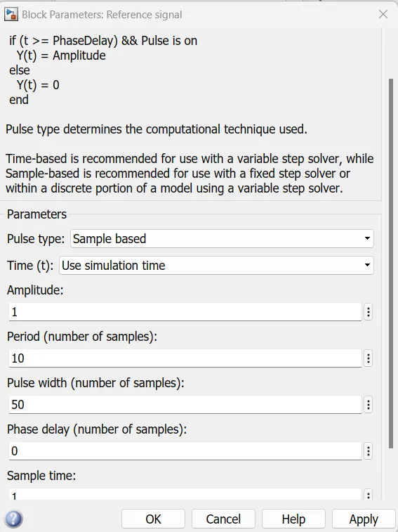
1) Creating the reference signal using a pulse wave generator block
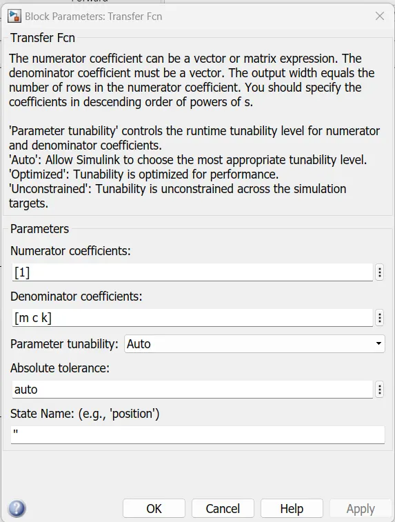
2) Creating a transfer function block with system parameters
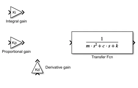
3) Creating gain blocks
Creating gain blocks with the control gains
4) Adding a summing junction to add the gains
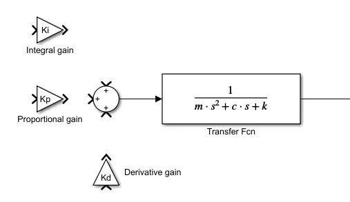
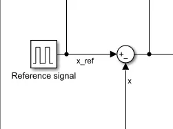
5) Adding a summing junction to subtract the output signal from the reference signal.
6) Connecting all the blocks 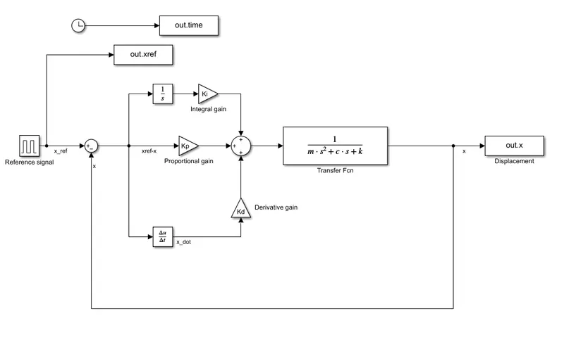
7) Tuning the values of the control gains to get the best tracking response
i)Tuning the values of the integral gain-
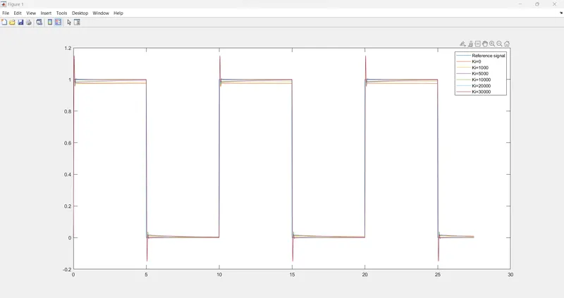
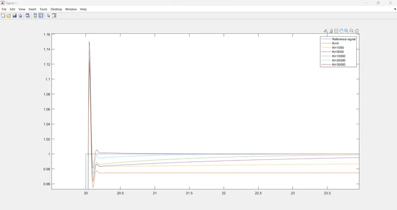
Ki=15000-30000 .......Range
Ki=18000
There are overshoots present in the tracking response.
To eliminate these overshoots we can tune the derivative gain
ii)Tuning the values of the derivative gain-
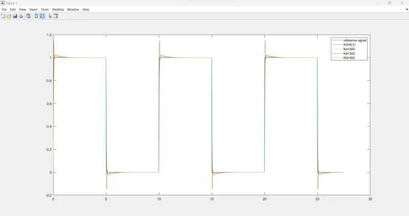
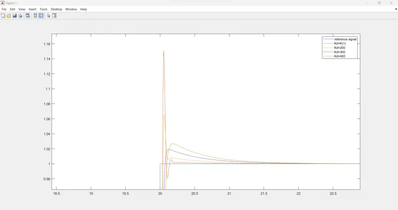
Kd=200-300 .......Range
Kd=300
Results-
With the control gains Ki=18000, Kp=K(1), and Kd=300 for an underdamped system(`\zeta=0.5`) we can get the best response with a fast settling time and minimal overshoot.
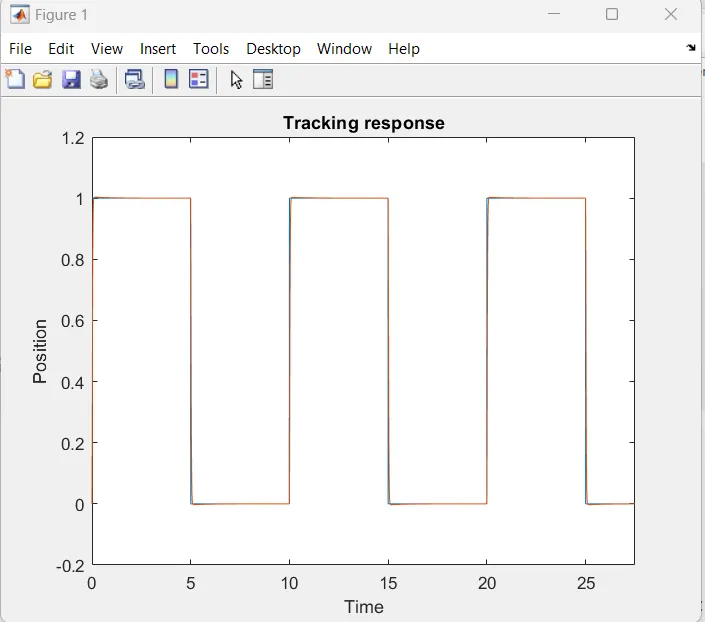
Conclusion- In conclusion, we have successfully modelled a mass spring damper system and designed a PID controller to control its position in response to a reference signal. We first obtained the transfer function of the system and analyzed its response characteristics, such as the natural frequency, damping ratio, and steady-state error. Using appropriate tuning methods, we designed a PID controller and simulated the closed-loop system to verify its performance.