Project - Analysis of a practical automotive wiring circuit
1. The elements in the automotive wiring can be classified as follows:
- Power Source
- Conductors and safety devices
- Load
- Switches and regulators
Major elements in the automotive wiring diagram
| Power Source | Conductors and Safety devices | Load | Switches and regulator |
|---|---|---|---|
|
|
|
|
2.
- BATTERY
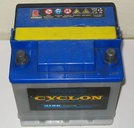 |
The automotive battey is a rechargable battery used to start the vehicle. The battery provides the energy for the starting motor to crank the engine at the startup from idle condition. Once the ignition starts, the battery energy is then used to supply electricity to other auxiliary loads in the system such as lamps and indicator lights. Due to this automotive battieries are also know as 'SLI' battery, where SLI stands for starting, lighting and ignition |
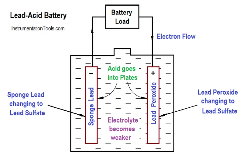
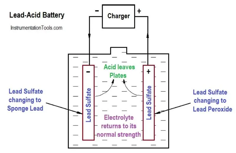
| Modern SLI batteries are lead-acid battery having either 6 cells conncted in series to give a 12 V nominal output or 12 cells connected in series to give a 24 V nominal voltage output. In each cell, the lead electrodes are immersed in sulfuric acid. The anodes are spongy lead metal and the cathodes are lead impregnated with lead oxide. | 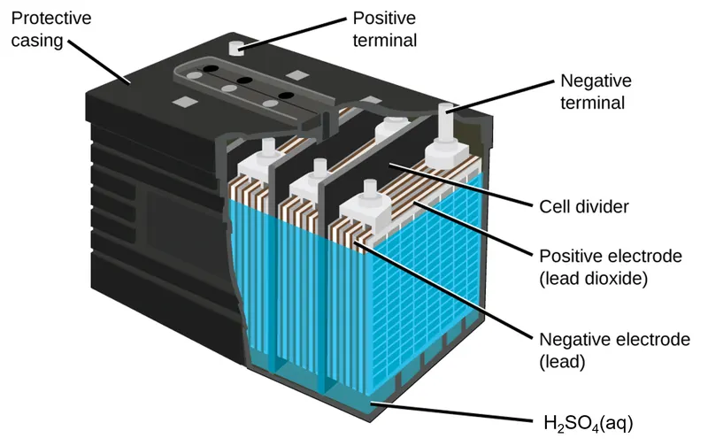 |
|
Discharging Charging
|
|
|
Overall cell reaction during discharge `PbO_2+Pb+2H_2SO_4rarr2PbSO_4+2H_2O` |
Overall cell reaction during charging `PbO_2+Pb+2H_2So_4larr2PbSO_4+2H_2O` |
| As the battery is discharged, a powder of PbSO4 forms on the electrodes. When a lead-acid battery is recharged by a car’s alternator, electrons are forced to flow in the opposite direction which reverses the reactions at anode and cathode, in other words, the cell undergoes electrolysis reactions to replenish the substances that have reacted away. | 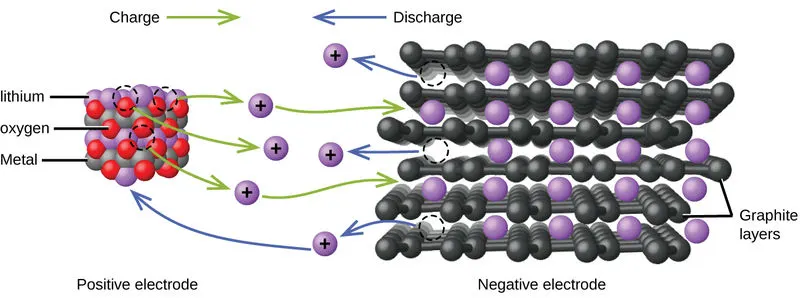 |
- STARTER
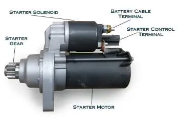 |
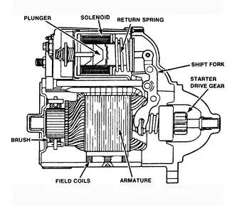
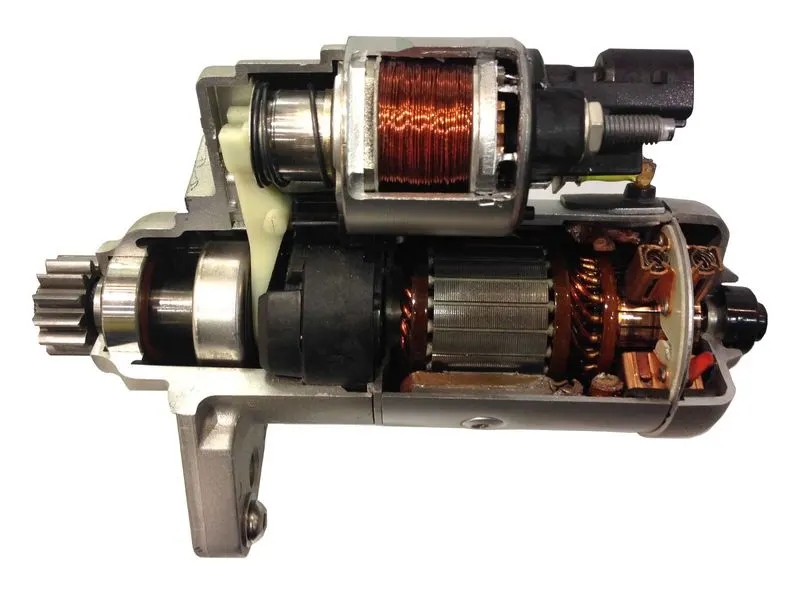
A starter is an electrical device used to crank the engine during startup. A starter is required since IC engines cannot start on its own , and requires some intial torque to be given into the crankshaft through the flywheel. When the ignition switch is turned on, the electromagnet inside the body engages & pushes out a rod to which the pinion is attached. The pinion meets the flywheel and the starter motor turns. This spins the engine over, sucking in air (as well as fuel). As the engine turns over, the starter motor disengages, and the electromagnet stops. The rod retracts into the starter motor once more, taking the pinion out of contact with the flywheel and preventing potential damage. |
|
The componenets of starter are:
|
|
|
|
|
- FUSE (AUTOMOTIVE)
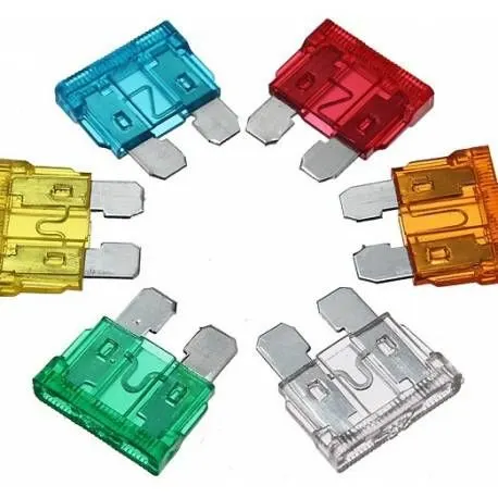 |
Car fuses are components designed to protect electrical wiring in cars and vehicles. They offer protection against overcurrent and short-circuiting, disconnecting the circuit if they detect a potentially dangerous level of current. Most modern car fuses are blade type fuse. The various automotive fuses have a similar design, characterised by a coloured plastic body and two prongs that slot into the socket. They can be mounted in fuse blocks, fuse clips, or fuse holders, depending on the application. The fuses consist of a wire conductor that breaks when the current exceeds the ampere limit. The ampere limit is usually defined on each fuse along with different colour codes. Placing the right fuse with the correct ampere is integral for protection. |
|
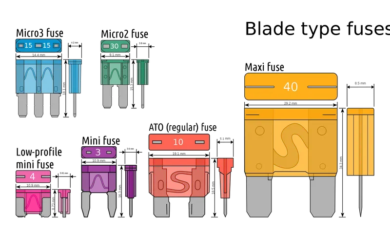
Automotive fuses has 6 variations based on the dimension of the component.
|
 |
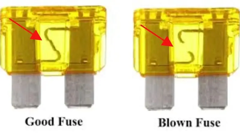 |
The various reasons due to which the fuses gets blown are:
|
3. Given the load current = 10 A
For selecting the fuse, fusing factor can be selected anywhere between 1.2 to 2
Selecting fusing factor, f = 1.5 ( 50 % more than the load current )
Fuse current rating = Load current x fusing factor = 10 x 1.5 = 15 A
4. Given, the power rating of load = 500 W
i.e in 1 hour, the energy consumed by the load = 500 VAh
Assuming, the load must run for 48 hours continuously
Then total energy consumed by the load = 500 x 48 = 24000 VAh
Taking, battery voltage, V = 12 V
Battery capacity x Battery run time = Total energy consumed by the load
Then Battery capacity = 24000 / 12 = 2000 Ah
5. Elements connected in parallel
- Tail stop lamps to each other
- Sealed Beams to each other
The lamps are connected in parallel in electrical circuit. This is due to the fact that, if they are connected in series, while passing thorugh the first lamp, the current encounters a resistance and while passing through the next, the resistance doubles up in the entire circuit. This causes the current through the circuit to get halved leading to the feeble glow of the bulb. Hence such componenents are always connected in parallel making the current to encounter resistance only once.
6. Elements connected in series
- gas tank unit and fuel gauge
- battery and ammeter
The gas tank unit and fuel gauge are connected in series to enhance the 'communication' between the two elements. Here the changes in the fluid level can lead to a resistance change in the circuit. This resistance change can be linked directly to the gauge needle for graphical representation on the vehicle dashboard. Hence, since resistance is the controlling factor, they are connected in series. The battery and ammeter are always connected in series inorder to measure the current through the circuit.