Study on BAJA All Terarin Vehicle Model.
Q: Carry out a system-level simulation of an all-terrain vehicle. Prepare a technical report explaining the model properties & comments on the results.
A: Aim: To study and create a report on BAJA ATV model and carry out system level simulation on it.
ATV: These are known as All-Terrain vehicles or quad, defined by ANSI. These vehicles travels on low pressure of non-pneumatic tires, with a seat that is straddled by the operator, along with the handle bars for steering control. These are also known for off-road vehicles.
Uses: passenger, loading etc.
Applications: ATV's are used in various industries, including sports, entertainment, agriculture, military, defense etc.
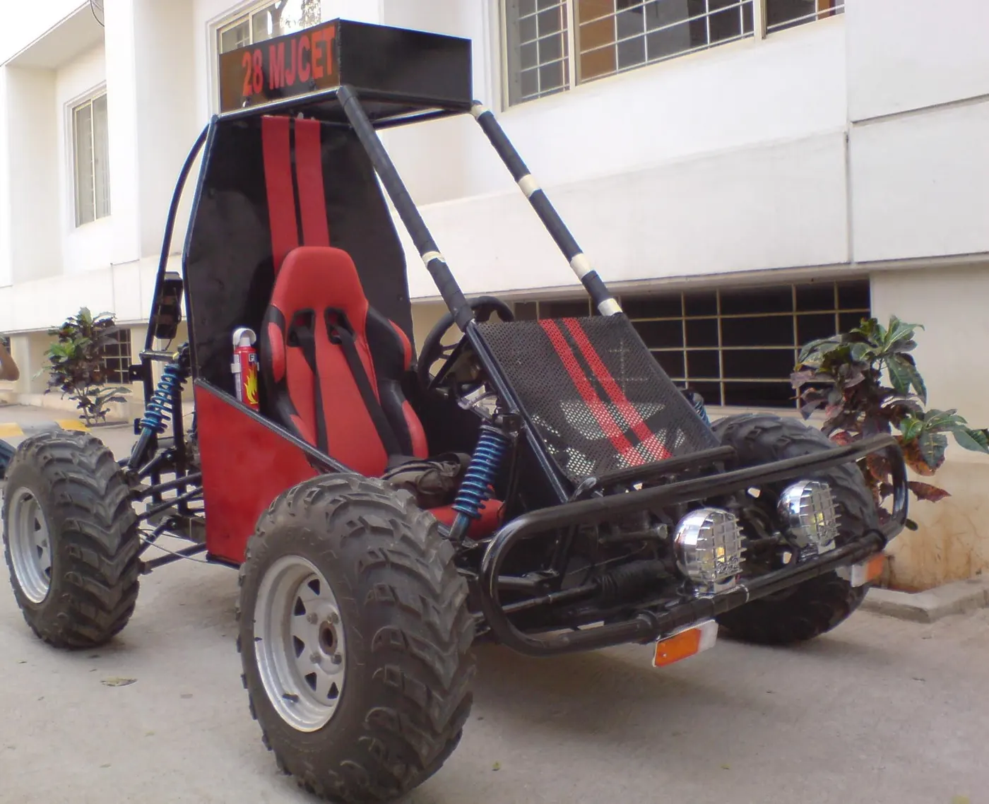
BAJA ATV: ATV's are created accorrding to the rulebook provided by the SAE Baja. It is a even for students conducted by Society of Automotive Engineers.
Below is the reference image for BAJA ATV
CVT: It means Continuously Variable Transmission. It is a automatic transmission that can change seamless through a continuous range of gear ratios. The contrasts with other transmission that provide a limited no.of gears ratios in fixed steps. The flexibility of a CVT with suitable control may allow the engine to operate at constant RPM, while the vehicle moves at varying speeds.
This type of transmission is used in automobiles, tractors, motor scooters, snow mobiles and Earth moving vehicles.
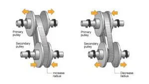
There are so many types of CVT's. Common type of CVT is pulley type.
It consists of two pulleys, primary and secondary, which are varied for speed. One is driven shaft and another is driver shaft.
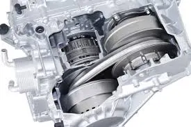
CVT used in engines are shown in below image.
Blocks used in BAJA ATV model:
- Generic Engine: The Generic Engine block represents a general internal combustion engine. Speed-power and speed-torque parameterizations are provided.
Ports:
B Rotational conserving port representing the engine block F Rotational Conserving port representing the engine crankshaft T Physical signal input port specifying the normalized engine throttle level P Physical signal output port reporting the instantaneous engine power, in W FC Physical signal output port reporting the fuel consumption rate, in kg/s 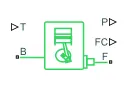
- Simple gear: The Simple Gear block represents a gearbox that constrains the connected driveline axes of the base gear, B, and the follower gear, F, to corotate with a fixed ratio that you specify.

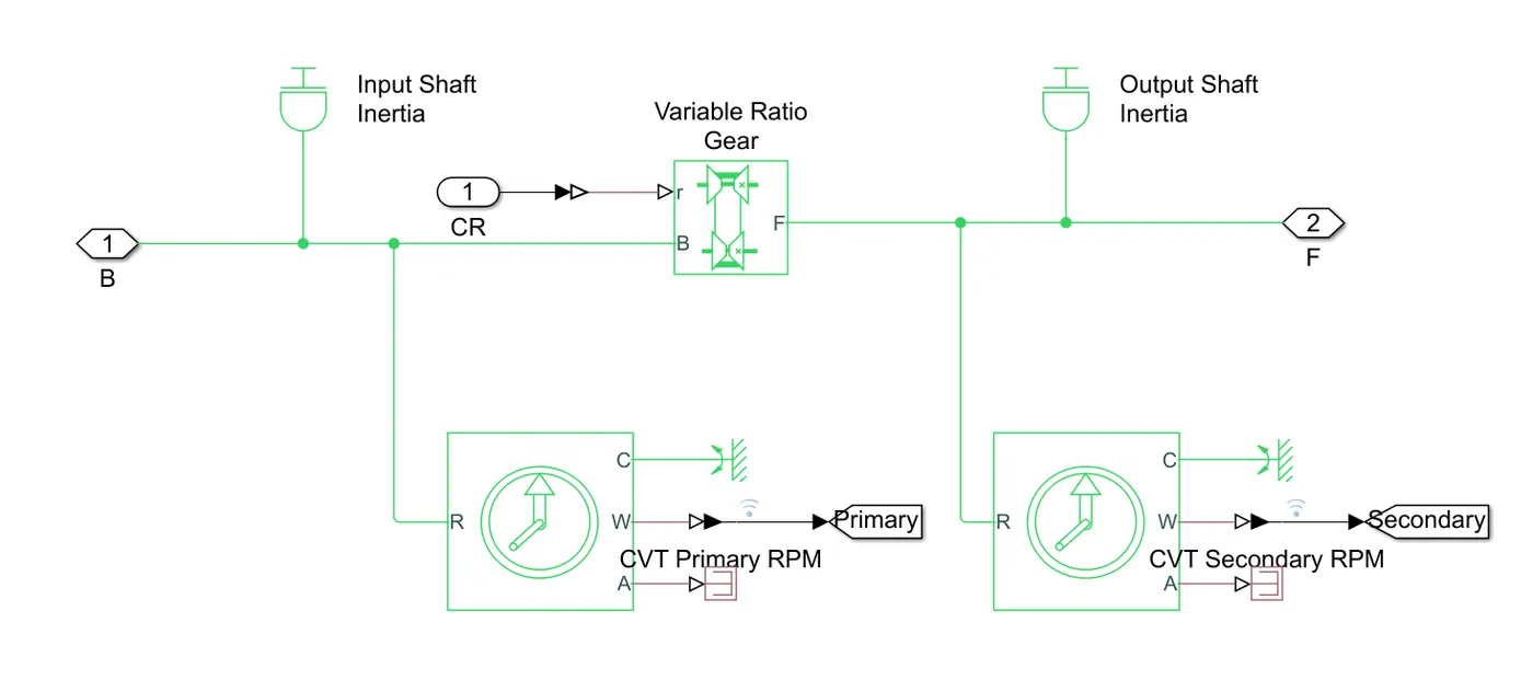
- Ideal rotational motion sensor: The Ideal Rotational Motion Sensor block represents an ideal mechanical rotational motion sensor, that is, a device that converts an across variable measured between two mechanical rotational nodes into a control signal proportional to angular velocity or angle. Connections R and C are mechanical rotational conserving ports that connect the block to the nodes whose motion is being monitored. Connections W and A are physical signal output ports for velocity and angular displacement, respectively.

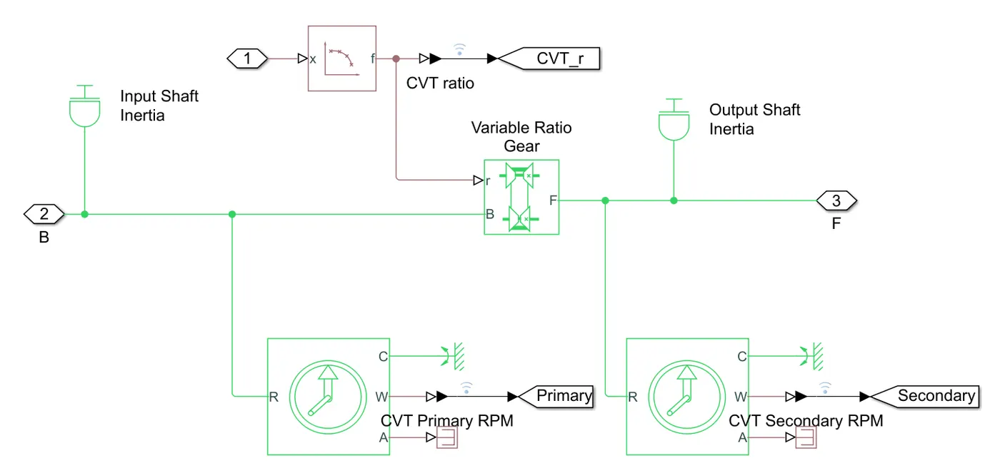
- Variable ratio gear: The Variable Ratio Transmission block represents a gearbox that dynamically transfers motion and torque between the two connected driveshaft axes, base and follower. B is base and F is follower and 'r' is avariable transimission ratio.

- Inertia block: The Inertia block represents an ideal mechanical translational inertia.

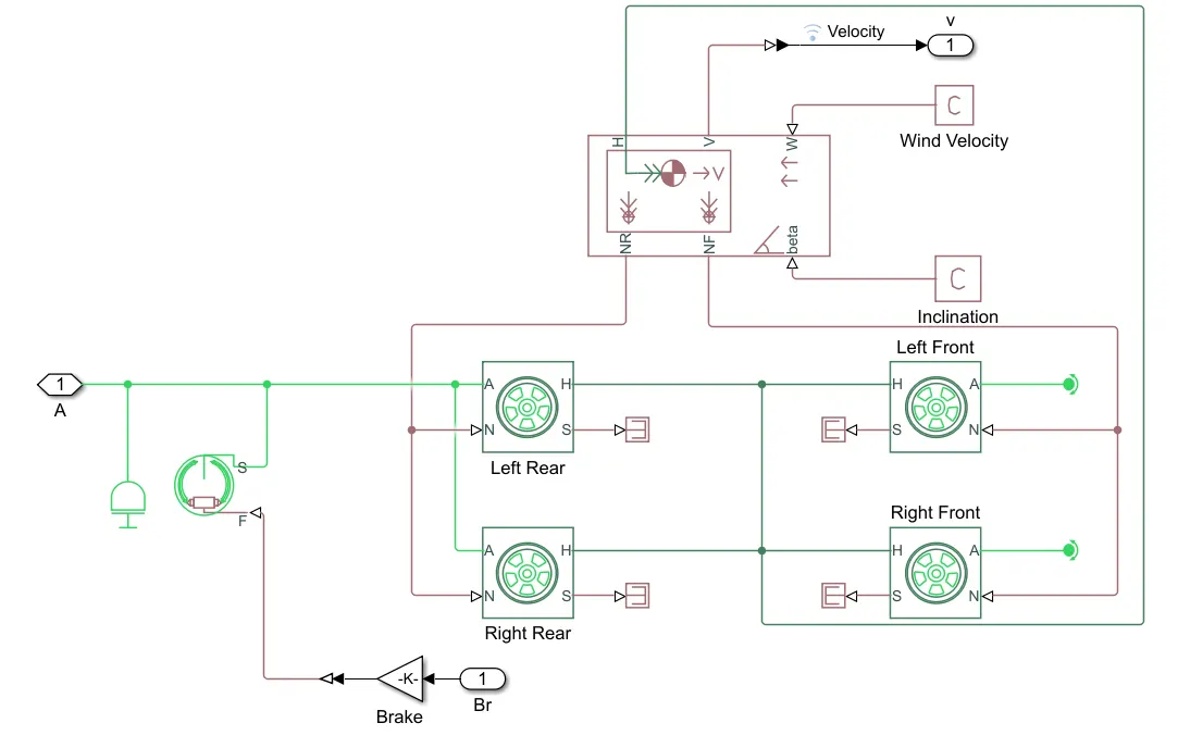
- Double shoe break: The Double-Shoe Brake block represents a frictional brake with two pivoted rigid shoes that press against a rotating drum to produce a braking action. The rigid shoes sit inside or outside the rotating drum in a diametrically opposed configuration. F is physical input port and S is a rotational conserving port with roating drum shaft.

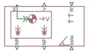
- Vehicle body: The Vehicle Body block represents a two-axle vehicle body in longitudinal motion. The vehicle can have the same or a different number of wheels on each axle. H is a horizantal motion, V is longintudinal velocity in m/s, W is a head wind speed in m/s, beta is road incilantion angle, NR and NF is a normal force of rear and front axle.
BAJA ATV model:
https://in.mathworks.com/matlabcentral/fileexchange/70576-baja-all-terrain-vehicle-atv-model
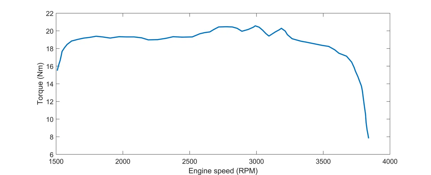
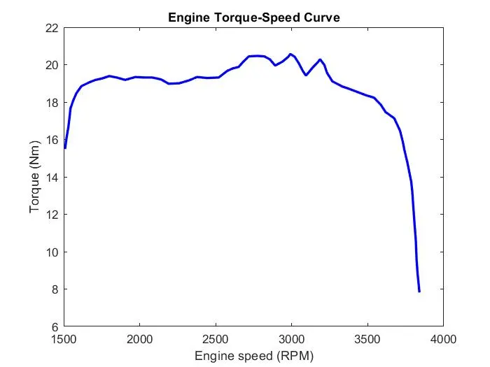
The file includes BAJA ATV model with Continuously Variable Transmission(CVT). These models show how to build an ATV with CVT which is mostly used in BAJA competitions. Simscape and Simscape Driveline have been used to complete the system. The engine data used in the model is provided as an image which shows the Engine Speed (RPM) vs Torque curve.
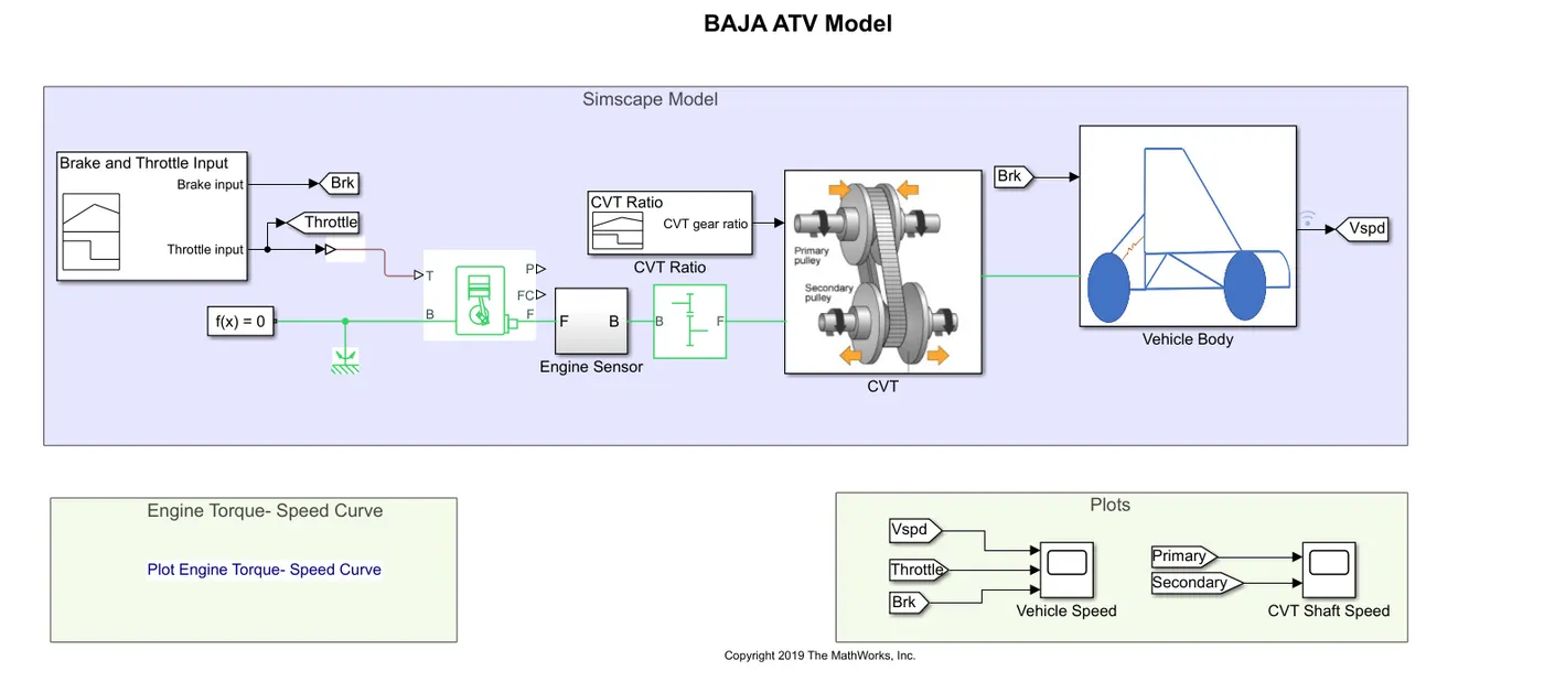
Model 1: BAJAJ ATV MODEL
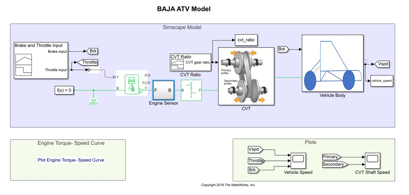
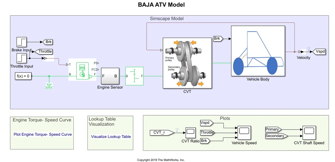
- This model consists of generic engine, engine sensor, simple gear, CVT, vehicle body.
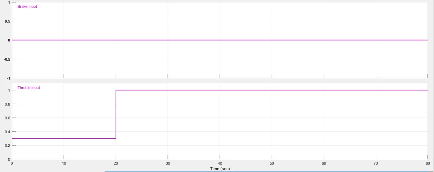
- Signal builder is used for constructing throttle and brake input. Throttle and brake inputs are taken from the workspace and two signals are built. The two physical signals are sent to the generic engine with a converter. For generic engine input is given at the point T.
- The point B is connected to solver configuration with a mechanical rotational reference block for finding the solution.
- In generic engine the initial velocity is given as 2100 rpm with threshold speed limit 100 rpm.
- The output of generic engine F is connected to engine sensor. The output F is a point where the output crank shaft is connected to gearbox in practical.
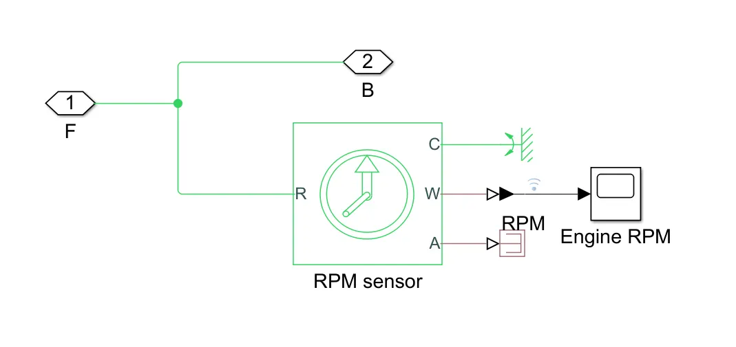
- Engine sensor is used to sense the output of engine. It is a subsystem where RPM sensor is used and also it is connected to the scope.
- From the engine sensor the point B is connected to the simple gear block. The base to teeth ratio is given as 4 with no losses.
- The ouput of simple gear F is connected to CVT subsystem.
- CVT subsystem is consists of ideal rotational motion sensor, variable ratio gear with input and output inertia.
- Gear ratio is 4.
- Ideal rotational motion sensor, senses the output of the simple gear. Another is used after variable ratio gear to sense the output of it. This is used to compare input and output of variable ratio gear.
- The output of CVT is connected to vehicle body subsystem. This subsystem contains double shoe brake, vehicle body and four tires.
- Shoe brakes are used for tires braking and also vehicle body is connected to four tires. Mass is given as 250 kg and with CG distance 1 m and 0.5 m to front and rear axle.
- Frontal area is 0.735482 m^2 and drag coeeficient 1.92.
- The output of the vehicle body is given to scope.
- Two plots are constructed for vehicle speed and CVT shaft speed.
Model:
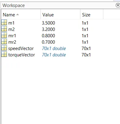
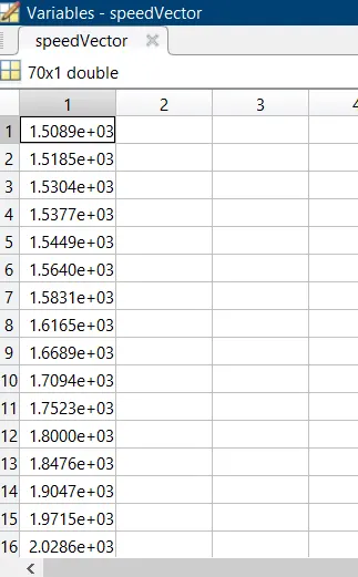
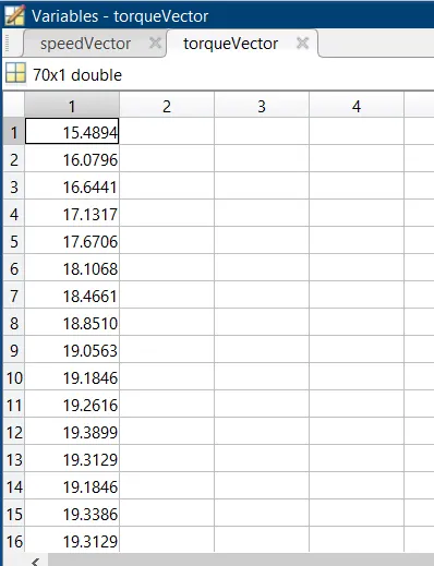
Workspace values: We give values in the workspace and these values are taken for building the signal. Values for m1, m2, mr1, mr2 are given.
Input: Here, we give two types of inputs as brake input and throttle input.
CVT input: Input signal is given for CVT subsystem.
Engine sensor subsystem:
CVT subsystem:
Vehicle body subsystem:
Engine RPM scope:
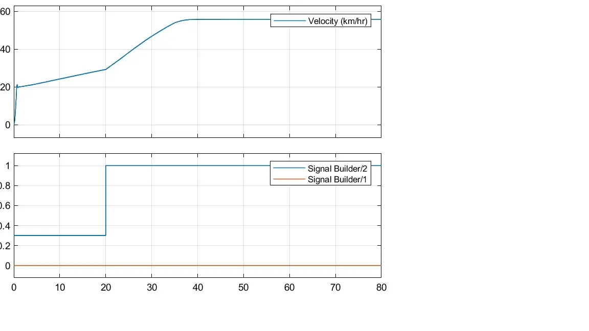
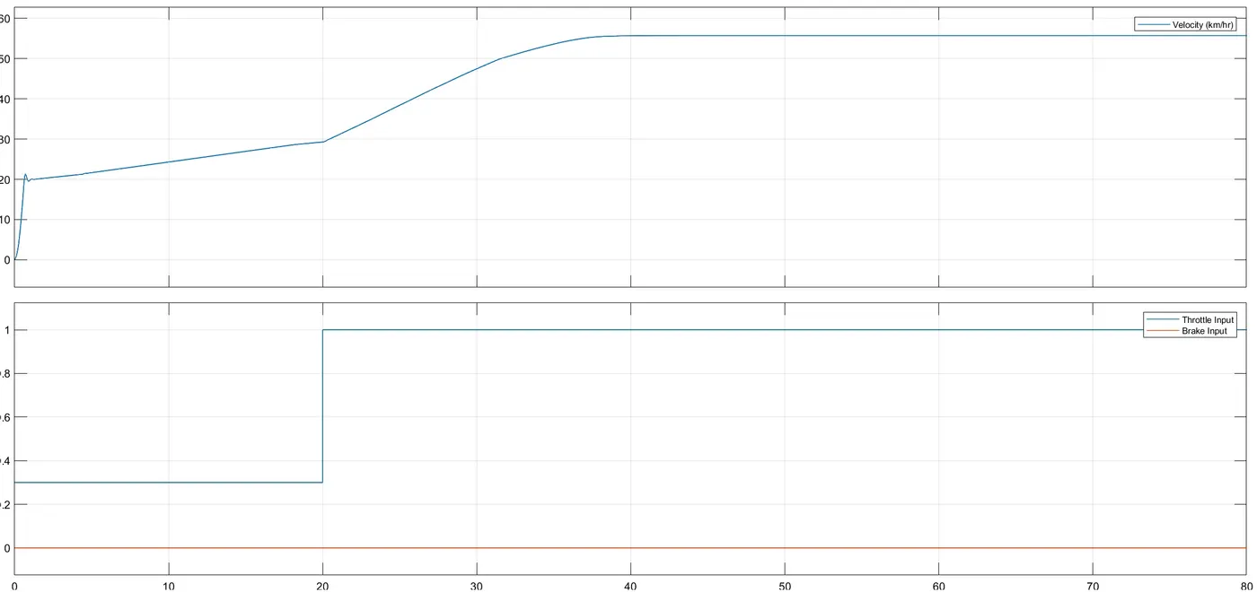
Vehicle speed output scope: We can observe that velocity is almost constant after 40 seconds and signal builders have constant and variable signal.
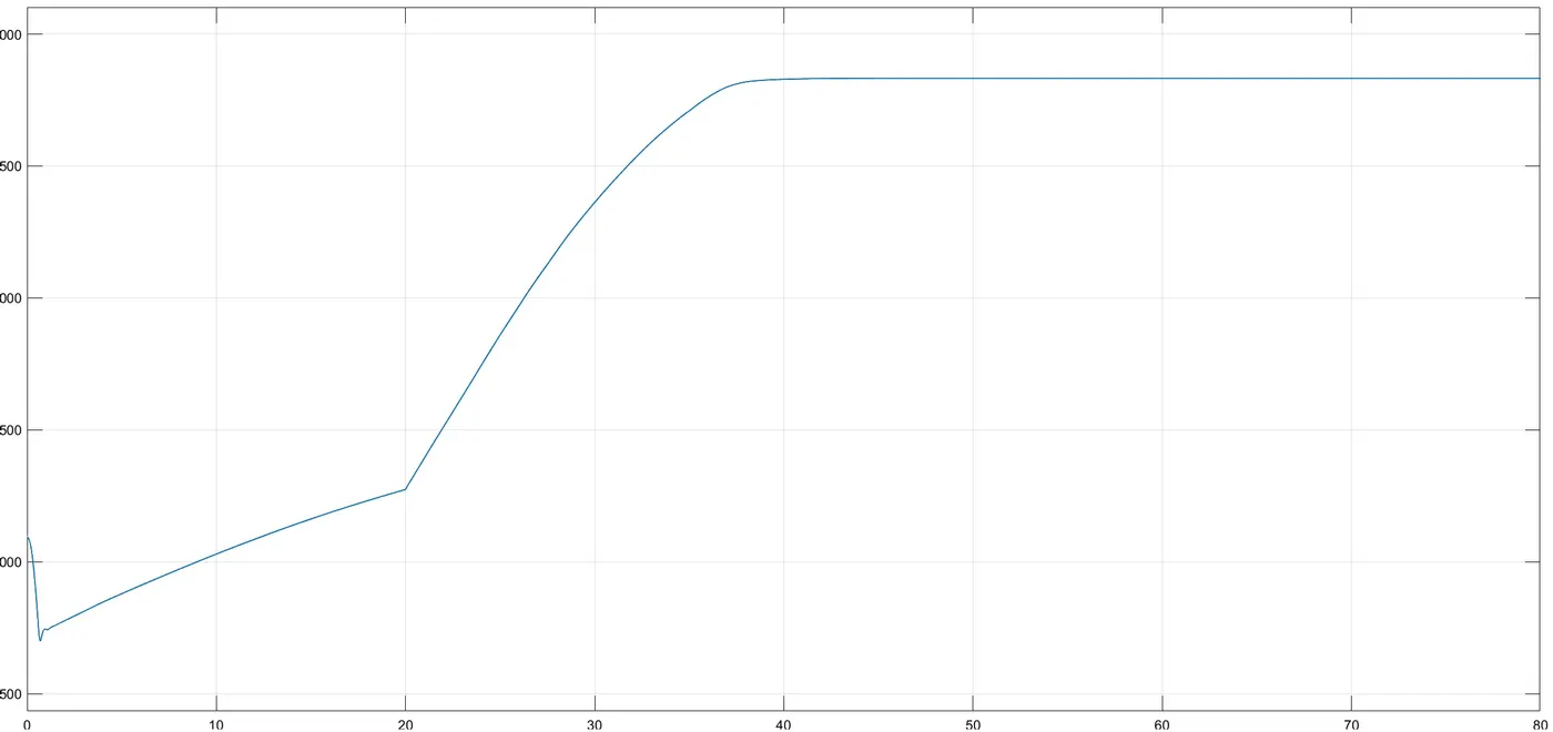
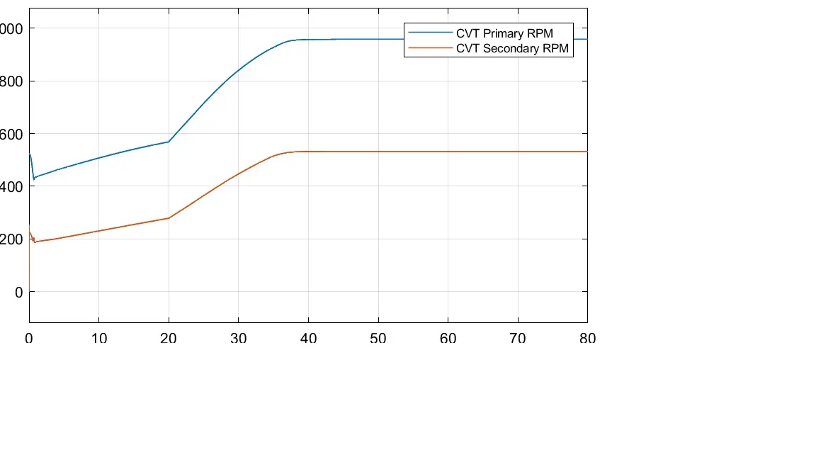
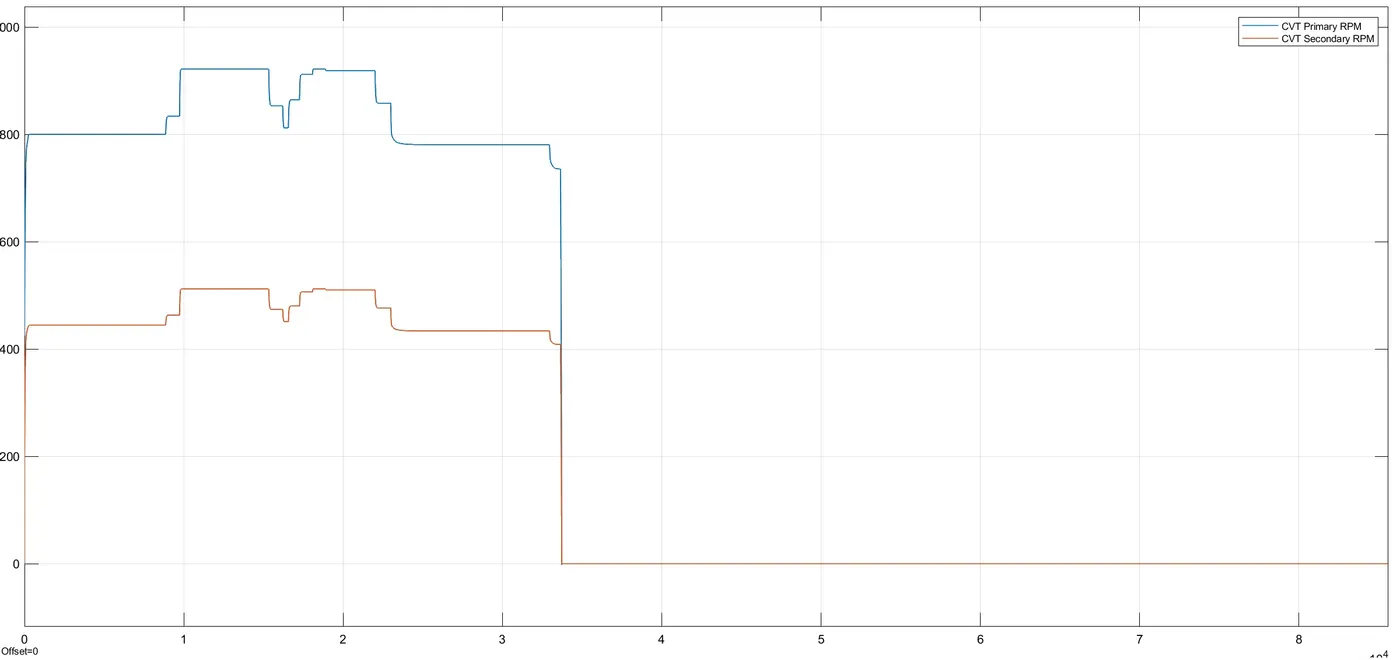
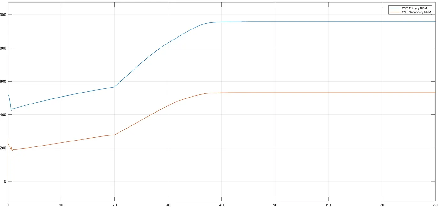
CVT shaft speed output: We can observe that after 40 seconds speed becomes almost constant upto 80 seconds.
Torque vs speed plot:
Model 1.2: BAJA ATV MODEL WITH DASHBOARD
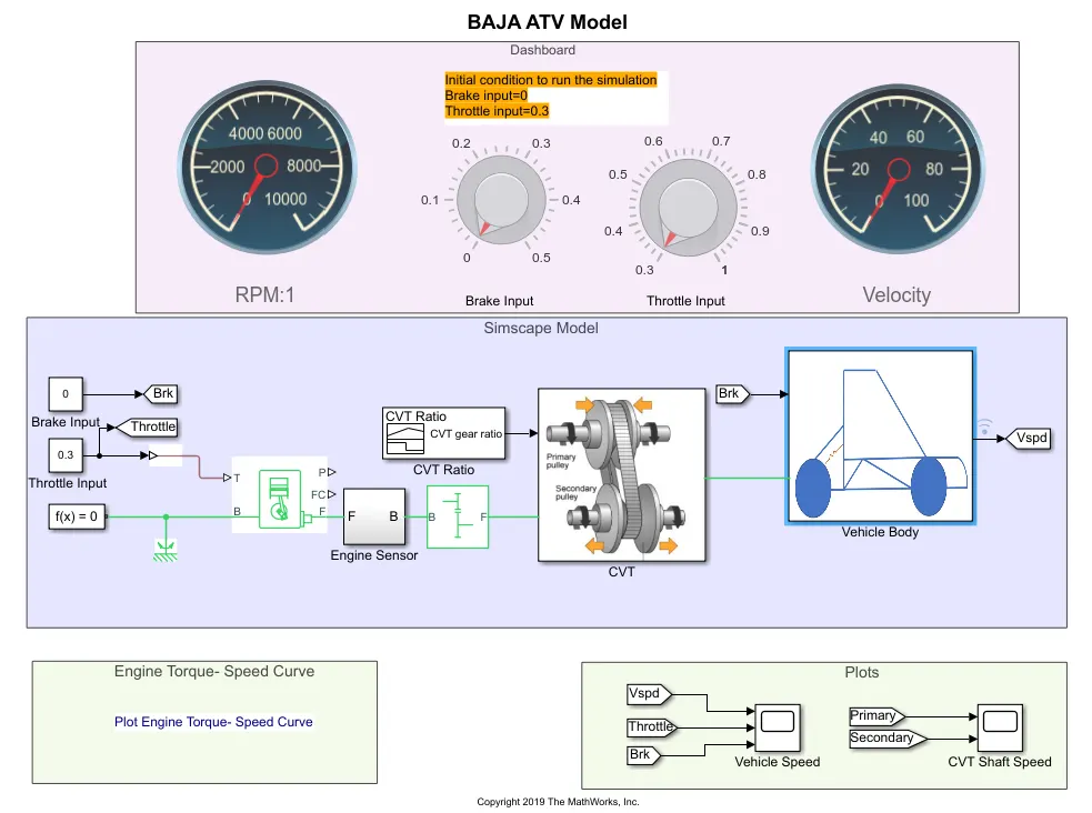
- In this model same blocks are used with CVT. The type of inputs are changed for solution.
- In the previous one, we gave signal builder as input, now, we give a constant block. Constant blocks are connected to the knobs.
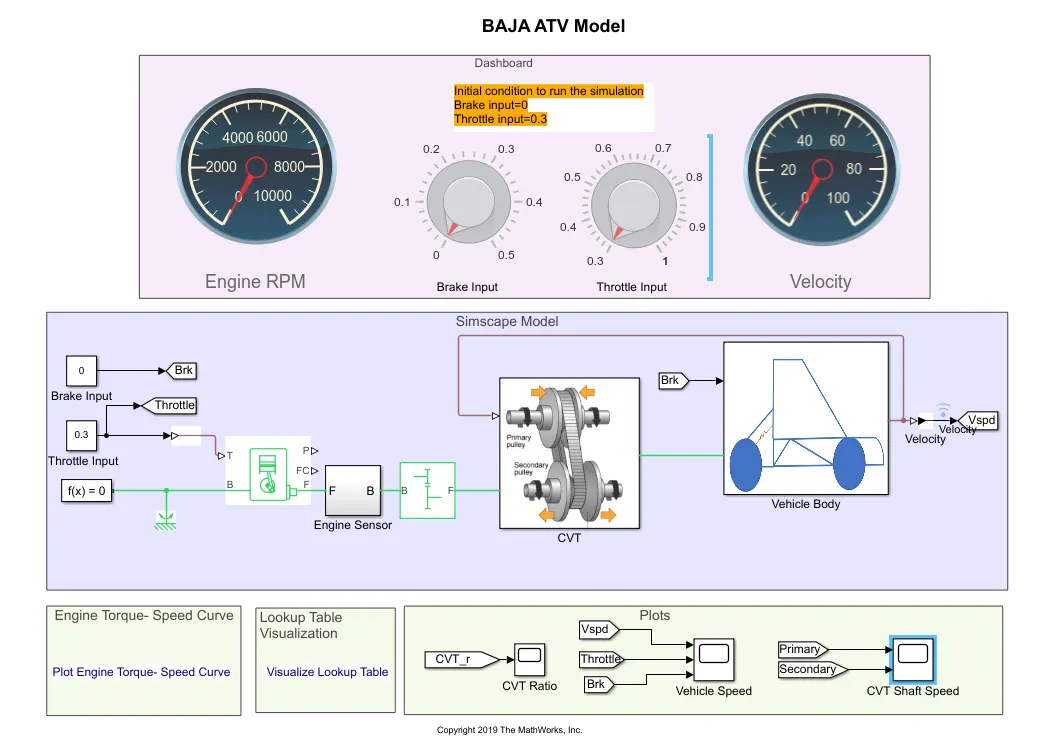
- Dash board is added to the model. It contains two knobs and two circular gauges. Knobs are used for changing the input values of throttle and brake.
- For brake input knob limits are 0 and 0.5 and for throttle input knob, limits are 0.3 and 1.
- Gauges are used for sensing RPM and velocity. These are changed while the simulation is done. Gauges are connected with the help of log signals.
- The output from vehicle body which is the velocity is connected to gauge and another one is connected to engine sensor.
- Run the simulation for infinity sample time and change the values at knob while the simulation is done.
Model:
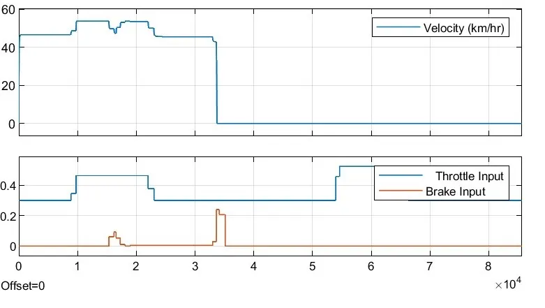
Scope for input and vehicle speed: We can observe that changes made through the knob for throttle and brake. Velocity is output for the vehicle body.
Scope of CVT shaft speed: CVT input and output are compared. The engine speed is reduced by CVT ratio.
Model 2.1: BAJA ATV WITH LOOKUP TABLE
- In this model we change the input type for CVT subsystem.
- We are taking values from the workspace.
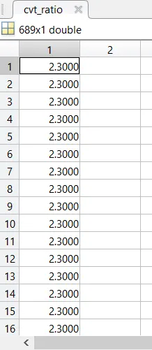
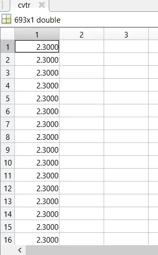
- Values are cvt_ratio and cvtr are in workspace.
Model: BAJA ATV MODEL WITHOUT DASHBOARD
Values:
Engine torque- Speed curve:
Scope of CVT shaft speed:
Scope of Vehicle speed:
Model 2.2: BAJA ATV WITH LOOKUP TABLE
Model inofrmation:
- This is the model where dashboard is not used and inputs are chnaged. The type of input for throttle and brake is changed.
- Step blcoks are used for graph, is built and given to the engine. Step time of 30 with initial value of 0.3 is used for throttle input step block.
- Step time of 35 and initial value is given as 0 for brake input step block.
- 2D-lookup table is used for CVT and linear methods are used.
Model:
CVT subsystem:
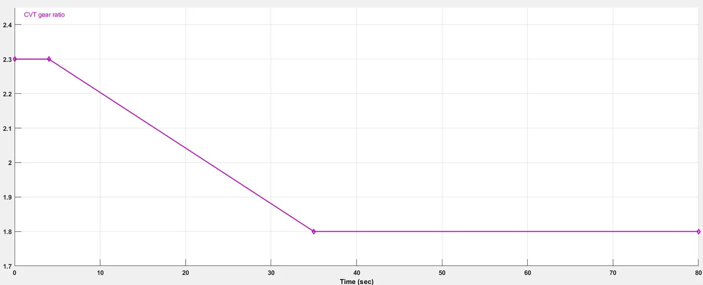
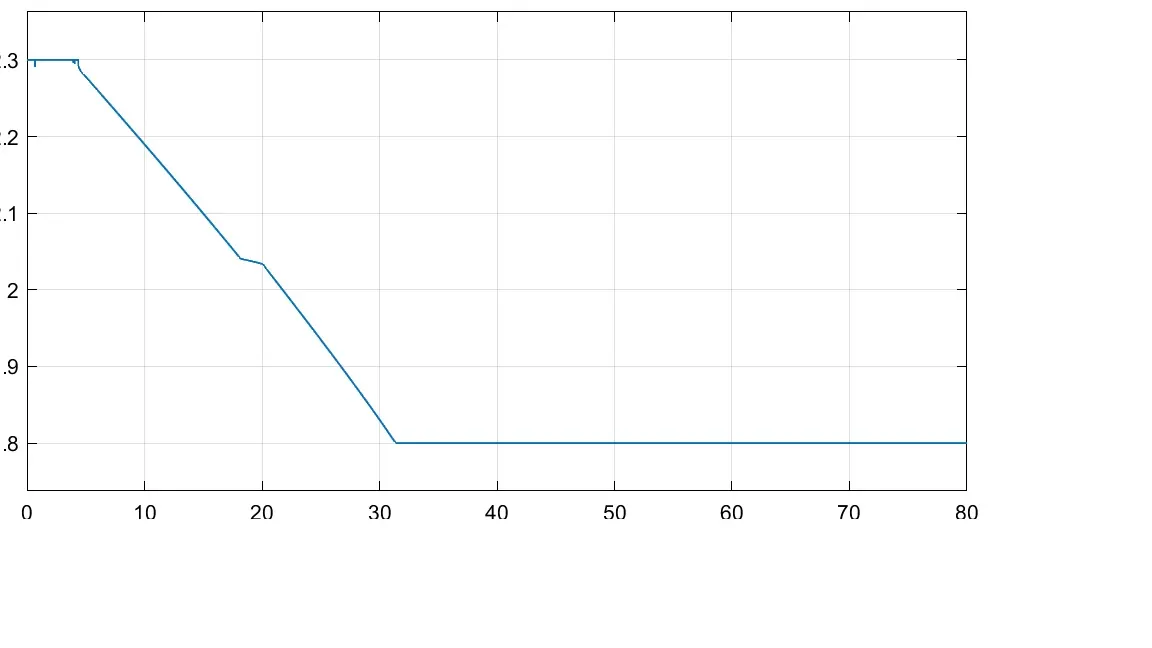
Lookup table: We can observe that CVT ratio is changed from 2.3 to 1.8. Constant velocity is achieved after some time.
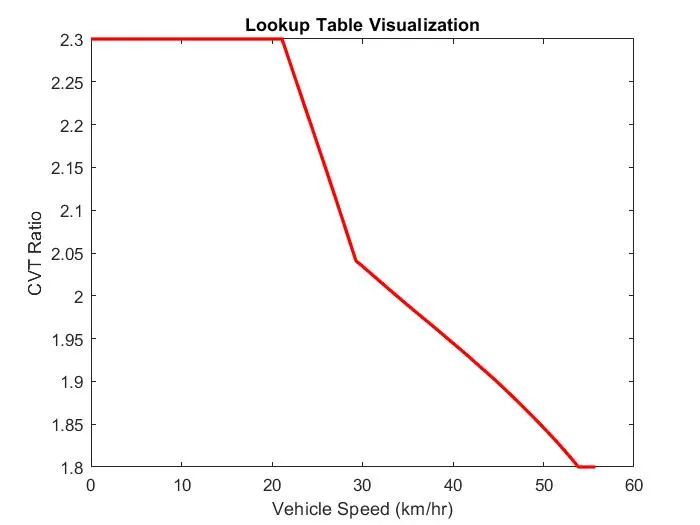
CVT ratio: CVT ratio is changed from 2.3 to 1.8 in the sample time of 80 seconds.
CVT shaft speed:
Vehicle speed:
Model 2.3: BAJA ATV MODEL WITH DASHBOARD
Model inoformation:
- Dashboard with lookup table is used ofr solving.
- In dashboard, throttle and brake inputs are controlledby the knobs.
Model:
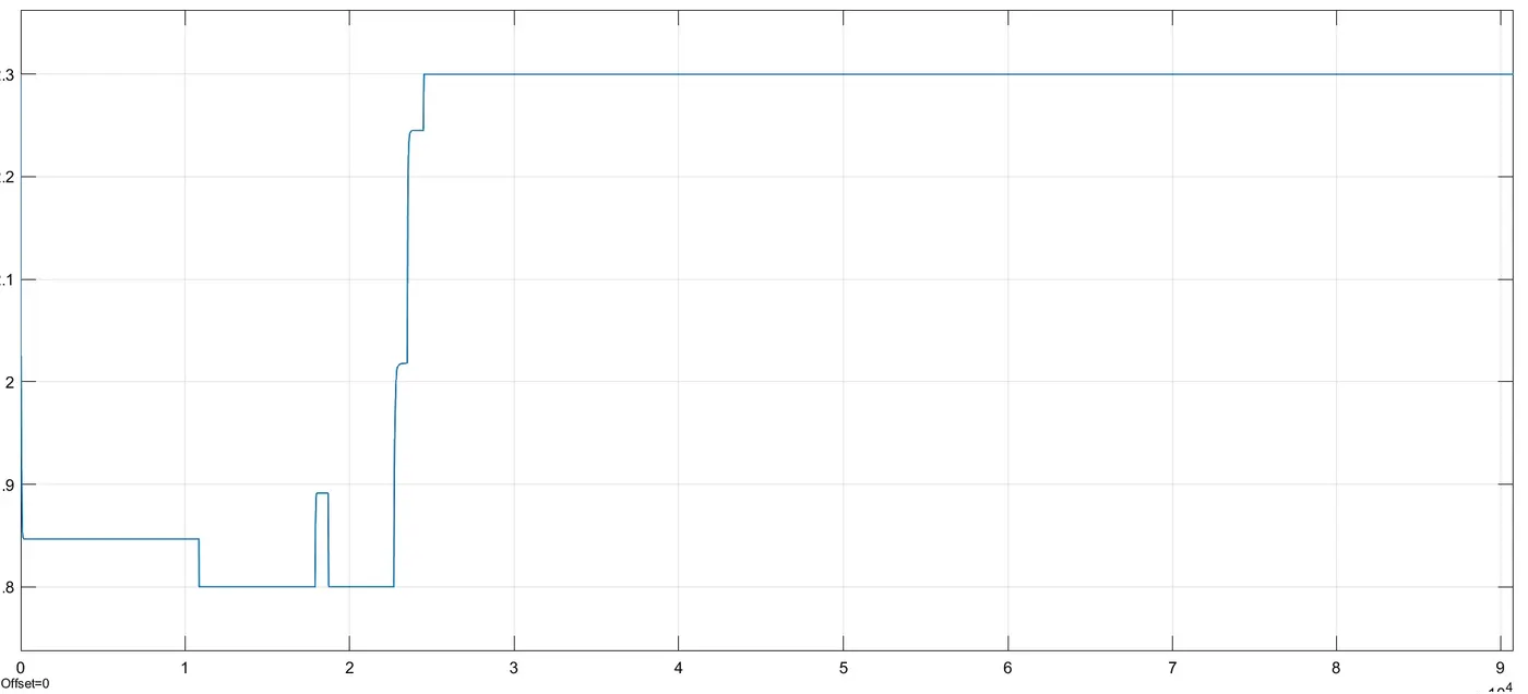
CVT Ratio: We can say that when CVT ratio is increased, the throttle is decreased and viceversa. As CVT ratio increses braking increses and as viceversa.
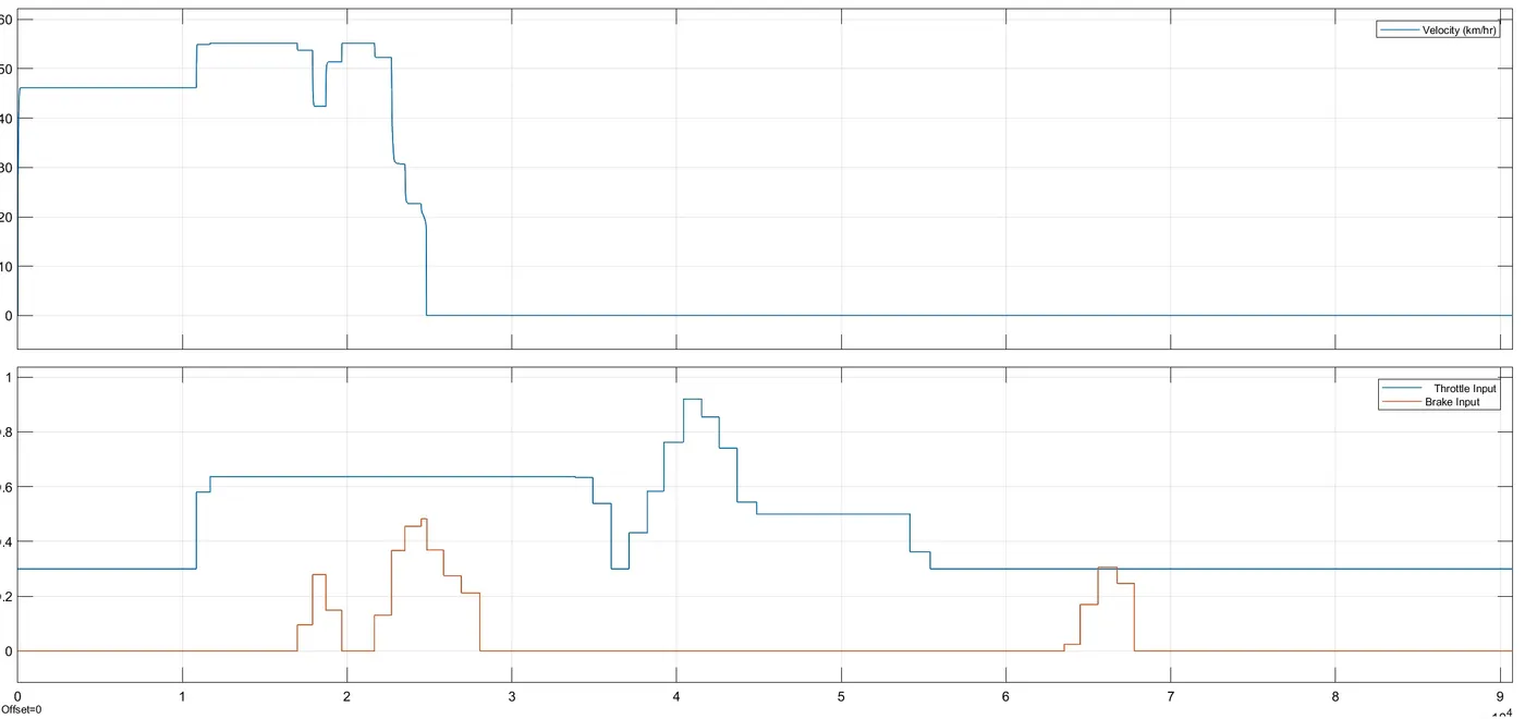
Vehicle speed: We can observe that velocity and inputs are compared. We can observe as brake is applied, speed is decreased.
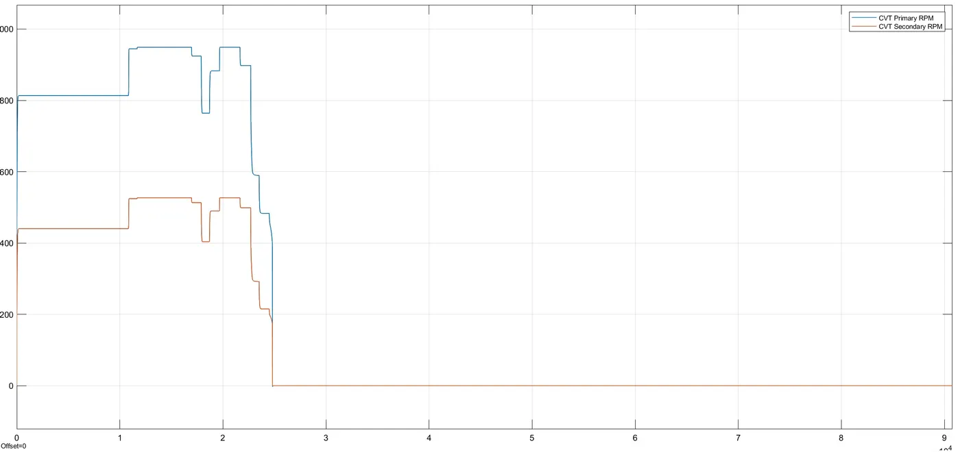
CVT shaft speed:
References:
https://en.wikipedia.org/wiki/Continuously_variable_transmission
https://auto.howstuffworks.com/cvt.htm
https://in.mathworks.com/support/search.html?q=inertia%20block&page=1
https://in.mathworks.com/help/
https://en.wikipedia.org/wiki/Baja_SAE
Conclusion:
Hence, BAJA ATV model is studied with Continuous Variable Transmission.