Project
AIM
To carry out a system-level simulation of an all-terrain vehicle and to explain the model properties & comments on the results.
THEORY
All Terrain Vehicles(ATV)
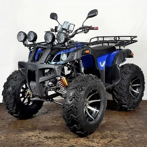
An all-terrain vehicle (ATV), also known as a light utility vehicle (LUV), a quad bike, or simply a quad, as defined by the American National Standard Institute (ANSI), is a vehicle that travels on low-pressure tires, with a seat that is straddled by the operator, along with handlebars for steering control. As the name implies, it is designed to handle a wider variety of terrain than most other vehicles. It is designed to travel on four low-pressure or non-pneumatic tires, having a seat designed to be straddled by the operator and handlebars for steering control. ATVs are subdivided into two types as designated by the manufacturer. Type I ATVs are intended by the manufacturer for use by a single operator and no passenger. Type II ATVs are intended by the manufacturer for use by an operator and a passenger, and are equipped with a designated seating position behind the operator.
Gear Transmission in Cars
All the drive-train components that help transmit the engine power to the wheels are a part of the ‘Transmission’ system. Of which the gearbox is an integral part. These components include the clutch, gearbox, couplings, propeller shaft, axle shafts, and differential. In general, ‘Transmission’ usually refers to the car’s gearbox. However, some car designs integrate the gearbox and differential assembly into a single unit called ‘Transmission’ or ‘Trans-Axle.’
In a car, a transmission, or a gearbox, acts as the medium that transmits power generated by the engine to the wheels via a mechanical system of gears and gear trains. A transmission allows a person to apply power to a vehicle in a controlled manner, without which, the car would not efficiently move. Lower gears in a gearbox provide the required torque to accelerate while higher gears help attain high speed by using the engine’s power more effectively.
Gear Box
A gearbox comprises various gears, synchronizing sleeves, and a gear-shifting mechanism fitted inside a metal housing. The metal housing, usually made of aluminum/iron casting, accommodates all the gears. The gearbox is a part of the ‘transmission’ system. The gears play an important role in transmitting the engine power to the wheels
A gearbox contains gears of different sizes. It is mainly because of the vehicle’s varying demands for the torque required at the wheels depending upon the road, terrain & load. E.g., if a vehicle is climbing a slope, it needs higher torque than cruising on a straight road.
Furthermore, the first gear is the biggest in a gearbox and provides maximum torque output while producing minimum speed. Hence, the drivers use it when climbing slopes. All the gears between 1st and last gear vary in size, in a decreasing ratio. Thus, it provides a varying combination of pulling ability and speed. So, you could drive the vehicle smoothly without any drop in its acceleration. The gearbox, basically, improves the vehicle’s driveability in all conditions.
car transmission is one of the most important components of a vehicle. It’s what moves the power from the engine to the wheels.
- Automatic Transmission (AT)
- Manual Transmission (MT)
- Automated Manual Transmission (AM)
- Continuously Variable Transmission (CVT)
Continuously Variable Transmission (CVT)
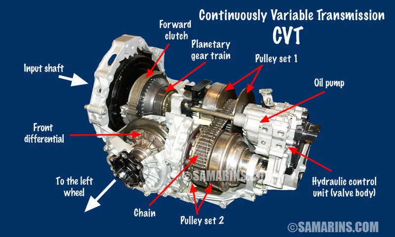
A CVT, or continuously variable transmission, seamlessly changes through an unending range of effective gear ratios while you drive, whereas other kinds of mechanical transmissions offer a fixed number of gear ratios and have hard shifts between each as explained by Certified Transmission Repair. CVT transmission systems are also known as single-speed, shiftless, and stepless transmissions. The shiftless nature of a CVT offers unparalleled flexibility that maintains constant angular velocity regardless of output speed. Additionally, a continuously variable transmission makes accelerating smooth and offers enhanced fuel economy.
This transmission has a continuously variable drive ratio (as opposed to conventionally stepped gear ratios) and uses belts, pulleys and sensors rather than gears to maintain a steady acceleration curve with no pauses for gear changes. Because of this, a CVT can keep the engine in its optimum power range, thereby increasing efficiency and gas mileage.
Working
Technically, a CVT is an automatic transmission because the driver isn't required to shift between the forward gears or operate a clutch pedal manually. But there are fundamental differences in both form and function between the two.
Unlike a traditional automatic (or manual transmission, for that matter), a CVT does not have a fixed number of preset gears. Instead, it uses an unlimited number of gear ratios to accommodate the driving style and conditions at any given moment. Because it allows seamless changes without any hard shift points, a CVT transmission is often referred to as "single-speed" or "shiftless."
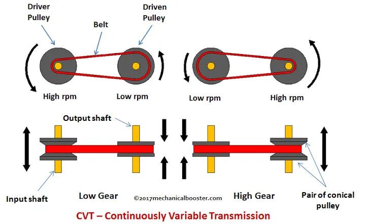
A CVT achieves this infinite gear ratio flexibility by using two opposing cone-shaped pulleys with a chain or belt that runs between them. This setup is very similar to the way a chain operates across the gears of a bicycle.
One cone is connected to the engine output shaft, while the other cone directs power to the driveshaft and drive wheels. Gear ratios change as the pulleys move closer and further apart, causing the chain or belt to move up and down the two cones' sides. This movement increases or decreases the diameter of the chain or belt, which alters the gear ratio based on the power needed. These real-time changes happen continually as the car is moving.
Advantages
- Increased fuel economy: CVTs are more efficient than standard automatic transmissions and are commonly utilized in hybrid powertrains and smaller cars to maximize the number of miles you can travel on every gallon of gas.
- Responsive acceleration: Due to its variable characteristics, a CVT can typically find the proper gear ratio much faster than an automatic transmission at virtually every speed ranging from off-the-line to highway passing.
- Smoother driving character: The absence of hard shift points means a CVT delivers more consistent performance across the engine's rev band. There are no abrupt downshifts or lags in acceleration as experienced with automatic and manual transmissions.
Disadvantages
- Lack of character: There is little to no shifting feel which results in a driving experience that can be bland and uninteresting.
- Noisiness: Many drivers find CVTs to be louder and whinier than traditional automatic transmissions. Under hard acceleration, such as when entering a freeway, they tend to drone. This trait contributes to a less enjoyable driving character.
- Lack of high-performance capability and durability: Although CVTs offer better than average acceleration in everyday driving situations, they are not ideal for high horsepower applications or sustaining high speeds. For that reason, CVTs are typically not utilized in sports cars.
- Higher repair costs: Not only do CVTs cost more to fix or replace, they generally do not last as long as traditional automatic transmissions.
BLOCKS USED
- Signal Builder: To create signal inputs of Throttle, Brake, cvt Ratio. The Signal Builderblock allows you to create interchangeable groups of piecewise linear signal sources and use them in a model.
- Goto: To pass the input to the corresponding From Goto block allow you to pass a signal from one block to another without actually connecting them.
- Simulink PS Converter: To convert Simulink signal to Physical signal.
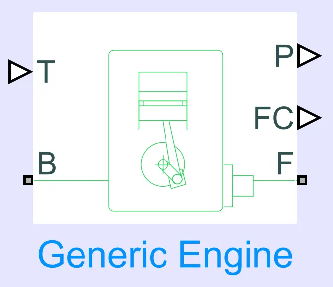
- Generic Engine: Represents a general IC engine. This block uses a programmed relationship between torque and speed that is modulated by the throttle signal.
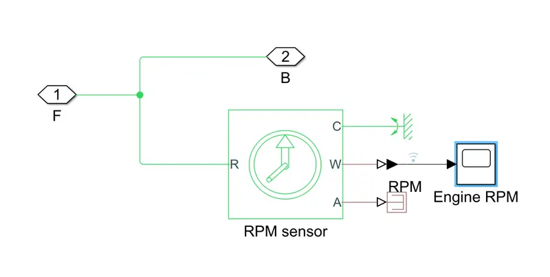
- Engine Sensor: Represents a sub system which consists of:
- Ideal Rotational Motion Sensor: To sense the angular velocity of the engine. It represents an ideal mechanical rotational motion sensor, that converts an across variable measured between two mechanical rotational nodes into a control signal proportional to angular velocity or angle. The sensor is ideal since it does not account for inertia, friction, delays, energy consumption, and so on.
- PS Simulink Converter: To convert physical signal to Simulink signal
- Scope: To plot the angular velocity (here Engine RPM).
- Mechanical Rotational Reference: Represents a reference point for all mechanical rotational ports
- PS Terminator: To terminate physical signal outputs. We can use a PS Terminatorblock for clarity, to indicate that the signal was not inadvertently left unconnected.
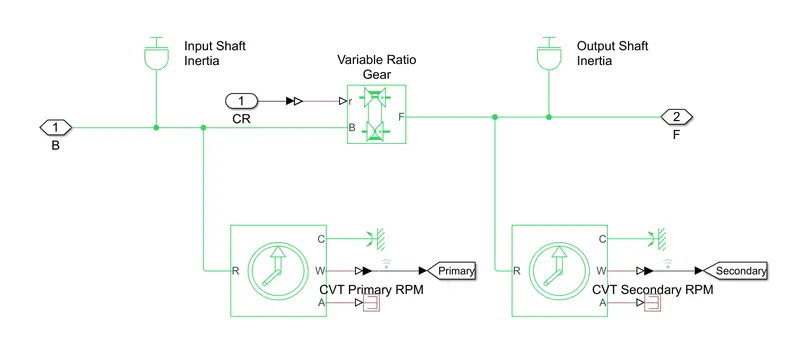
- CVT: Subsystem representing Continuous Variable Transmission and it consists of:
- Inertia Block: To represents an ideal mechanical translational inertia
- Variable Ratio Transmission: Represents a gearbox that dynamically transfers motion and torque between the two connected driveshaft axes, the base and the follower.
- Ideal Rotational Motion Sensor: To sense the angular velocities of primary and secondary shafts.
- PS Simulink Converter: To convert physical signal to Simulink signal
- Mechanical Rotational Reference: Represents a reference point for all mechanical rotational ports
- PS Terminator: To terminate physical signal outputs. We can use a PS Terminatorblock for clarity, to indicate that the signal was not inadvertently left unconnected.
- Goto: To pass the input to the corresponding Fromblocks
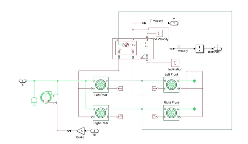
- Vehicle Body: Represents a subsystem of the body of the vehicle. It contains:
- Tire: It models a tire with longitudinal behaviour given by the Magic Formula, an empirical equation based on four fitting coefficients. The block can model tire dynamics under constant or variable pavement conditions The longitudinal direction of the tire is the same as its direction of motion as it rolls on pavement.
- Double Shoe Brake: Represents a frictional brake with two pivoted rigid shoes that press against a rotating drum to produce a braking action
- PS Terminator: To terminate physical signal outputs. We can use a PS Terminatorblock for clarity, to indicate that the signal was not inadvertently left unconnected.
- Inertia Block: To represents an ideal mechanical translational inertia
- Gain: To multiplies the input by a constant value. The input and the gain can each be a scalar, vector, or matrix.
- Vehicle Body block: It represents a two-axle vehicle body in longitudinal motion. The vehicle can have the same or a different number of wheels on each axle. For example, two wheels on the front axle and one wheel on the rear axle. The vehicle wheels are assumed identical in size. The block accounts for body mass, aerodynamic drag, road incline, and weight distribution between axles due to acceleration and road profile. Optionally include pitch and suspension dynamics. The vehicle does not move vertically relative to the ground. The block has an option to include an externally-defined mass and an externally-defined inertia.
- PS Constant: To generate a physical signal of a constant value. You specify the value and unit of the signal as the Constant
- Integrator: The Integratorblock outputs the value of the integral of its input signal with respect to time.
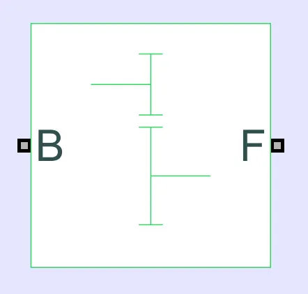
- Simple Gear: To represents a gearbox that constrains the connected driveline axes of the base gear and the follower gear to corotate with a fixed specified ratio.
- From: To accepts a signal from a corresponding Gotoblock, then passes it as output. The data type of the output is the same as that of the input from the Goto From block allow you to pass a signal from one block to another without actually connecting them.
- Scope: To displays the plotted graphs during the simulation.
- Solver Configuration: To specifies the solver parameter that the model needs before starting the simulation.
- Mechanical Rotational Reference: Represents a reference point for all mechanical rotational ports
- Knob: To tunes the value of the connected block parameter to during simulation. We can adjust the value of connected block during simulation
- Circular Gauge: To displays the value of the connected signal on a circular gauge. The Circular Gaugeblock displays the instantaneous value of the connected signal throughout simulation. We can modify the range and tick values on the Circular Gauge block to fit your data.
PART 1: CVT MODEL
MODEL
WORKING
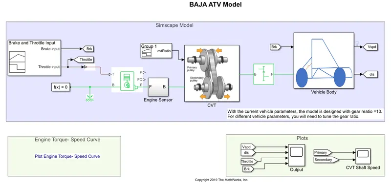
- At the initial condition the vehicle model will work according to the initial setup set by the developers.
- The inputs to the generic engine are given by using ‘speed vector’ and ‘torque vector’, created in the Matlab workspace.
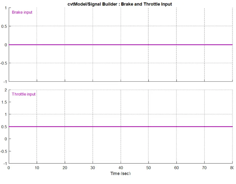
- The throttle and brake inputs are given by using ‘Signal Builder’.
- The Generic engine based on the given inputs of Torque, speed, throttle and brake will pass the signal to Engine Sensor block where Angular Velocity (here Engine RPM) and angular displacement is measured by using Ideal Rotational Motion Sensor (RPM Sensor). A Scope is connected to get the Engine RPM.
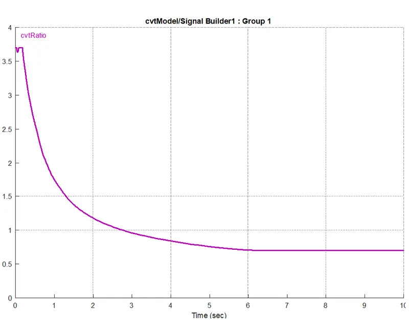
- This Signal from Engine Sensor is passed to one of the inputs of the CVT block. Other input is connected to a Signal Builder block which gives CVT Gear Ratio. Cvt Block consist of input shaft inertia (Primary Pulley), output shaft inertia (secondary Pulley) which is connected to two Rotational Motion sensor to get the angular velocities of input and output pulleys respectively and can be seen by connecting scope. The signal in the input shaft is given to Variable Ratio Gear block where gear ratio changes according to the given cvt ratio during the simulation and is connected to output shaft inertia
- The signal from output shaft inertia is connected to vehicle body through Simple Gear. In the vehicle body block there are two inputs, one is from the cvt block which is connected to the Rear Wheels and then to the front wheels. The other input is the brake input which is coming from the signal builder of brake input and is connected to Double Shoe Brake. The Double Shoe Brakes are regular drum brakes used in most of the vehicles and is to apply brake to rear wheels which will reflects on tires and body. All these are then connected to Vehicle Body
- The Vehicle Body consist of body mass, aerodynamic drag, road incline, weight distribution between axles due to acceleration and road profile, pitch and suspension dynamics. All these values are made as per Baja design specifications. The velocity and distance travelled can be found from the scope.
Brake & Throttle Input
CVT Ratio Input
Engine Parameter Input
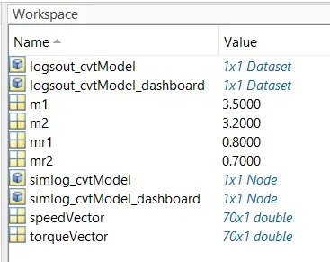
These are the input parameters to the generic engine given from Matlab Workspace
RESULT
Engine Torque VS Speed Curve
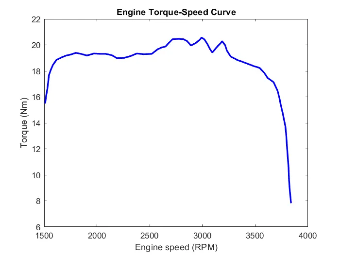
Engine parameters given from Matlab Workspace is same for both the models. So Engine Torque-Speed curve will be same for both the models
Engine RPM
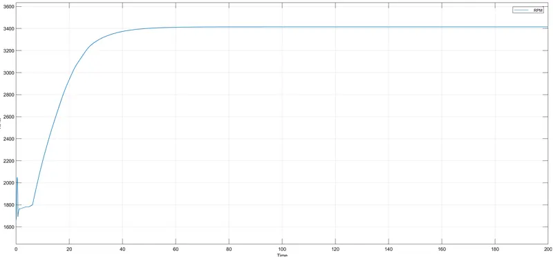
During the simulation, at starting the engine rpm is low. As the throttle value changes rpm is slowly increasing and after certain point when throttle value reaches maximum, the engine is running at maximum rpm. After that till the end of the simulation there is no change in throttle value hence the engine RPM, i.e vehicle is moving in constant speed till the simulation is completed.
Velocity
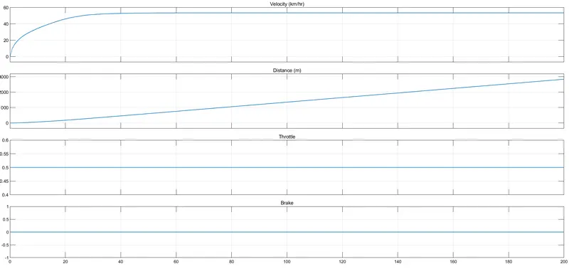
From the plot it is clear that brake and throttle values are constant i.e Brake input is 0 and Throttle input is 0.5. At the initial condition the velocity is minimum because at starting we need more torque. Then velocity is gradually increasing up to a certain point and become constant till end of simulation. At this time torque will be minimum.
We know that Distance = Velocity x Time
Since velocity is increasing with respect to time in Velocity-Time plot, distance travelled is also increasing.
CVT Shaft Speed
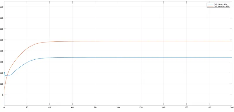
This depends upon the CVT gear ratio which is given as input. At initial state the speed of primary shaft is more than that of secondary (output shaft) i.e output shaft is rotating slowly, means torque is high and the velocity is low. Then speed of both shafts are increasing gradually and becoming constant. At certain point, speed of secondary shaft is more than that of primary implies torque is less and velocity is high and the vehicle is moving at high velocity in rest of the simulation.
File Link
https://drive.google.com/file/d/1v6_nSaBGK8iySq5bz-lIzA0yeqxaKKVp/view?usp=sharing
PART 2: CVT MODEL WITH DASHBOARD
WORKING
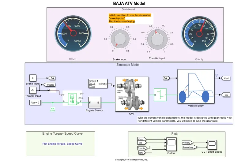
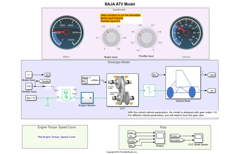
The Working is similar to the previous model. The difference is in the previous model Brake input and Throttle input was given by Signal Builder and was constant through out the simulation. But here Brake input and Throttle input is given with the help of Knobs which can be adjusted during the simulation and can be seen from the Gauges connected to the respective knobs.
2.1 Brake Input Constant (0) & Throttle Input Varying
MODEL
Here in this model we are varying throttle input by keeping brake input zero
RESULTS
Engine RPM
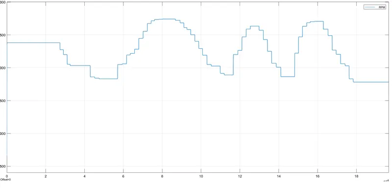
This shows the variation in Engine rpm with respect to change in throttle input. When value of throttle input increases, rpm also increases. Maximum the value of throttle input, the engine will run in high rpm.
Velocity
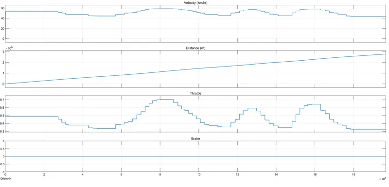
From the plot it is clear that throttle values are changing with respect to time and brake input value is zero i.e we are not applying any brake . At the initial condition the velocity is minimum because at starting we need more torque. Then velocity is gradually increasing up to a certain point. When we are adjusting the throttle input by adjusting the knob, variations in velocity can be observed. When value of throttle input increases, velocity also increases. Maximum the value of throttle input, the vehicle will run in high velocity and low torque.
CVT Shaft Speed
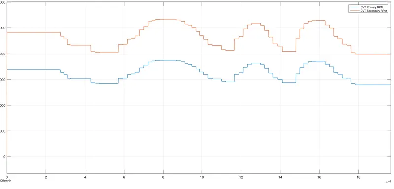
At initial state the speed of primary shaft is more than that of secondary (output shaft) i.e output shaft is rotating slowly, means torque is high and the velocity is low because at starting we need more torque. Then speed of both shafts are increasing gradually. At certain point, speed of secondary shaft is becoming more than that of primary shaft due to the cvt gear ratio, implies torque is less and velocity is high and the vehicle is moving at high velocity. As we are varying the throttle input, rpm of both shafts are changing accordingly but gear ratio remains same. When value of throttle input increases, rpm also increases.
2.2 Brake Input Varying & Throttle Input Constant (0.5)
MODEL
Here in this model we are varying brake input by keeping throttle input constant (0.5)
RESULTS
Engine RPM
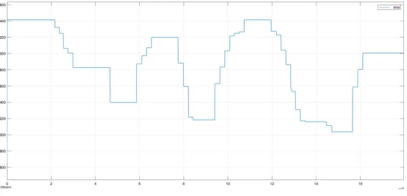
This shows the variation in Engine rpm with respect to change in brake input. When value of brake input increases, rpm decreases. Minimum the value of brake input, the engine will run in high rpm.
Velocity
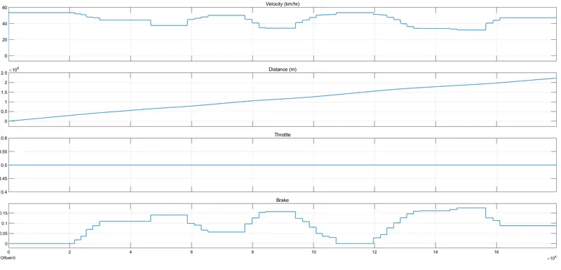
From the plot it is clear that brake input values are changing with respect to time and throttle input value is 0.5. At the initial condition the velocity is minimum because at starting we need more torque. Then velocity is gradually increasing up to a certain point. When we are adjusting the brake input by adjusting the knob, variations in velocity can be observed. When value of brake input increases, velocity decreases. Maximum the value of brake input, the vehicle will run in low velocity and high torque.
CVT Shaft Speed
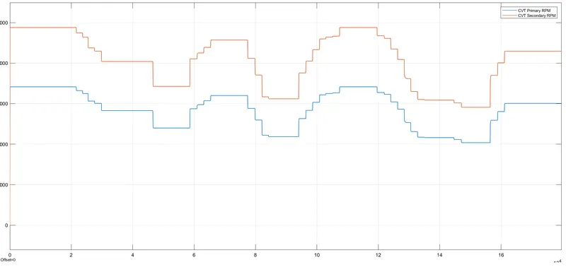
At initial state the speed of primary shaft is more than that of secondary (output shaft) i.e output shaft is rotating slowly, means torque is high and the velocity is low because at starting we need more torque. Then speed of both shafts are increasing gradually. At certain point, speed of secondary shaft is becoming more than that of primary shaft due to the cvt gear ratio, implies torque is less and velocity is high and the vehicle is moving at high velocity. As we are varying the brake input, rpm of both shafts are changing accordingly but gear ratio remains same. When value of brake input increases, rpm decreases.
File Link
https://drive.google.com/file/d/15cx4nuaxMkoEzqplqG3MTgG-I63t5JdV/view?usp=sharing
CONCLUSION
System-level simulation of an all-terrain vehicle has been carried out successfully and explained the model properties & results.
REFERENCE
https://www.jdpower.com/cars/shopping-guides/what-is-a-cvt-or-continuously-variable-transmission
https://www.caranddriver.com/research/a30822055/what-is-a-cvt-transmission/