Project
AIM: To carryout a system level simulation of an all terrain vehicle and prepare a technical report
Principle:The term ATV stands for All Terrain Vehicle. It is also known as a quad or quadricycle type vehicle. An All-Terrain motor vehicle could have three, four, or even six wheels. Unlike a motorcycle, generally, ATVs have more than two wheels. This vehicle runs on low-pressure tires. However, it has handlebars instead of a wheel for controlling the steering.
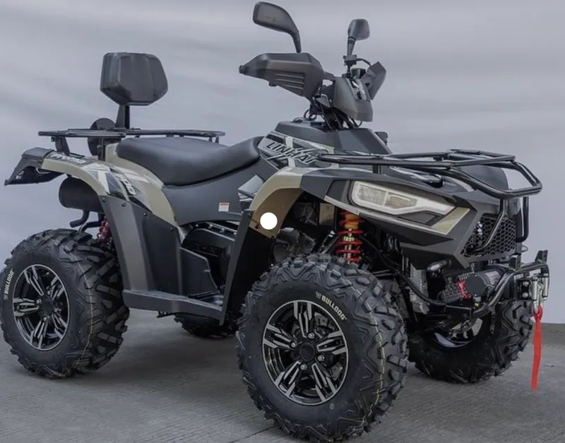
Baja SAE is an Collegiate Design series competition run by the Society of Automotive Engineers International (SAE International). Teams of students from universities all over the world design and build small off road cars. The cars all have engines of the same specifications. As of 2018 the engine has been an unmodified Briggs & Stratton Model 19 Vanguard engine single-cylinder with a displacement of 305cc and power output of approximately 10 bhp (7.5 kW).
The goal in Baja SAE racing is to design, build and race off-road vehicles that can withstand the harshest elements of rough terrain. The vehicles used in Baja SAE racing are often similar in appearance to dune buggies. Before 2007, the events were called "Mini Baja."
Each year as many as 141 Baja cars are entered in the Baja SAE events across the US and around the world. International events are endorsed by SAE International and are held in Brazil, Korea, South Africa and México.
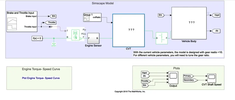
Model of a CVT transmission without Dashboard
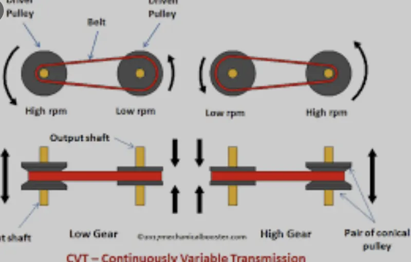
Continuously variable transmission
A CVT, or continuously variable transmission, seamlessly changes through an unending range of effective gear ratios while you drive, whereas other kinds of mechanical transmissions offer a fixed number of gear ratios and have hard shifts between each as explained by Certified Transmission Repair. CVT transmission systems are also known as single-speed, shiftless, and stepless transmissions.
The shiftless nature of a CVT offers unparalleled flexibility that maintains constant angular velocity regardless of output speed. Additionally, a continuously variable transmission makes accelerating smooth and offers enhanced fuel economy.
While a traditional transmission uses a wide variety of intricate parts to shift between a range of preset gears, most CVT systems work through a pulley system. In short, this system consists of cones at each pulley connected via a chain belt. The cones can move to increase or decrease the belt diameter to change gear ratios, allow for quick shifting into the needed ratio for increased power, and boost fuel economy.
One pulley in the CVT is connected to the engine and the other directs power to the wheels. The width of these pulleys changes based on the needed power; as one gets larger, the other gets smaller. This allows a CVT to deliver strong and seamless acceleration.
There is a second, less common, type of CVT that uses a series of discs and rollers, but it operates on similar principles.
Though there are no gears in a CVT, some simulate a more traditional changing of gears. In these transmissions, the belt-and-pulley system is designed to move to preset points by using a traditional shift lever or paddle shifters on the steering wheel.
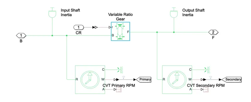
CVT blocks
Ideal Rotational Sensor is used to measure the RPM of the primary Pulley and Secondary Pulley
Blocks used in the models
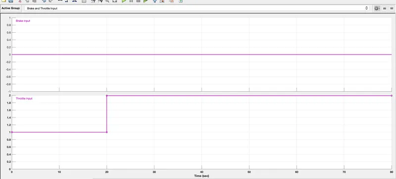
Signal Builder:The Signal Builder allows you to create interchangeable groups of piecewise linear signal sources and use them in a model. See Working with Signal Groups in Using Simulink for more information. Data Type Support. A Signal Builder block outputs a scalar or array of real signals of type double .By varying the Signals we can obtain the results acquired.The Brake and Throttle input can be varied using Signal Builder
Solver Configuration:The Solver Configuration block specifies the solver parameters that your model needs before you can begin simulation
Generic Engine:The Generic Engine block represents a general internal combustion engine. This block is a suitable generic engine for spark-ignition and diesel. Speed-power and speed-torque parameterizations are provided. A throttle physical signal input specifies the normalized engine torque. Optional dynamic parameters include crankshaft inertia and response time lag. A physical signal port outputs the engine fuel consumption rate based on the fuel consumption model that you choose. Optional speed and redline controllers prevent engine stall and enable cruise control.It can be used to vary the speed and torque vector
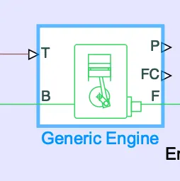
Engine Sensor: RPM Sensor Block is used to measure the Rpm of the engine under various stimulations
Simple gear :The Simple Gear block represents a gearbox that constrains the connected driveline axes of the base gear, B, and the follower gear, F, to corotate with a fixed ratio that you specify. You choose whether the follower axis rotates in the same or opposite direction as the base axis. If they rotate in the same direction, the angular velocity of the follower, ωF, and the angular velocity of the base, ωB, have the same sign. If they rotate in opposite directions, ωF and ωB have opposite signs.By varying the gear ratio we can find how its affect the velocity and find the optimal gear ratio
Variable Ratio Gear:The gear ratio between the follower (F) and the base (B) is steadily increased from 1:1 to 2:1. The ratio of the follower to base angular speed decreases with gear ratio, and conversely the ratio of the follower to base torque increases with gear ratio.
Double Shoe Break:The Double-Shoe Brake block represents a frictional brake with two pivoted rigid shoes that press against a rotating drum to produce a braking action. The rigid shoes sit inside or outside the rotating drum in a diametrically opposed configuration. A positive actuating force causes the rigid shoes to press against the rotating drum. Viscous and contact friction between the drum and the rigid shoe surfaces cause the rotating drum to decelerate.
Vehicle Body:The Vehicle Body block represents a two-axle vehicle body in longitudinal motion. The vehicle can have the same or a different number of wheels on each axle. For example, two wheels on the front axle and one wheel on the rear axle. The vehicle wheels are assumed identical in size. The vehicle can also have a center of gravity (CG) that is at or below the plane of travel.We can also vary the mass of the body to observe its effect on the velocity and dietance travelled. We can also vary the drag to determine the effects having over the Body
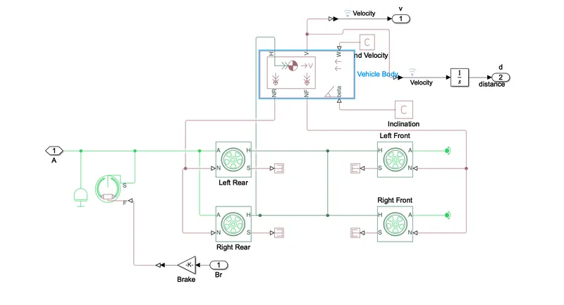
Tyre blocks are used as the behavior of the tyre also affects the Vehicle Body.By varying the tyre characteristics we can also vary the velocity of the Vehicle and Distance Travelled.
Ideal Rotational Motion:The Ideal Rotational Motion Sensor block represents an ideal mechanical rotational motion sensor, that is, a device that converts an across variable measured between two mechanical rotational nodes into a control signal proportional to angular velocity or angle.
Observations
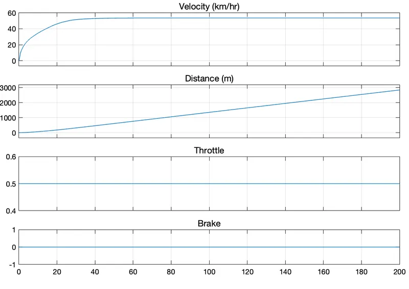
The plots shown below determine how velocity and distance travelled varies by chaning the Throttle and Brake
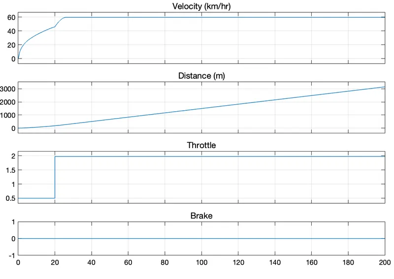
From figure(1) we can observe that by keeping the throttle constant and brake at Zero . The velocity increases gradually and reaches its maximum limit and becomes constant. The distance also increases over a period of time
From figure(2) by changing the Trottle and keepin the Brake Zero .The velocity gardually increases at first and then it increases sharply and eventaully reaches its maximum limit and becomes constant.From the velocity and Throttle graph we can observe that velocity increases sharply when the Throttle is increased and when the throttel becomes linear the velocity also becomes constant
From figure(3) By changing the Throttle and Brake. The velocity shraply increases and drops to zero as the brake is applied and distance also decreases
From this we can Determine how velocity and distance is affected by varying the input
Figure(1)
Figure(2)
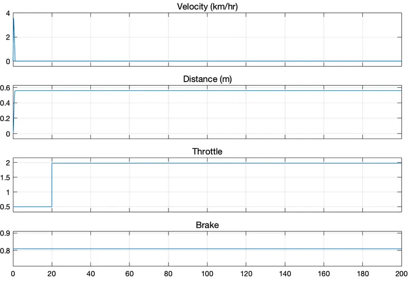
Figure(3)
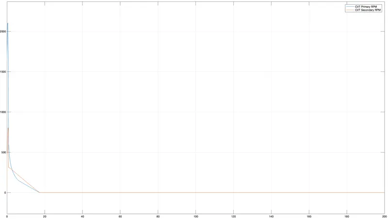
RPM of the primary and secondary pulley
The above Figure shows the Rpms of the Secondary pulley and Primary pullleys of the CVT.One pulley in the CVT is connected to the engine and the other directs power to the wheels. The width of these pulleys changes based on the needed power; as one gets larger, the other gets smaller.We can Observe that Rpm of primary pulley is higher when compared to the secondary Pulley By changing the gear ratio we can how the Rpms of the Pulley gets affected
Model with Dashboard
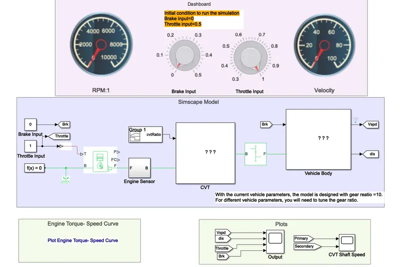
The difference btw this Model and Model shown earlier is the instead of using a signal builder a Rotary gauge is used for the Brake and Velocity input . The advantage is that we can vary the throttle and Brake as the simulation is running.The Velocity and rpm gauge is used to get output simultaneously as we vary the Throttle and Brake input