Project
AIM: To prepare a technical report on baja atv simulations.
Objective: 1.carry out a system level simulation on all-terrain vehicle.
2.prepare a technical report explaining model properties of Baja ATV.
ALL TERRAIN VEHICLE:
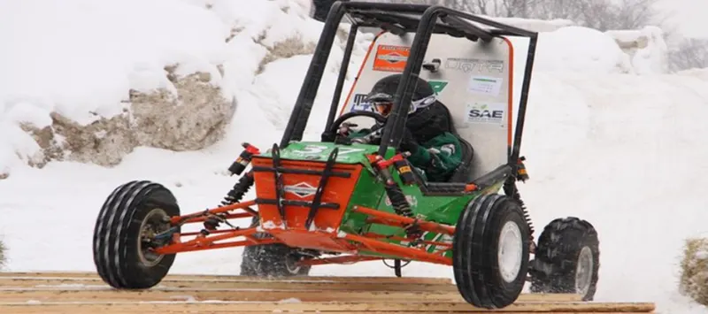
An all-terrain vehicle (ATV), also known as a light utility vehicle (LUV), a quad bike, or simply a quad, it is a vehicle that travels on low-pressure tires, with a seat that is straddled by the operator, along with handlebars for steering control. it is designed to handle a wider variety of terrain than most other vehicles.
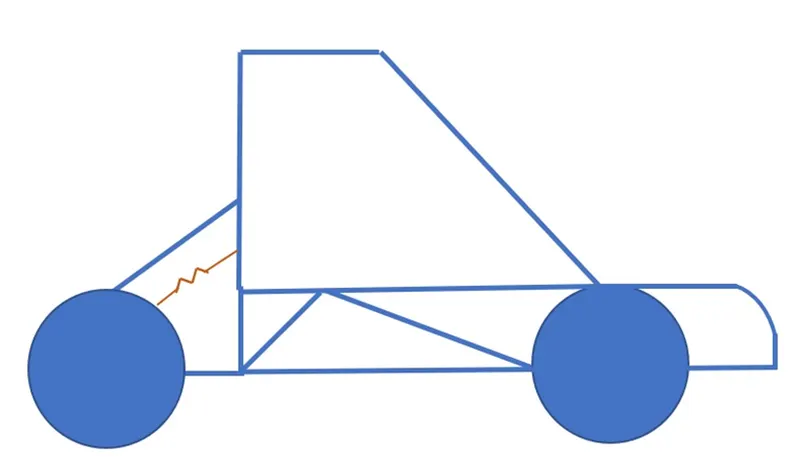
Study 1:
BAJA ATV model with Continuously Variable Transmission (CVT).
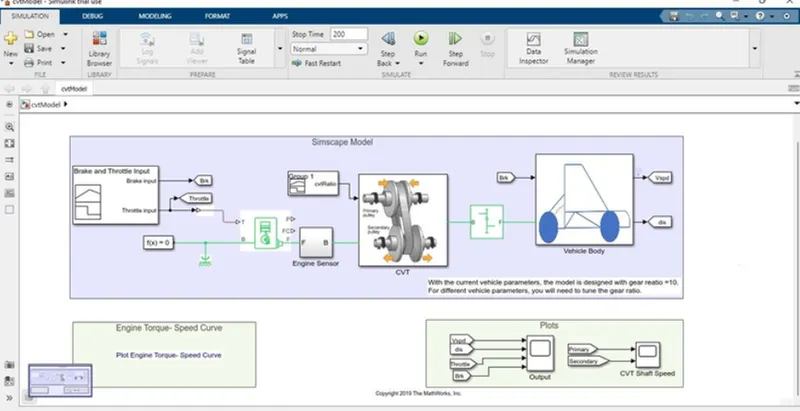
Major components used are:
- CVT(Continuously Variable Transmission):
- A continuously variable transmission (CVT) is automatic transmission that can change seamlessly through a continuous range of gear ratios. These contrasts
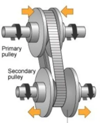
with other transmissions that provide a limited number of gear ratios in fixed steps. The flexibility of a CVT with suitable control may allow the engine to operate at a constant RPM while the vehicle moves at varying speeds.
B)CVT_BLOCK:
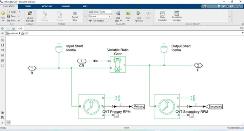
This block contains the primary and secondary cvt that reads the rpm data and delivers the output of the cvt in terms of speed.
2) Variable transmission ratio:
Represents a variable ratio gearbox such as implemented by mechanical belt CVT, electric, or hydraulic transmissions. The physical signal input r defines the ratio of input to output angular shaft velocities.
Connections B (base) and F (follower) are mechanical rotational conserving ports. Specify the relation between base and follower rotation directions with the Output shaft rotates parameter.
3) Ideal rotational Motion sensor:
This block measures angular velocity or angle in a mechanical rotational network. The sensor is ideal since it does not account for inertia, friction, delays, energy consumption, and so on.
The physical signal ports W and A report the angular velocity and angle, respectively, of port R relative to port C. The measured angular velocity is positive when the angular velocity at port R is greater than the angular velocity at port C.
4) Inertia:
The block represents an ideal mechanical rotational inertia.
The block has one or two mechanical rotational conserving ports. The difference is purely graphical, as the ports are rigidly linked. The block positive direction is from its port to the reference point. This means that the inertia torque is positive if the inertia is accelerated in the positive direction.
5) Generic engine:
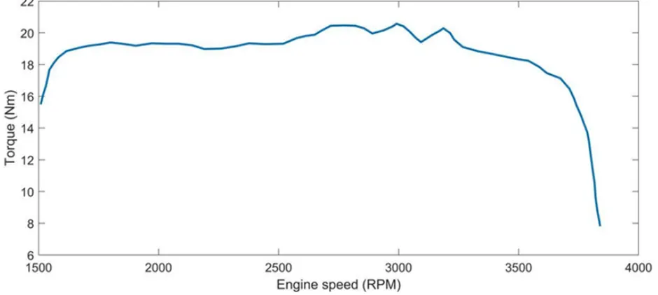
Represents a system-level model of spark-ignition and diesel engines suitable for use at initial stages of modelling when only the basic parameters are available. Optional idle speed and red line controllers are included.
The throttle input signal T lies between zero and one and specifies the torque demanded from the engine as a fraction of the maximum possible torque. If the engine speed falls below the Stall speed, the engine torque is blended to zero. If the engine speed exceeds the Maximum speed, the simulation stops and issues an error message. Connections F and B are mechanical rotational conserving ports associated with the engine crankshaft and engine block, respectively. Connections P and FC are physical signal output ports through which engine power and fuel consumption rate are reported.
6) INPUT SIGNAL:
7) GEAR RATIO INPUT:
8) TORQUE VS ENGINE:
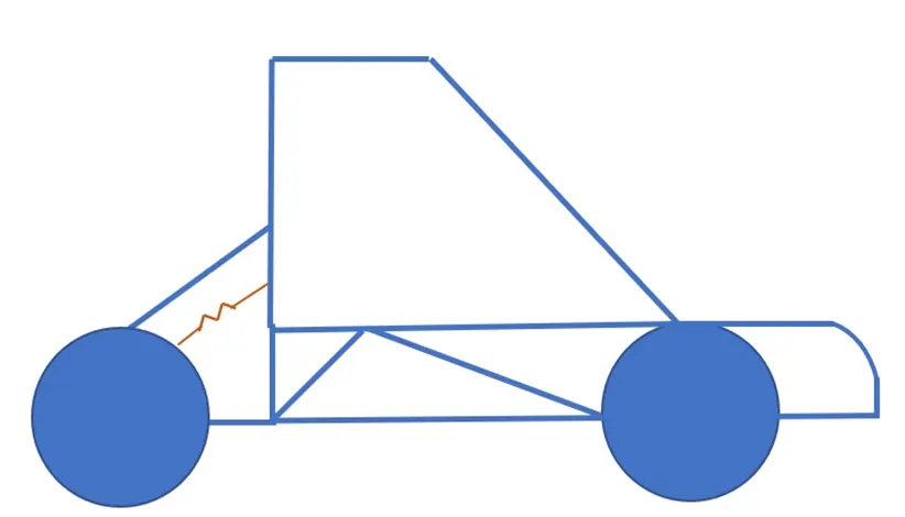
9) VEHICLE BODY:
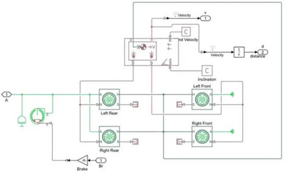
OUTPUT CASE 1:
MAX VELOCITY AND DISTANCE:
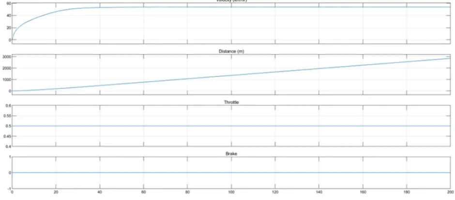
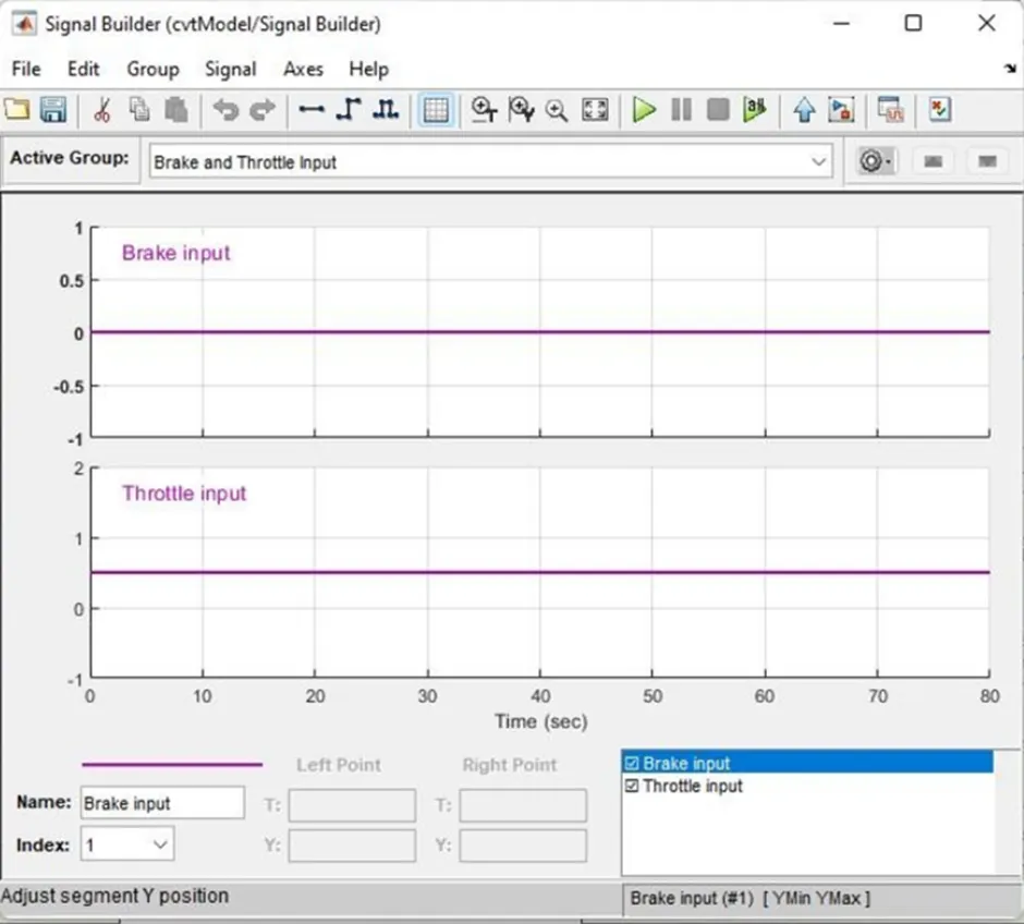
It’s clear that the total acceleration time taken was approx. to 32 secs to top speed of 52 km/hr the throttle is given up to 0.5 out of 1 50 percentiles. With no braking. The vehicle speed to max at 30 secs after approx.
CVT SHAFT SPEED PRIMARY AND SECONDARY:
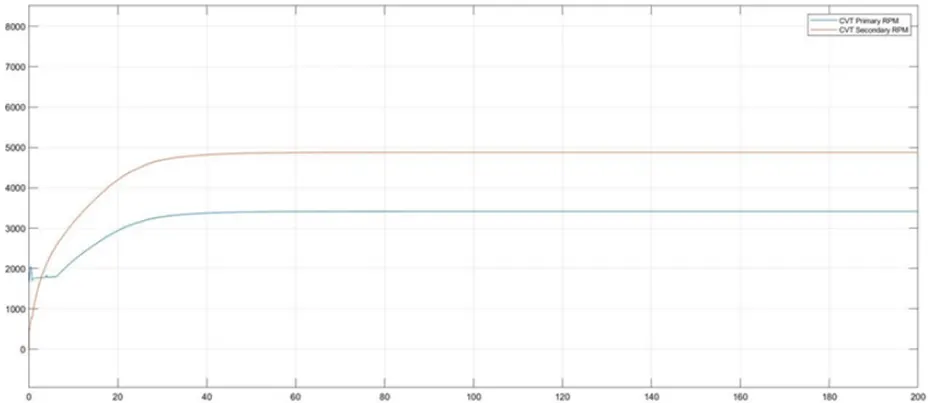
The angular speed of the shafts can be derived from the graph as the value differs with the different gear ratios. Seems the rpm is getting constant after approx. to 25 secs.
STUDY 1:
CASE 2: BAJA ATV model with Continuously Variable Transmission (CVT) WITH DASHBOARD
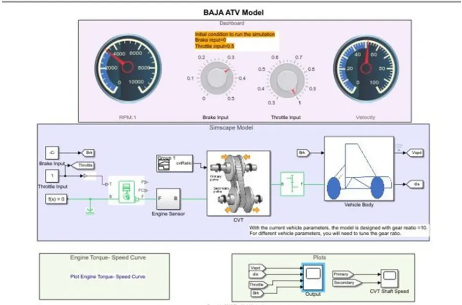
VEHICLE SPEED vs THROTTLE vs BRAKE vs DISTANCE
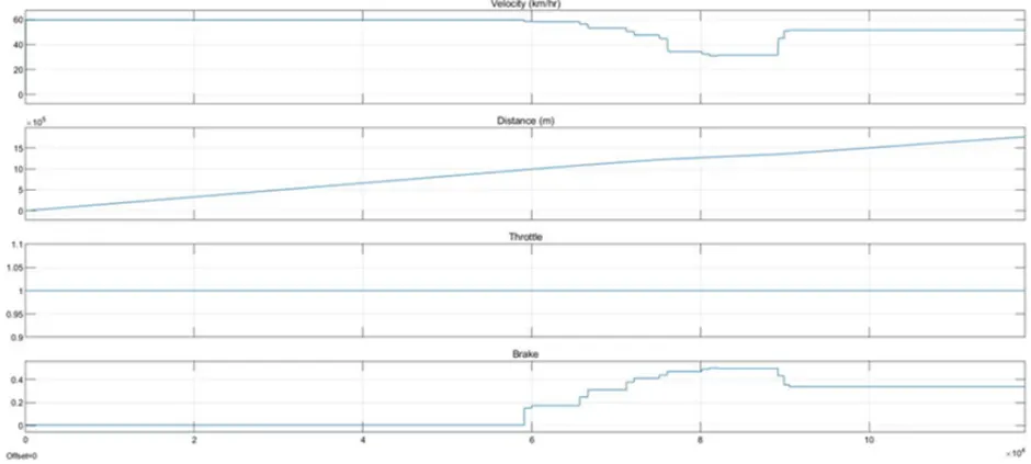
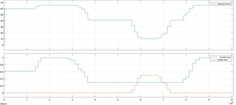
The vehicle speed is been varied according to the dashboard knob of speed and braking which results in the graph that it can see that brake and vehicle velocity is inversely proportional.
CVT PRIMARY AND SECONDARY RPM:
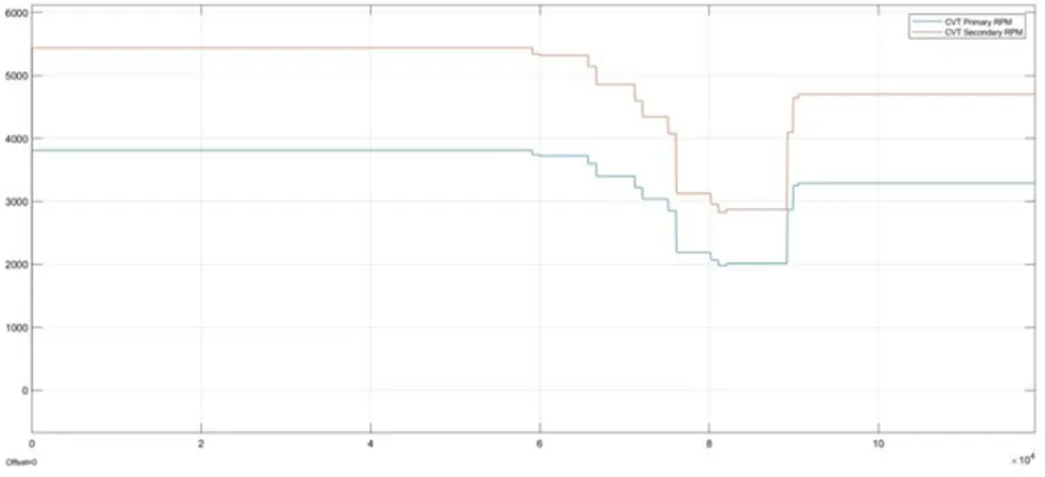
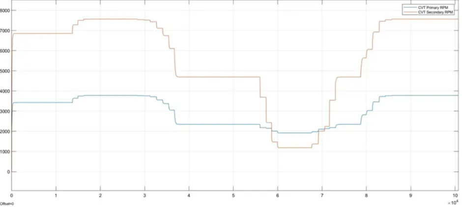
The RPM of CVT both primary and secondary is deduced that the primary rpm is higher than the secondary cvt to reduce the speed.
STUDY 2:
BAJA ATV model with Continuously Variable Transmission (CVT) USING Look up table.
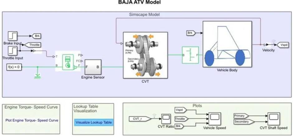
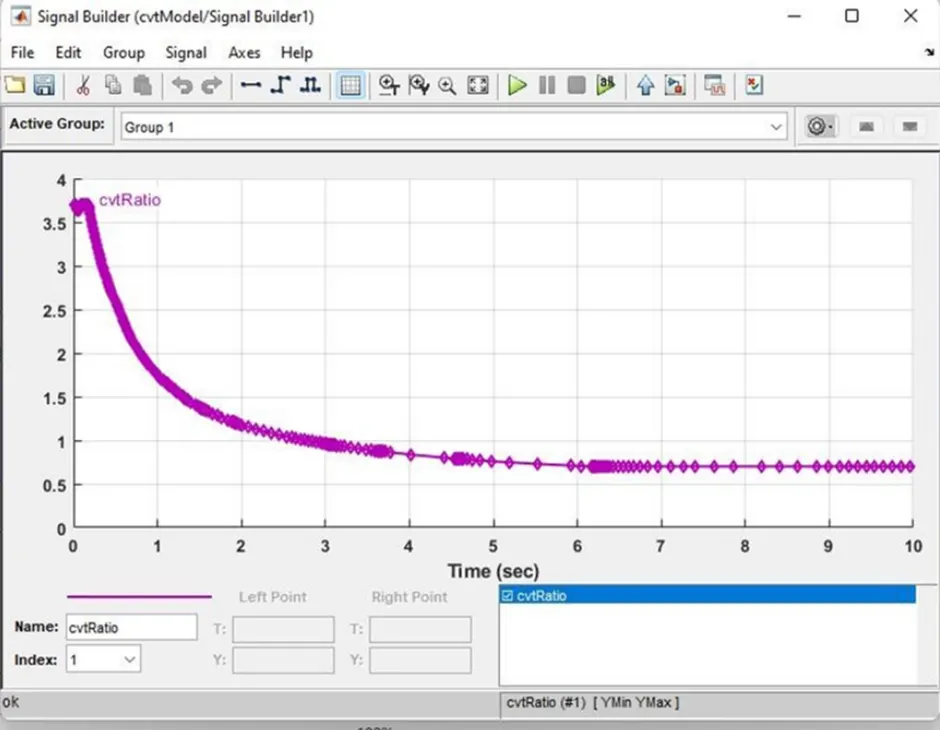
The main difference between the previous and present model is its input for cvt gear ratio using lookup table, where rest remains same.
LOOKUP UP TABLE
Look up table is a predefined data fed to the model that contains numerous data with them.
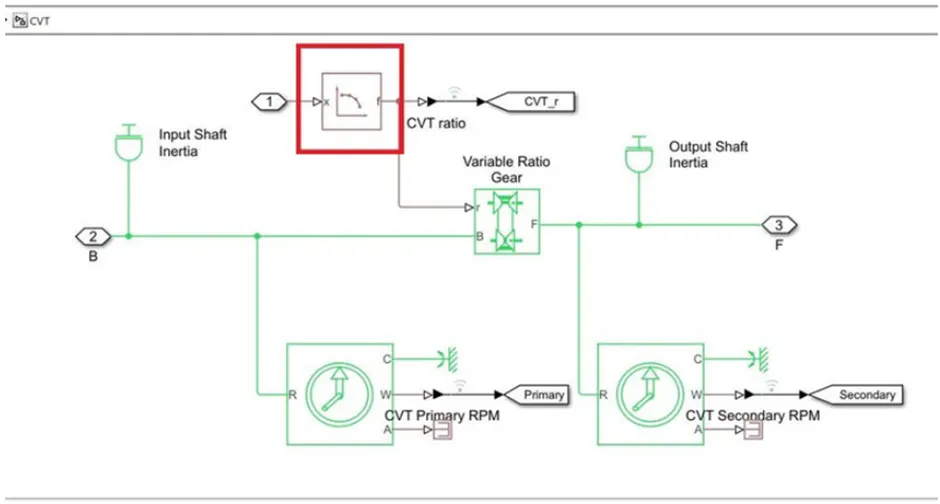
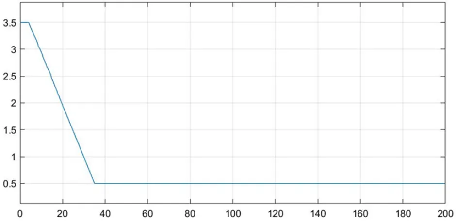
-LOOK UP TABLE
Look up table is a predefined data fed to the model that contains numerous data with them
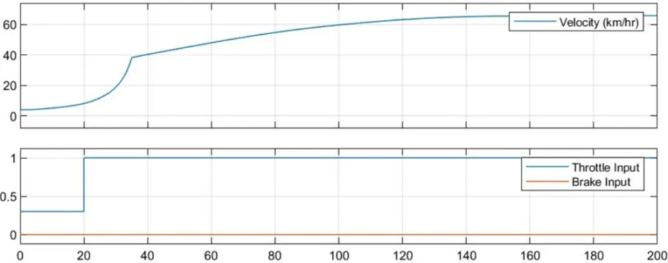
VEHICLE SPEED AND THROTTLE INPUT VS BRAKE INPUT
The brake input is remained to zero that it can be seen from graph and the speed is been increased according to look up table produced, vehicle reaches the top speed 160secs
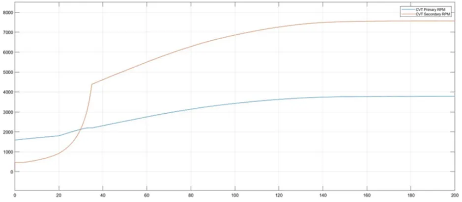
CVT SHAFT RPM:
t rpm both primary and secondary are relatively same as to the vehicle velocity that primary shaft is to reduce the speed to secondary.
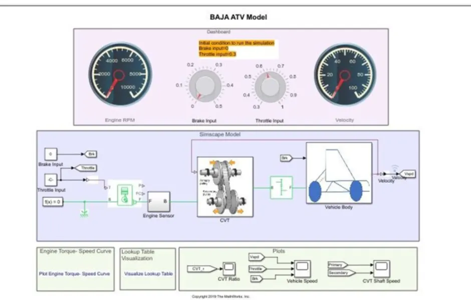
CASE 2: BAJA ATV model with continuously Variable Transmission (CVT) USING LOOK UP With DASHBOARD
MODEL
VEHICLE SPEED AND THROTTLE VS BRAKE INPUT:
CVT SHAFT RPM PRIMARY VS SECONDARY:
CONCLUSION:
Thus, we have successfully studied the 4 cases involved in the BAJA ATV WITH CVT accordingly with input throttle and brake and studied about vehicle speed and cvt shaft rpm.