Project
System-level simulation of an all-terrain vehicle
Aim of Project: Prepare a technical report explaining the model properties & comments on the results
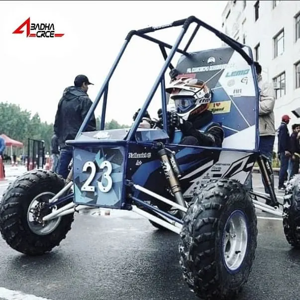
Main Parts:
Mechanism of BAJA ATV model1 when the brake input is zero with respect to time :
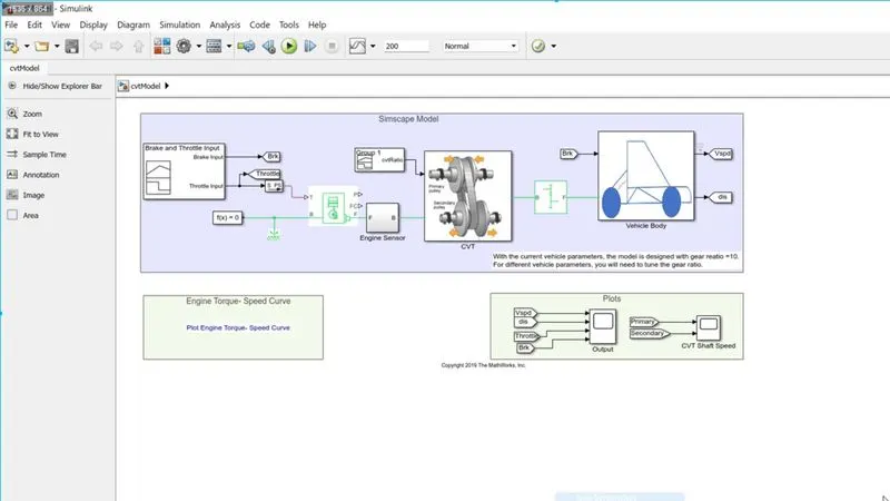
There are many things which I can explain (ex, All SimScape model) but that is not necessary. I will explain how Output is coming by Scope and why values are varying.
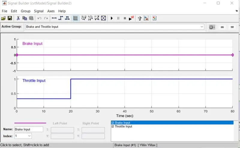
Signal Builder of Brake and Throttle :
First, I have predefined the Brake and throttle Input values with respect to the time and put out the 2 GOTO ports for the vehicle and Engine respectively. this port is sent into Scope also.
Engine :
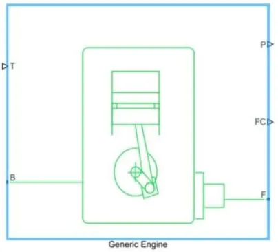
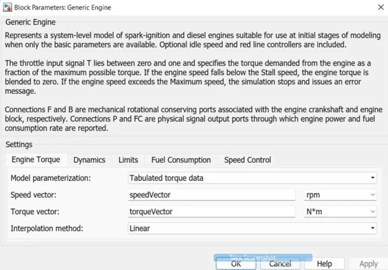
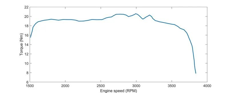
the engine drives the continuous variable transmission(CVT) and the input of the engines is taken from Workspace (which is available in the speed and torque vector diagram) and throttle input from the signal generator.
From port F of the engine, we get rotation which is rotated CVT and we get the variation from engine speed to CV Transmission system speed.
Continuous Variable Transmission (CVT) : 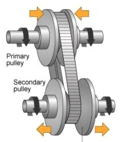
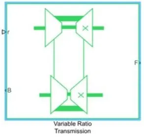
This transmission system creates the revolution speed difference between engine output and gearbox input shaft which varies continuously according to the human input parameters.
For driving the CVT we have to send the physical signal which is nothing but cvtRatio (input to output shaft velocity) and import it from the spreadsheet file data.
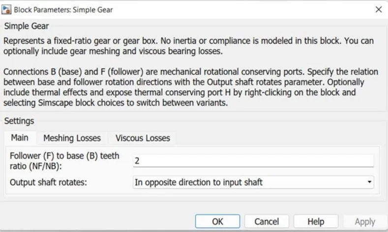
Simple Gear :
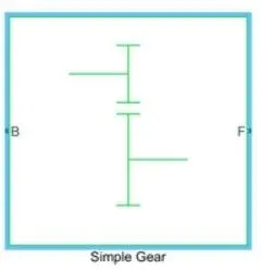
Gear is increased or decreased in the rotation speed due to gear ratio and there is no effect in transferring the power between two shafts.
Vehicle Body :
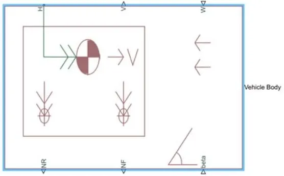
block accounts for body mass, aerodynamic drag, road incline, and weight distribution between axles due to acceleration and road profile.
Connection H is the mechanical translational port joined with the horizontal motion of the vehicle body. The resulting traction motion developed by tires should be connected to this port. Connections V, NF, and NR are physical signal output ports for vehicle velocity and front and rear normal wheel forces, respectively. Wheel forces are considered positive if acting downwards. Connections W and beta are physical signal input ports which are headwind speed and road inclination angle, respectively.
Tires :
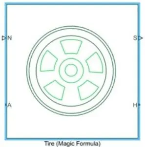
Tires are fitted in the vehicle body Left/right rear and front wheel and change the rotational motion to translation motion. Connection A is the mechanical rotational conserving port for the wheel axle.
Connection H is the mechanical translational port for the wheel hub through which the thrust is developed by the tire and applied to the vehicle. Connection N is a physical signal input port that applies the normal force acting on the tire. Connection S is a physical signal output port which reports the tire slip.
Double shoe break :
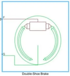
break device is generate the deacceleration in the vehicle so that the vehicle can stop which is actually a frictional device.
------------------------------------------------------------------------------------------------------------------------------
Output:
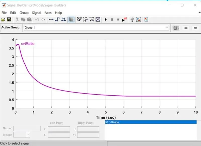
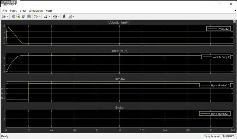
In the time of less than 1 second, there is a peak of cvtRatio which means the Vehicle velocity will monotonically increase. after that, there is an exponentially fall in cvtRatio which means vehicle velocity will negative exponentially decrease.
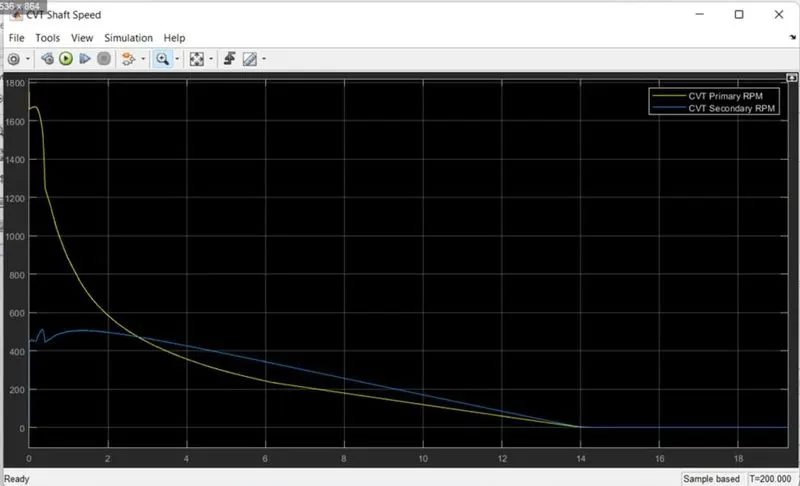
So, in this interval, the vehicle has travelled the distance (above 10 meters) and after achieving zero velocity vehicle travelled no more distance.
==============================================================================
Mechanism of BAJA ATV model2 when the brake and throttle input value can be manually varied:
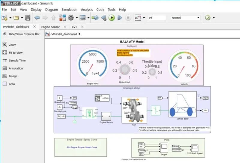
You can see in the above diagram that there are 2 knobs which are for throttle and brake input. All operations are the same as a first case but here are 4 conditions:
CONDITION 1: If the Break knob is constant at 0 and the throttle knob is varying to their value then the Results are given below:
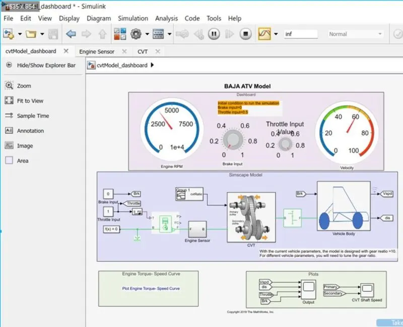
Here you can see how the Engine is operating and giving the 60 km/hr speed and the travelled distance by the vehicle.
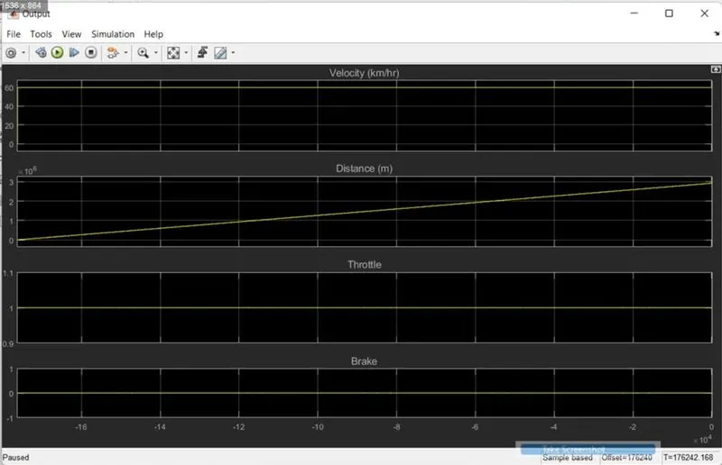
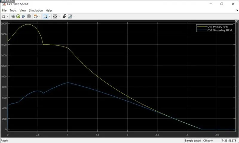
Both Primary and secondary RPM of CVT became zero in very less time.
The throttle valve value decreased by 0.5 from the knob and the result is that the speed was <60 and the engine RPM reduced.
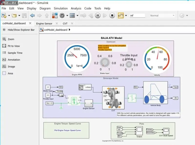
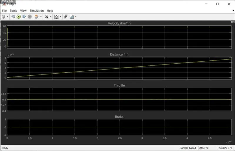
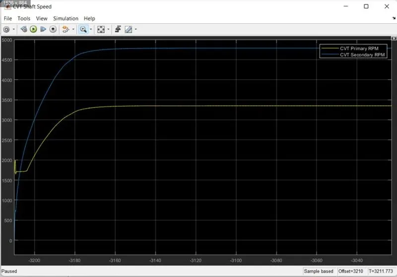
You can see below that how the CV transmission primary and second pulley RPM is varying.
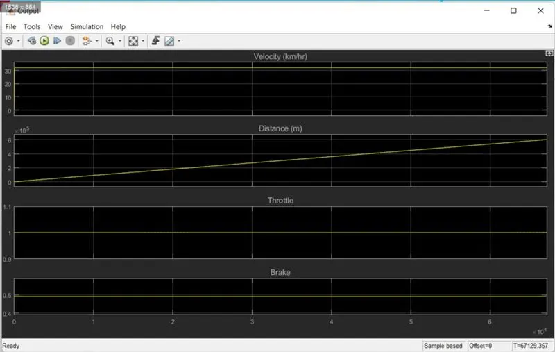
CONDITION 2: If the Throttle knob is constant and the brake knob is varying to their value then the Results are given below:
All mechanisms are the same as in the previous model and now here we are studying what will be the behaviour of the vehicle if I increase or decrease the braking intensity.
If I increase the intensity of the brake then the engine speed and velocity of the vehicle will decrease and vice versa.
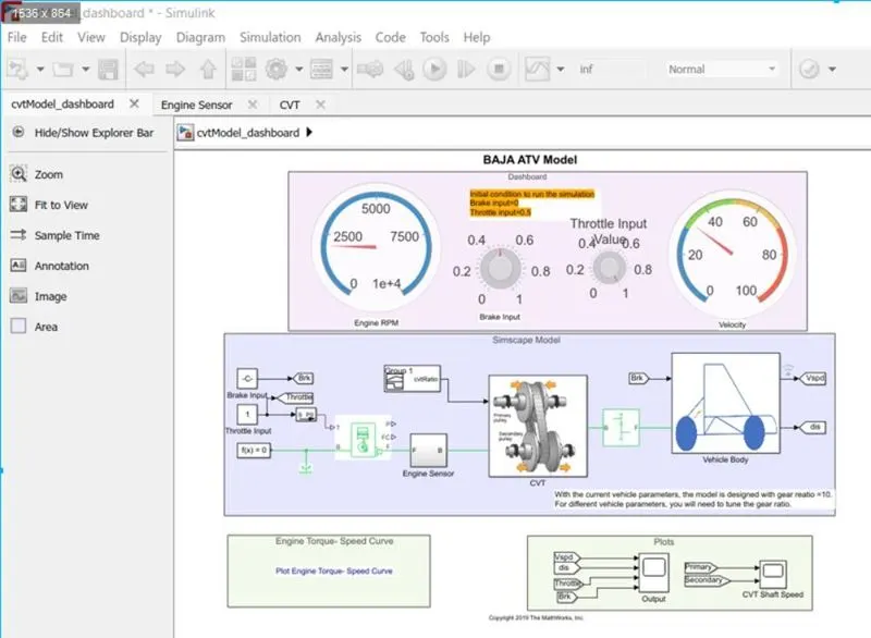
After applying the brake, the velocity of the vehicle becomes low in comparison to the zero brake condition. The travelling distance is increasing at a constant speed.
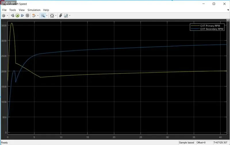
CVT primary and secondary RPM: Here we can easily see how the primary pulley of CVT revolution speed increased firstly after sometime later revolution speed decreased and the Secondary pulley of CVT revolution has crossed the speed of primary.
CONDITION 3: If the Throttle knob and the brake knob is varying to their value then the Results are given below:
If I vary the intensity of throttle input and brake input then for a short time the Engine operates but after a few seconds it will stop so the vehicle will not travel longer.
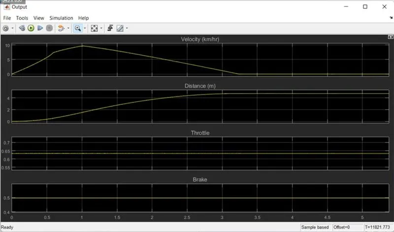
The below diagram shows that if I vary both parameters (Throttle and Brake input) then the CV transmissions speed input and output will become zero after some time because Engine did not have the operating condition.