Project
Report
Aim of the project
The main aim of the project is system level study and stimulation the BAJA -ATV model. And also, we study about the components used, detailed study of the vehicle model and stimulation in cooperate with the CVT and some key take away.
AVT (All-Terrain Vehicle)
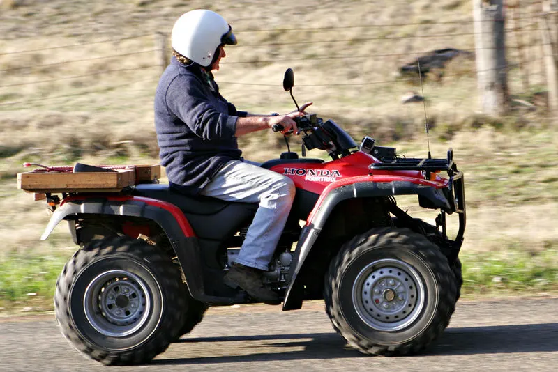
An all-terrain vehicle is defined as the off-highway vehicle designed to travel on four low-pressure or non-pneumatic tires, having a seat designed to straddled by the operator and handlebars for steering control.
The main component of AVT is vehicle body, suspension system, tire, engine and CVT.
The CVT (continuously variable transmission) does not use gears like a typical transmission. Rather, it uses two pulleys connected by a belt with infinite gear ratio. It’s a little bit like a snowmobile transmission.
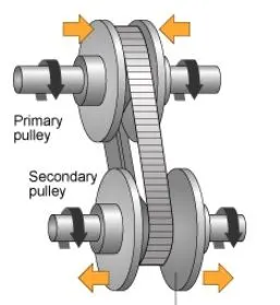
CVT consist of primary pully, secondary pully variator and belts. When the primary pully moves outward and the variator of the secondary pully moves inward and thus speed reduction will take place and if vice versa happened overdrive will happen.
DESCRIPTION
As we know about the AVT system now we are going to study about the system-level BAJA AVT system that stimulate using Simulink. Let us study about each system in detail
As in the physical system the stimulation mode consists certain block such as:
GENERIC ENGINE
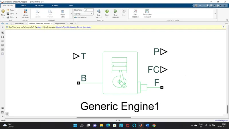
The generic engine block represents a general internal combustion (IC) engine, which is a type of spark ignition (SI-petrol) or compression ignition (CI-diesel). The speed torque and speed parameters are provided.
PORTS
- B- Rotational conserving port representing the engine block.
- F-Rotational Conservation port representing the engine crankshaft.
- T-Physical signal input port specifying the normalized engine throttle level
- P-Physical signal output port reporting the instantaneous engine power, in Watts(W)
- FC- physical signal input port reporting the fuel consumption, in kg/s
SIMPLE GEAR
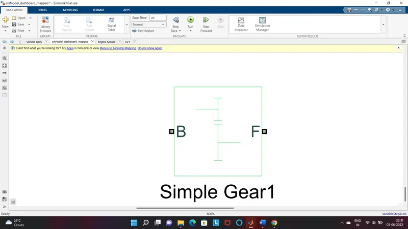
The gear is the combination of a driver and driven gear where the speed is reduction by the gear ratio
PORTS
- B- Base gear or driver gear
- F- follower gear
CVT
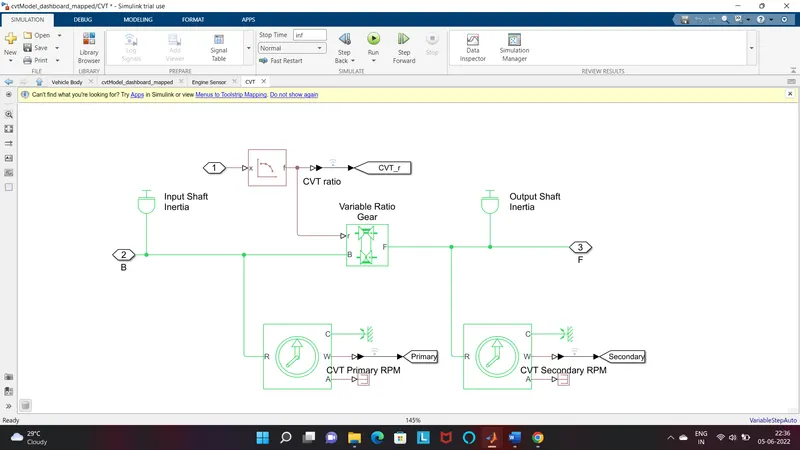
The system contains
- Input/output shaft inertia.
- Variable ratio gear.
- Two motion sensors for primary and secondary.
PORTS
- B-base pulley or drive pully
- F-follower pully or driven pully
- r- Variable transmission ratio(input)
VEHICLE BODY
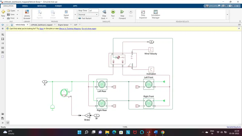
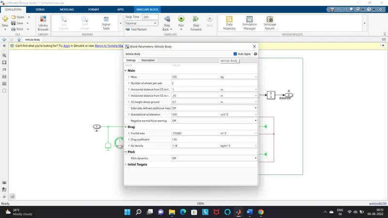
Two- axle vehicles with longitudinal dynamics and motion and adjustable mass, geometry and drag properties. the vehicle can have the same or a different number of wheels on each axle. For example, two wheels on the front axile and one wheel on the rare axle. the vehicle wheels are assumed identical in size. The vehicle can also have a centre f gravity cg that is or below the plain travel
PORTS
- NR- Rear Axle normal force(N)
- NF-front axle normal force (N)
- Beta- Road incline angle (rad)
- V- longitudinal velocity (m/s)
- W – head wind speed(m/s)
- H – horizontal motion
DOUBLE SHOE BREAK
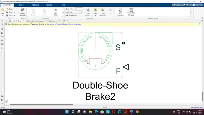
The double shoe breke block represents a frictional brake with two pivoted rigid shoes that press against a rotating drum to produce a braking action. The rigid shoes sit inside or outside the rotating drum in a diametrically opposed configuration. A positive actuating force causes the rigid shoes to press against the rotating drum. Viscous and contact friction between the drum and the rigid shoe surface cause the rotating drum to decelerate.
PORT
- S- rotational conserving port associated with the rotating drum shaft
- F – physical signal input port associated with the applied actuating force
TIRE
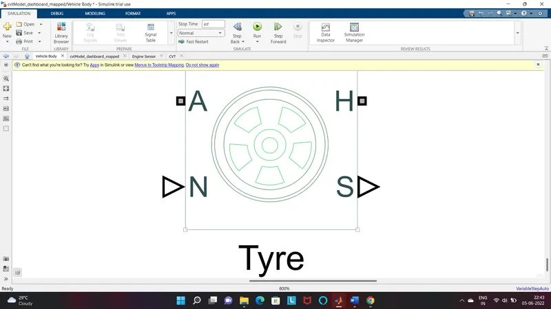
The vehicle body is connected to 4 tires each per axle to move the vehicle according to the input to the axle.
PORTS
- N – normal force
- S – tire slip
- A- Axle
- H – mechanical translational associated with the wheel hub that transmit the trust generated by the tire to the reminder of the vehicle.
ENGINE SENSOR
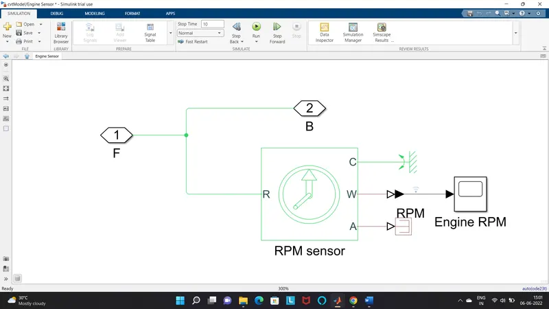
This block measure angular velocity or angle in a mechanical rotational network. The sensor is ideal since it does not account for inertia, friction, delays, energy consumption, and so on.
The physical signal ports W and A report the angular velocity and angular displacement respectively, of port R relative to port C. The measurement is positive when the motion at R is greater then motion of C.
BLOCK USED:
- Signal Builder – To input the break, throttle and CVT ratio.
- Simulink to PS converter – To convert the Simulink signal to simscape environment.
- Solver configuration – To specify the solver parameter before starting the stimulation.
- Mechanical Reference – To make sure all the components are clamped to the ground
- Generic engine – To run the engine with speed and torque values as input.
- PS to Simulink converter – To convert simscape signal to Simulink environment.
- Scope - To view graph of the parameter for better understanding.
- Display – To view the calculated engine power.
- Inertia – To represent the solid inertia.
- Rotational Motion Sensor – To sense the rotational motion from the engine and give output as RPM.
- Variable Gear Ratio – To vary the speed according to the gear ratios.
- Ps terminator – Terminate for unconnected signal outputs.
- Double shoe break – To apply break to the vehicle when needed.
- PS Constant – Generate constant physical signal.
- Tire – For transporting the vehicle.
- Rotational free end – For mechanical component(tire).
- Vehicle body – To represent the BAJA ATV model body.
- Custom measure gauge – To measure the break and throttle input.
- Knob – To increase, decrease and vise versa of throttle and break inputs.
- Lookup table – to increase the CVT value from the workspace.
- Simple gear – To reduce the speed of the engine with pre-defined gear ratio.
- Step – To increase or decrease an input value for a defined time interval
TYPE OF MODEL:
- BAJA ATV model without Dashboard
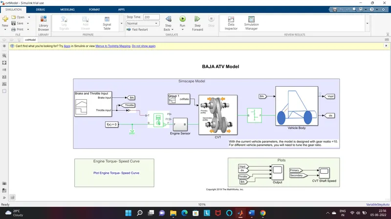
STIMULATION PROCESS
BREAK,THROTTLE AND CVT RATIO input and stimulation time is 200sec.
- The throttle signal is generated by the signal builder block and inputted to generic engine.
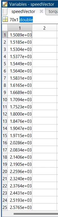
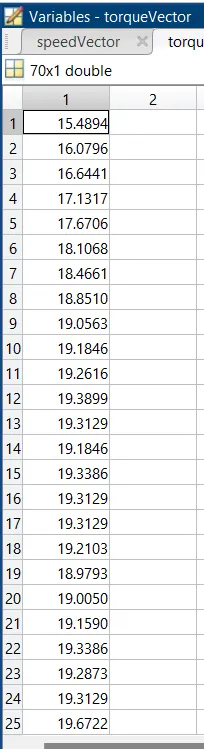
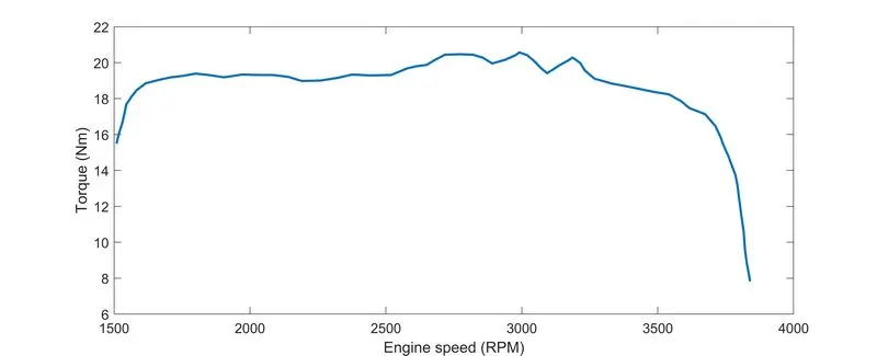
- The torque and speed vector are inputted from the MATLAB workspace
- The engine will generate the output RPM which can be taken from the crankshaft output. This output RPM is sense by the ideal rotational motion sensor to get the speed.
- The initial input should same as given
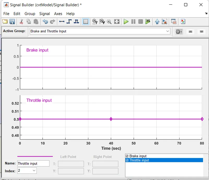
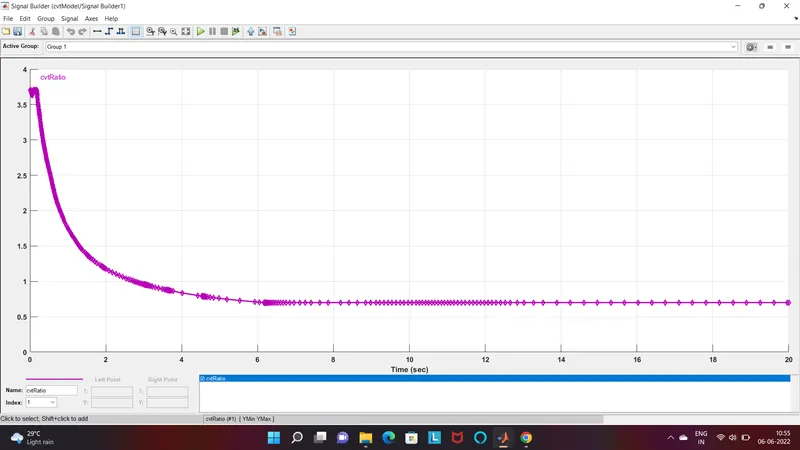
CVT input
- Then the output is given to the CVT transmission the gear ratio is as shown in the below
RESULT IN SCOPES
Without changing the input ans stop time is 200sec ,the result is as shown below;
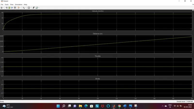
The velocity is increasing upto 40 sec and then increase in constant rate,the distance is increasing with time ,the thottle is 0.5 constant and zero brake presure is applied
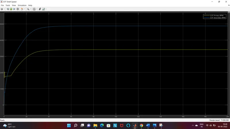
Initialy the secondary CVT RPM is low and primary CVT RPM is high, in order to attain high torque for initial pick up after that the speed increases by attaining high RPM in secondary CVT then become constant speed of 60 km/hr
- BAJA ATV model with dashboard
The only diffrence here is the additional dashboard contains ,inputparameters and guage meters instread of signal builder. And have stop time in infinite,and accelerate and decelerate the throttile and apply the brake too. Then run,
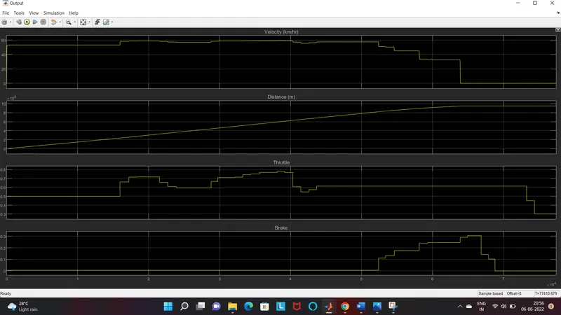
In small instant time itself the secondary CVT can able to attain high rpm
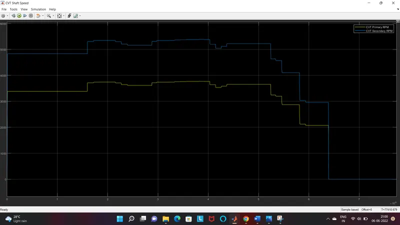
- BAJA ATV model – Mapped lookup table with dashboard
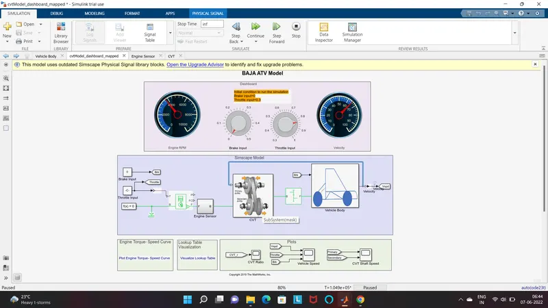
In this model a lookup table vishualization is available which represents the CVT gear ratio and velocity of vehicle
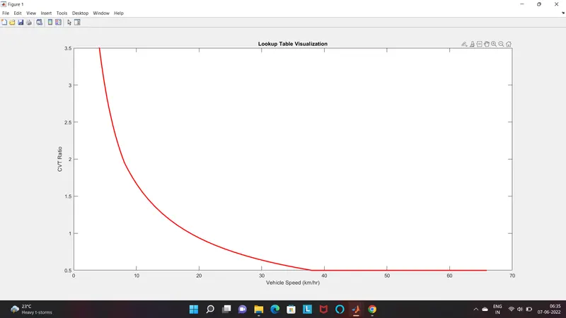
Other all setups are same except a additional connection with vehicle body and CVT gear ratio.
Conclustion
From this stimulation, we have seen the effect of throttle ,break and CVT gear ratio in the vehicle speed,torque,velocity of a ATV through the system level stimulation