Project
Aim: To carry out a system-level simulation of an all-terrain vehicle and to write a detailed report.
ALL-TERRAIN VEHICLE:
According to the American National Standards Institute (ANSI), an all-terrain vehicle (ATV), also known as a quad (cycle), three-wheeler, four-track, four-wheeler, or quadricycle, is a vehicle that travels on low-pressure tires and has a seat that is straddled by the operator, as well as handlebars for steering control. It's built to tackle a broader range of terrain than most other vehicles.
BAJA ATV (SAE):
The BAJA SAE Series is a global event conducted by the Society of Automotive Engineers, USA, for undergraduate engineering students. In 1976, at the University of Carolina, the tournament was first known as Mini BAJA. The event has now expanded to six countries: the United States, Mexico, South Africa, Korea, Brazil, and India. The BAJA SAE challenges students to design, fabricate, and validate a single-seater four-wheeled off-road vehicle to participate in a series of events over the course of three days that test the vehicle for sound engineering practices, agility in terms of gradeability, speed, acceleration, and maneuverability characteristics, and finally its ability to withstand the elements.
Description:
Generic Engine:
A generic internal combustion engine is represented by the Generic Engine block. This block is suited for both spark-ignition and diesel engines. Parameterizations for speed-power and speed-torque are available. The normalized engine torque is specified via a throttle physical signal input. Crankshaft inertia and response time lag are two dynamic factors that can be selected. Based on the fuel consumption model you select, a physical signal port outputs the engine fuel consumption rate.
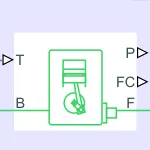
PORTS:
- B - Rotational Conserving Port representing the Engine Block
- F - Rotational Conserving Port representing the Engine crankshaft
- T - physical signal input port specifying the normalized engine throttle level
- P - Physical signal output port reporting the instantaneous engine power, in W
- FC - Physical signal output port reporting the fuel consumption rate, in kg/s
The simple gear is a combination of a driver and driven gear where the speed is reduced by the gear ratio.

Ports:
- B-Base Gear or Driver Gear
- F-Follower Gear or Driver Gea
CVT TRANSMISSION:
In CVT (Continuous Variable Transmission) the variable diameter pulley plays a vital role in transmission. Variable diameter pulleys must always come in pairs. One of the pulleys, known as the drive pulley (or driving pulley), is connected to the crankshaft of the engine. The driving pulley is also called the input pulley because it's where the energy from the engine enters the transmission. The second pulley is called the driven pulley because the first pulley is turning it. As an output pulley, the driven pulley transfers energy to the driveshaft.
The distance between the center of the pulleys to where the belt makes contact in the groove is known as the pitch radius. When the pulleys are far apart, the belt rides lower and the pitch radius decreases. When the pulleys are close together, the belt rides higher, and the pitch radius increases. The ratio of the pitch radius on the driving pulley to the pitch radius on the driven pulley determines the gear when the pitch radius is small on the driving pulley and large on the driven pulley, then the rotational speed of the driven pulley decreases, resulting in a lower "gear" When the pitch radius is large on the driving pulley and small on the driven pulley, then the rotational speed of the driven pulley increases, resulting in a higher "gear" Thus, in theory, a CVT has an infinite number of 'gears that it can run through at any time, at any engine or vehicle speed.
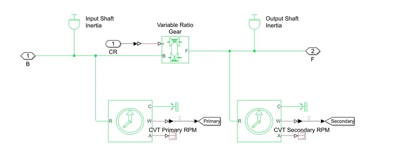
PORTS:
- Driven Pulley B-Base Pulley or Drive Pulley
- F- Follower Pulley or Driven Pulley
- r-Variable Transmission Ratio (Input)
VEHICLE BODY :
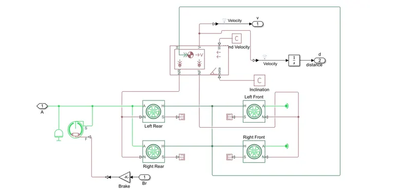
A two-axle vehicle with longitudinal dynamics and motion and adjustable mass, geometry, and drag properties. The vehicle can have the same or a different number of wheels on each axle. For example, two wheels on the front axle and one wheel on the rear axle. The vehicle wheels are assumed identical in size. The vehicle can also have a centre of gravity (CG) that is at or below the plane of travel.
PORTS:
- NR-Rear Axle Normal Force (N)
- NF-Front Axle Normal Force (N)
- Beta-Rood incline Angle (rod)
- V Longitudinal Velocity (m/s)
- W-Head Wind Speed (m/s)
- H-Horizontal Motion
case 1:
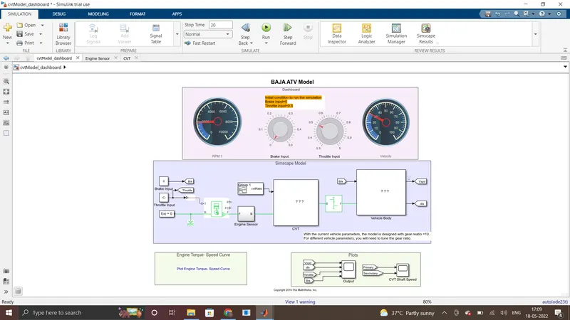
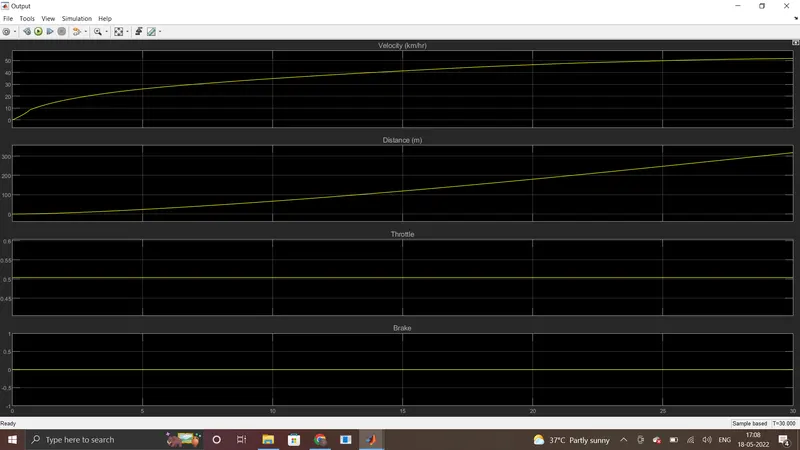
- This is a default case in which brake and throttle input is applied by default. Here, Throttle input is 0.5, and Brake input is zero which means no braking condition is applied and the simulation run time is 30 seconds.
-
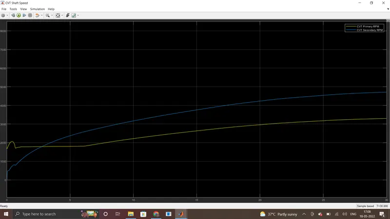
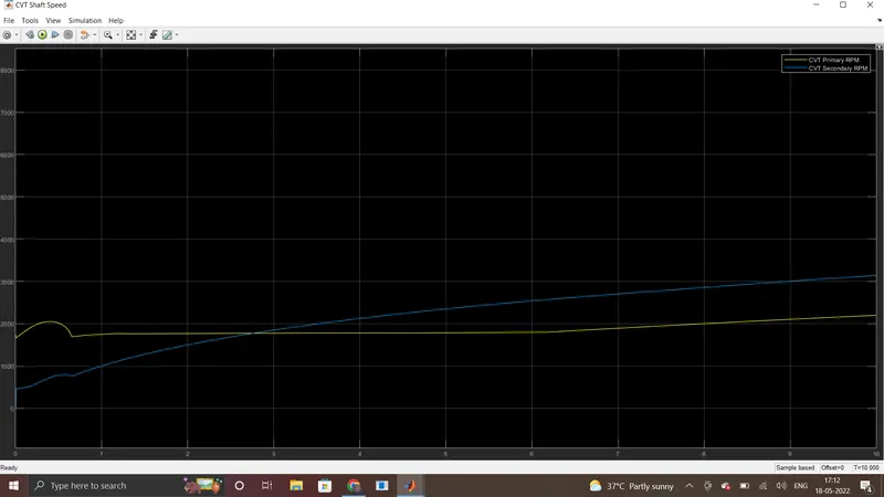
The simulation output is gotten from the last Simulink area box. There are two scopes, one is to give information about velocity(or vehicle speed), distance, throttle, and brake output. The second is to give information about CVT Shaft Speed.
-
Here, the Vehicle moves more than 300m in 30sec. with a max velocity of the vehicle is nearly 52km/hr RPM and Velocity is gradually increased with respect to time
Case 2:
- In this case, Throttle input is maximum and Brake input is also maximum which means full braking and acceleration condition is applied and the simulation run time is 30 seconds.
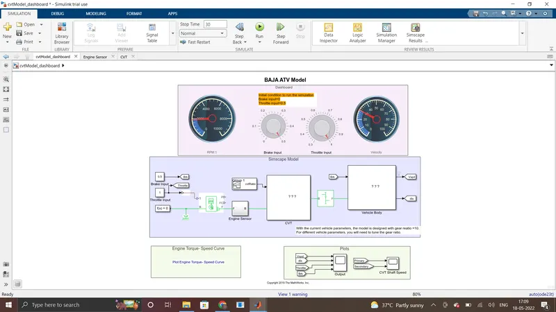
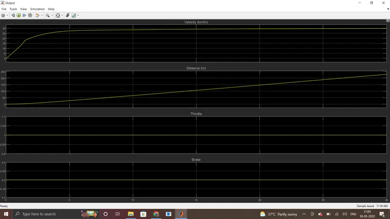
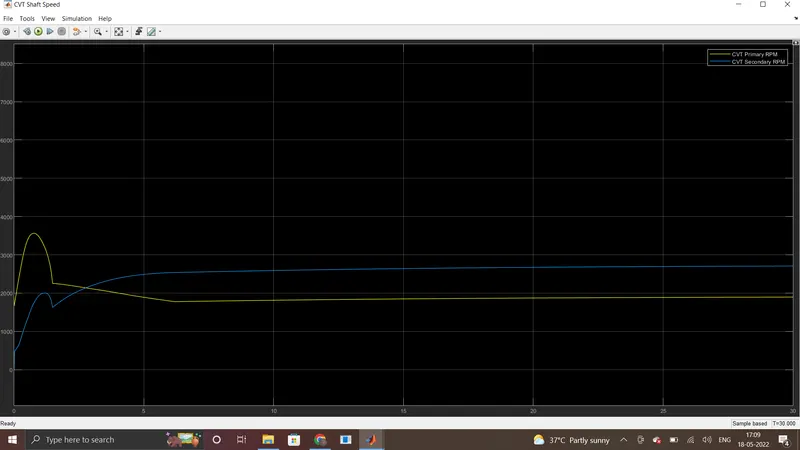
- The simulation output is gotten from the last Simulink area box. There are two scopes, one is to give information about velocity(or vehicle speed), distance, throttle, and brake output. The second is to give information about CVT Shaft Speed.
- Here, the Vehicle moves nearly 225m in 30sec. with a max velocity of the vehicle is nearly 30km/hr Velocity is gradually increased at starting point and then it makes constant (at 30km/hr) with respect to time.
case 3:
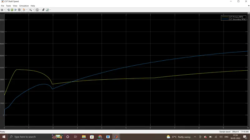
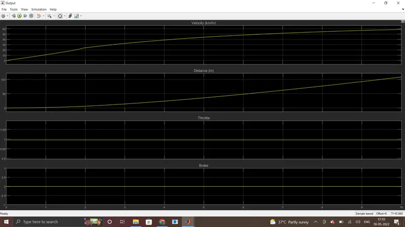
- In this case, Throttle input is maximum and Brake input is zero which means no braking condition is applied and full acceleration condition is applied and the simulation run time is 10 seconds.
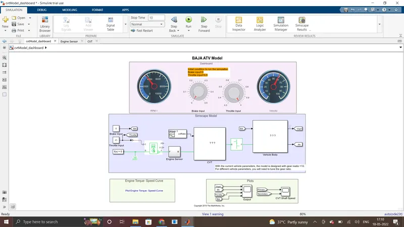
- The simulation output is gotten from the last Simulink area box. There are two scopes, one is to give information about velocity(or vehicle speed), distance, throttle, and brake output. The second is to give information about CVT Shaft Speed.
- Here, the Vehicle moves more than 100m in 10sec. with a max velocity of the vehicle is closer to 60km/hr. RPM and Velocity are gradually increased with respect to time.
Case 4:
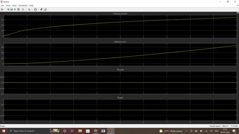
- Here, Throttle input is 0.5 and Brake input is zero which means no braking condition is applied and the simulation run time is 10 seconds.
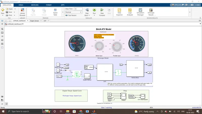
- The simulation output gets from the last Simulink area box There are two scopes, one is to give information about velocity(or vehicle speed), distance, throttle, and brake output. The second is to give information about CVT Shaft Speed.
- Here, the Vehicle moves less than 70m in 10sec. with a max velocity of the vehicle is nearly 35 km/hr. RPM and Velocity are gradually increased with respect to time.
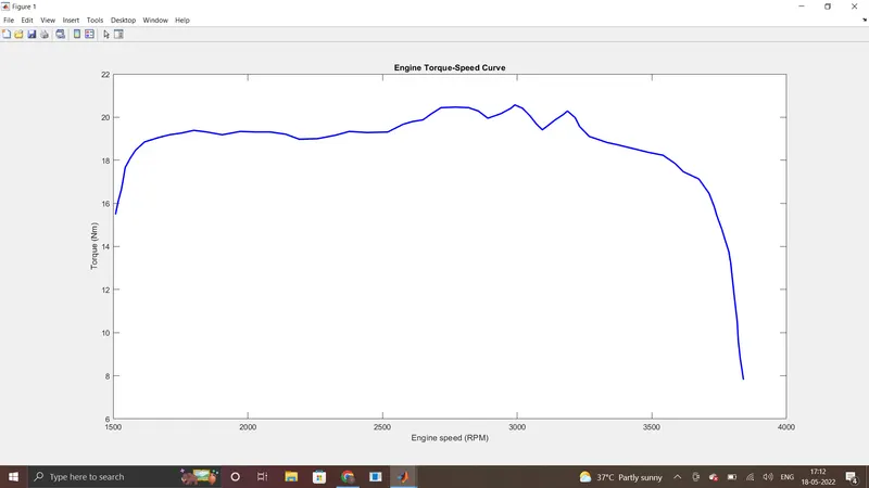
- This is Engine torque-speed curve.
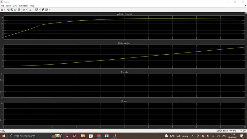
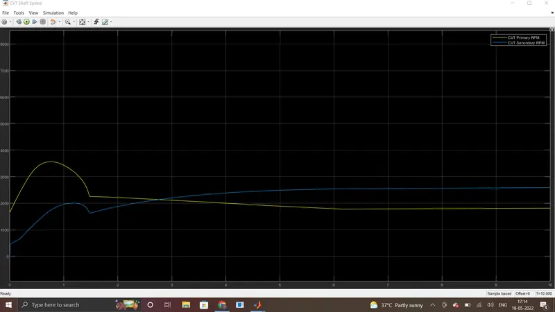
Case 5 :
- In this case, Throttle input is maximum and Brake input is also maximum which means full braking and acceleration condition is applied and the simulation run time is 10 seconds.
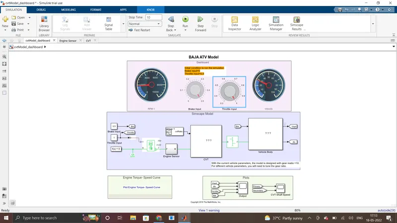
- The simulation output is get from the last Simulink area box. There are two scopes, one is to give information about velocity(or vehicle speed), distance, throttle, and brake output. The second is to give information about CVT Shaft Speed
- Here more than 65m in 10sec with a max velocity of the vehicle is nearly 28 km/hr Velocity is gradually increased at the starting point and then it moke constant (at 28km/hr) with respect to time