Project - all terrain vehicle
ALL TERRAIN VEHECLE SIMULATION
AIM:-
Carry out a system-level simulation of an all-terrain vehicle.
THEORY:-
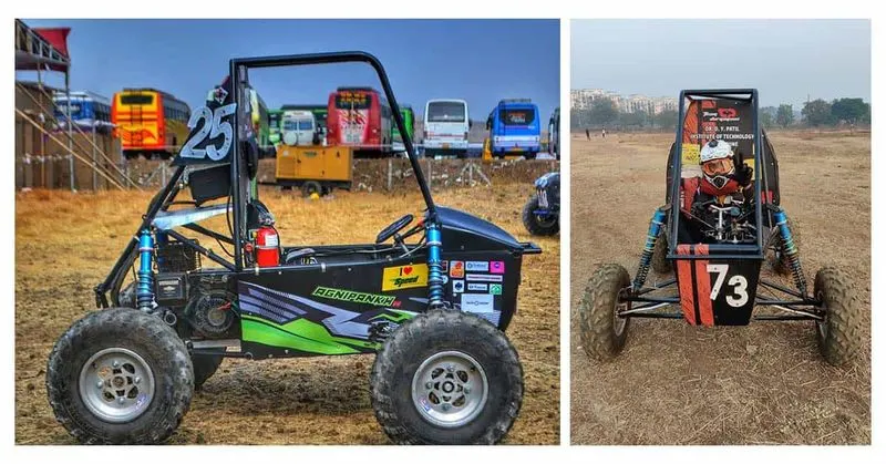
ATV:An all-terrain vehicle (ATV) is defined as a motorized off-highway vehicle designed to travel on four low-pressure or non-pneumatic tires, having a seat designed to be straddled by the operator and handlebars for steering control. ATVs are subdivided into two types as designated by the manufacturer. Type I ATVs are intended by the manufacturer for use by a single operator and no passenger. Type II ATVs are intended by the manufacturer for use by an operator and a passenger, and are equipped with a designated seating position behind the operator.
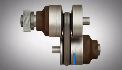
CVT: A continuously variable transmission (CVT) is an automatic transmission that can change seamlessly through a continuous range of gear ratios. This contrasts with other transmissions that provide a limited number of gear ratios in fixed steps. The flexibility of a CVT with suitable control may allow the engine to operate at a constant RPM while the vehicle moves at varying speeds.
SIMULINK MODELS :-
There are different types of models of ATV in the reference link . there is open loop model as well as closed loop model with and without dashboard . so we will be studying and simulating different models and providing their inputs and results .
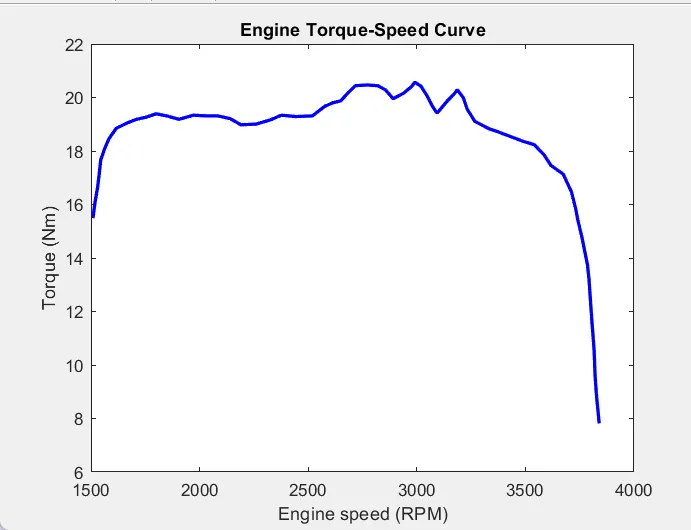
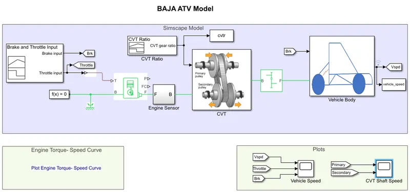
These models show how to build an ATV with CVT which is mostly used in BAJA competitions. Simscape and Simscape Driveline have been used to complete the system. The engine data used in the model is provided as an image which shows the Engine Speed (RPM) Vs Torque curve.
Model 1 : cvtModel
Contains Simscape model of BAJA ATV with Continous Variable Transmission.
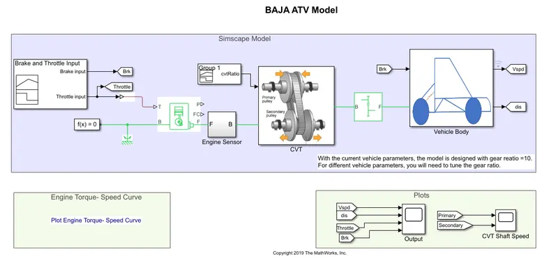
the model consist of following blocks and subsystems
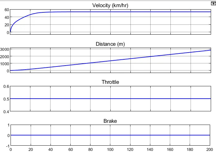
Signal Builder :Create and generate interchangeable groups of signals whose waveforms are piecewise linear. we are using signal builder to give Brake and throttle input . brake input is 0 and throttle input is 0.5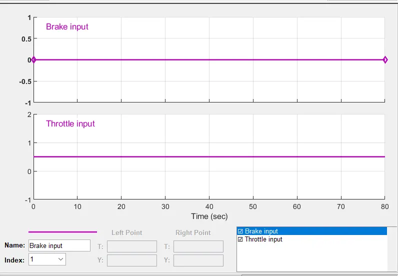
Generic Engine : Represents a system-level model of spark-ignition and diesel engines suitable for use at initial stages of modeling when only the basic parameters are available. the parameter given to engine is given below .
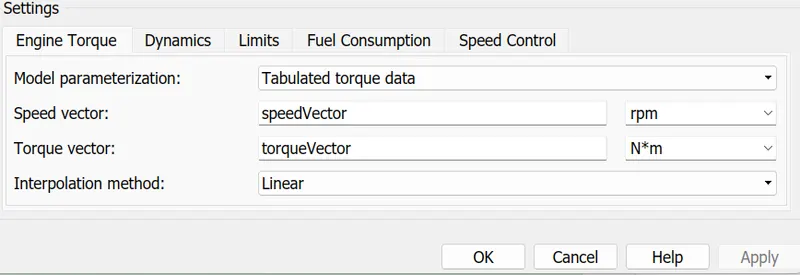
the speed vector and torque vector is given in workspace
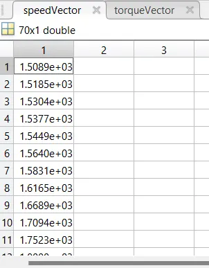
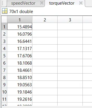
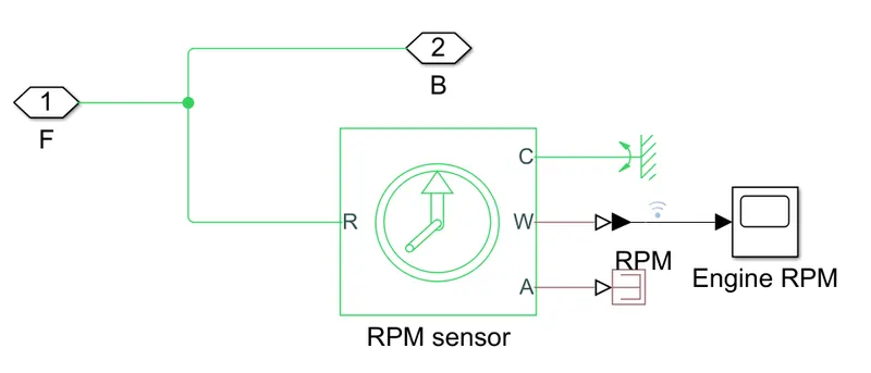
Engine sensor : this is a subsystem block. this is used to sense engine rpm with help of rpm sensor block.
Engine torque - Speed curve : the engine data used in the model is provided as an image .
CVT : CVT is a subsystem block . this block is the CVT (continously variable transmission ) system in ATV model .
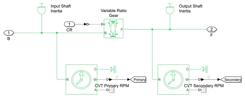
the blocks in this subsystem include
- Variable Ratio Gear : Represents a variable ratio gearbox such as implemented by mechanical belt CVT, electric, or hydraulic transmissions. The physical signal input r defines the ratio of input to output angular shaft velocities.
- Inertia : The block represents an ideal mechanical rotational inertia. we use two inertia block to represent input and output shaft .
- Ideal rotational motion sensor : we use two of these blocks to measure rpm of input and output shafts .
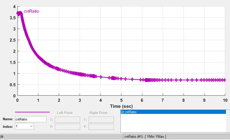
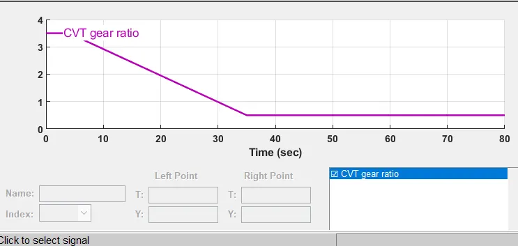
Signal Builder - cvt ratio : signal builder is used to create different cvt ratio to fed into variable ratio gear
Simple gear : Represents a fixed-ratio gear or gear box. No inertia or compliance is modeled in this block. Connections B (base) and F (follower) are mechanical rotational conserving ports. output shaft rotates in the same direction as of input shaft . the gear ratio is 10 .
Vehecle body : the vehecle body is a subsystem block .
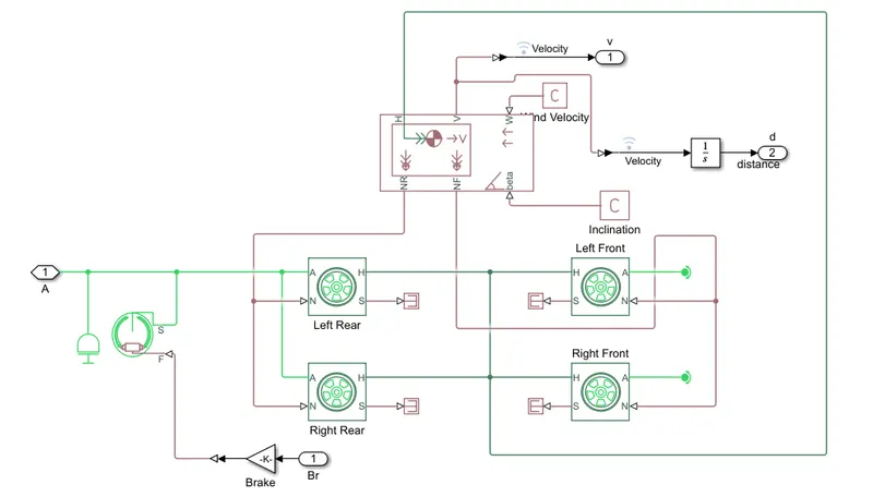
the main blocks in this subsystem are :
- Vehecle body : Represents a two-axle vehicle body in longitudinal motion. The block accounts for body mass, aerodynamic drag, road incline, and weight distribution between axles due to acceleration and road profile. the parameters for vehecle body are given below
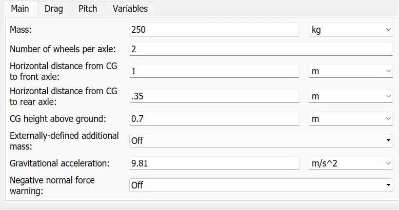
- Tire (Magic formula) : Represents the longitudinal behavior of a highway tire characterized by the tire Magic Formula. The block is built from Tire-Road Interaction (Magic Formula) and Simscape Foundation Library Wheel and Axle blocks . we are using 4 tire blocks in total .
- Double shoe brake : Represents a brake arranged as two pivoted rigid shoes symmetrically installed inside or outside a drum and operated by one actuator. The actuator force causes the shoes to exert a friction torque on a shaft connected to the drum. rear wheel blocks are connected to this block .
RESULTS of model 1:
Engine RPM plot
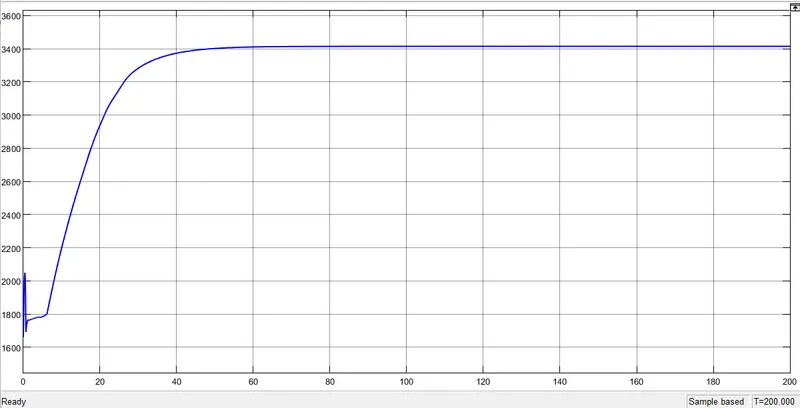
- the engine sensor measures rpm and rpm for this model is around 3400.
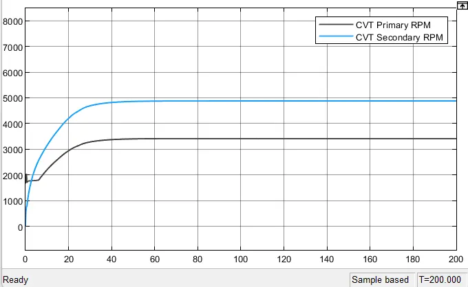
CVT shaft speed
Speed , distance plot
Model 2: cvtModel_dashboard
The model is similar to, "cvtModel" with addition of dashboards.
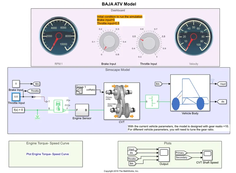
- in this model we can vary the brake and throttle input when the simulation is running . knob block is used to change input and circular guage block is used for visualization of rpm and vehicle speed . simulation running time is set to 'inf' .
RESULTS of model 2 :
the results obtained when we run the model while changing the throttle and brake input .
Engine RPM
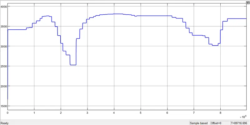
CVT shaft speed
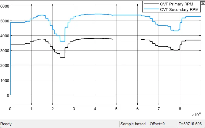
Speed , distance , brake , throttle plot
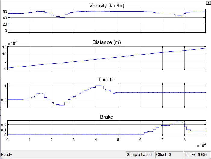
Model 3 : cvtModel_cvtratio_rpm
Contains model based on cvt ratio and engine rpm lookup table.
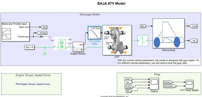
- this model is similar to model 1 with addition of 1-D Lookup table instead of cvtratio signal builder block in model 1 .
- rpm data from engine sensor is taken as input in 1-D lookup table .
- 1 -D lookup table approximate one dimensional function . the parameter for lookup table given below
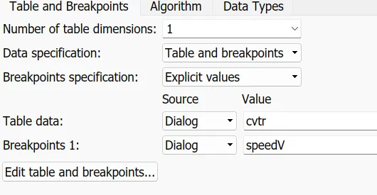
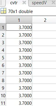
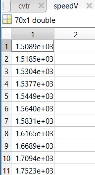
cvtr and speedV data is taken from workspace
RESULTS of model 3 :
Cvt shaft speed
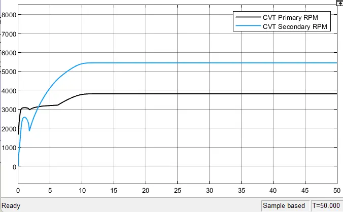
Speed , distance , throttle and brake plot
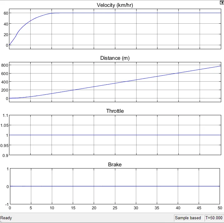
Model 4 : cvtModel_mapped
Contains Simscape model of BAJA ATV with Continous Variable Transmission where the CVT ratio varies based on 1D lookup table.
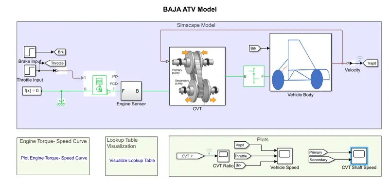
- in this model a step block is used for brake and throttle input .
- gear ratio for this model is 12
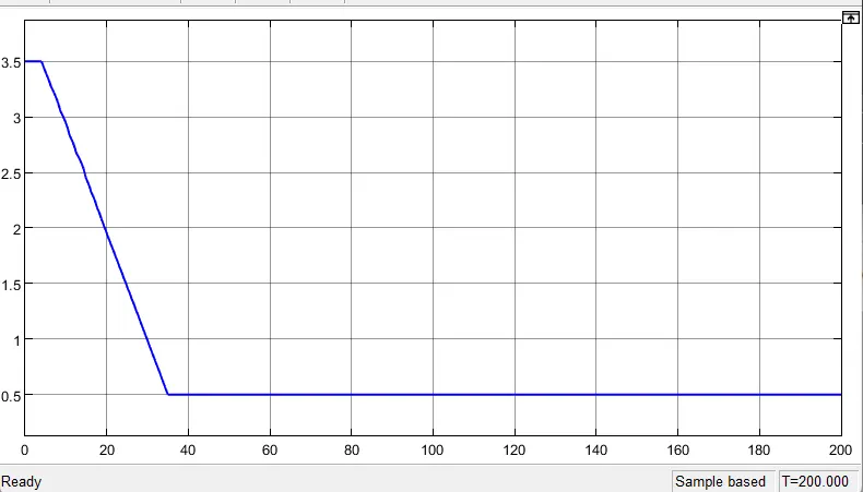
- in CVT subsystem block 1D lookup table is included unlike other models
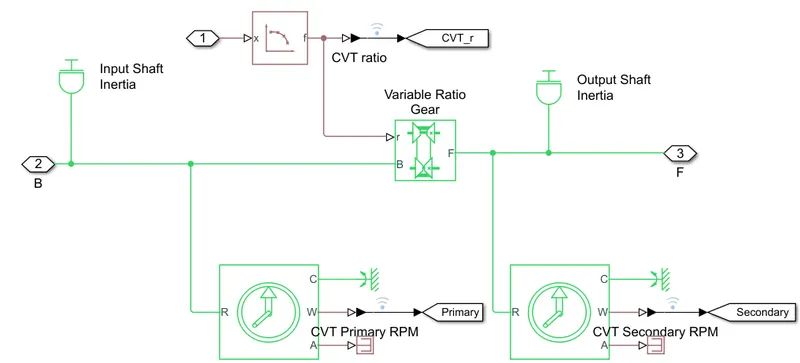
- this model is a closed loop model . here velocity feedback is taken from vehecle body and given as input to lookup table in CVT system .
RESULTS of model 4 :
Lookup table visualization
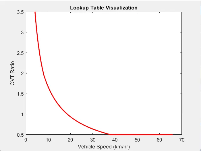
- vehecle speed increases when cvt ratio decreases .
CVT ratio plot
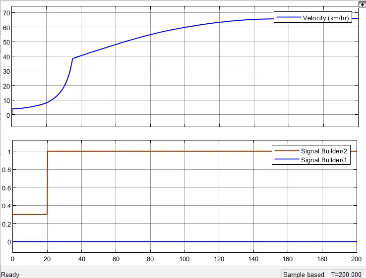
Speed , brake and throttle plot
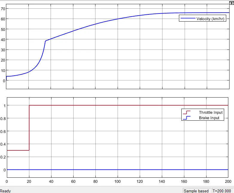
- maximum speed acheived is around 65 km/hr .
- brake input is always 0 and throttle input changes to 1 after 20 seconds and so the speed .
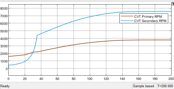
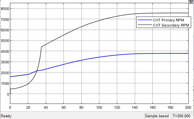
CVT shaft speed
Model 5 : cvtModel_dashboard_mapped
The model is similar to, "cvtModel_mapped" with addition of dashboards.
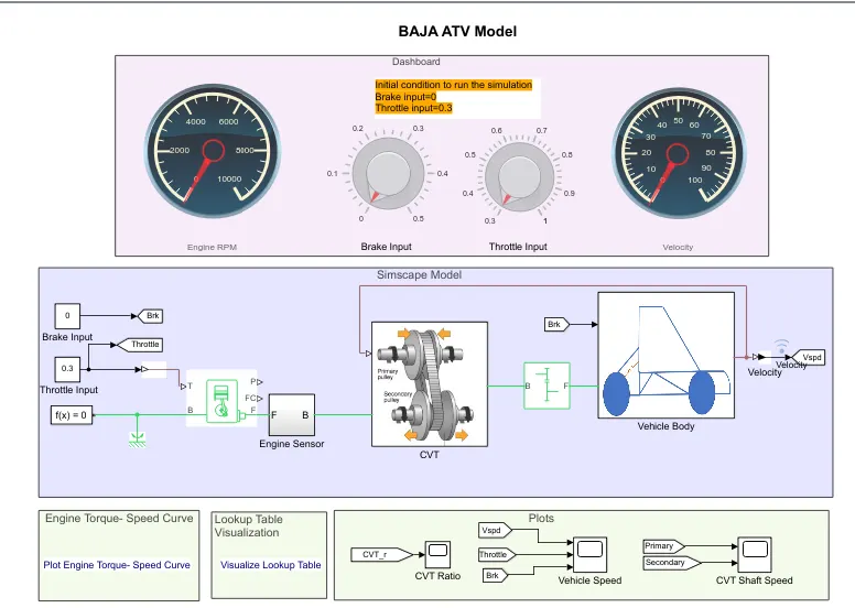
- in this model we can vary the brake and throttle input when the simulation is running . knob block is used to change input and circular guage block is used for visualization of rpm and vehicle speed . simulation running time is set to 'inf' .
RESULTS of model 5 :
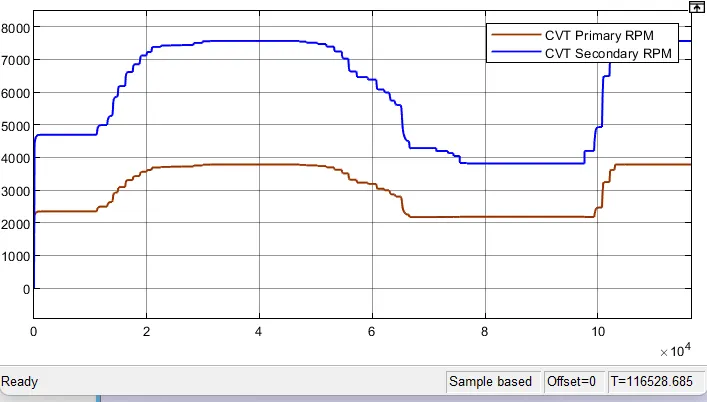
the results obtained when we run the model while changing the throttle and brake input .
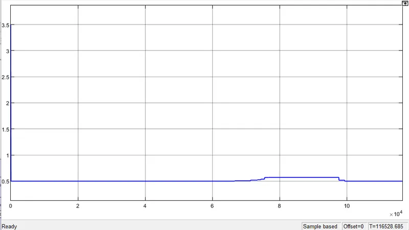
CVT ratio
Speed , brake and throttle plot
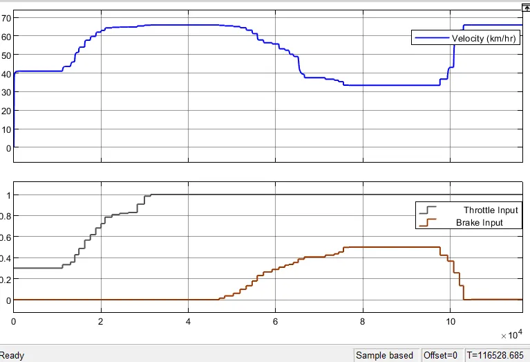
- vehecle speed is highest when throttle is 1 and brake is 0 .
CVT shaft speed
Model 6 cvtModel_data
The model is used to log the CVT ratio and vehicle speed for the look table visualization
CVT Ratio
- using signal builder block this signal created and cvtr array was created and saved in it by using ' to workspace ' block .
RESULTS of model 6
Vehicle speed , brake and throttle plot
CVT shaft speed
CONCLUSION :-
we have successfully carried out simulation of all models of all terrain vehecle and results are satisfactory .
REFERENCE:-
wikipedia
https://www.mathworks.com/matlabcentral/fileexchange/70576-baja-all-terrain-vehicle-atv-model
https://youtu.be/gOFweQcz0XI