Project
Project - System-level Simulation of an All-terrain vehicle.
AIM :- to study and analyze the BAJA All Terrain Vehicle (ATV) model using Simulink and compare between different models. There are two configurations considered in the study
- Open loop configuration where the CVT ratio is varied randomly and effect of vehicle performance is analysed.
- Closed loop configuration where CVT ratio is selected based on look up table.
OBJECTIVE :
- To prepare a technical report explaining the functions of the subsystems & blocks used for preparing the model
- To Explain in detail all the differences between all the five models provided
- To understand and comment on the results.
WHAT IS BAJA SAE : (<<---click here)
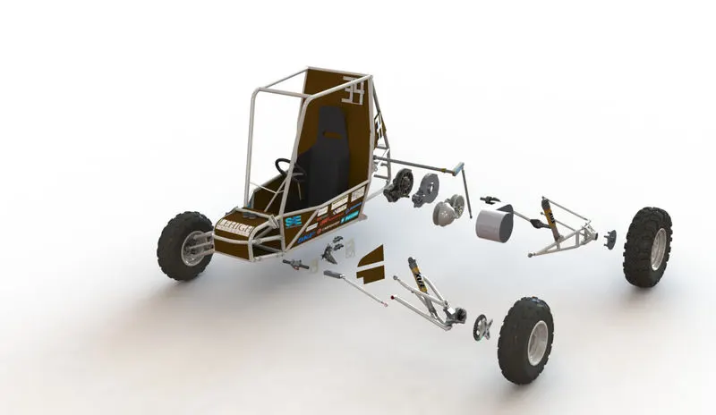
Baja SAE is an collegiate design series competition run by the Society of automotive engineers (SAE international). Teams of students from universities all over the world design and build small off-road cars. The cars all have engines of the same specifications. As of 2018 the engine has been an unmodified briggs and stratton Model 19 Vanguard engine single cylinder with a displacement of 305cc and power output of approximately 10 bhp (7.5 kW).
The goal in Baja SAE racing is to design, build and race off-road vehicles that can withstand the harshest elements of rough terrain. The vehicles used in Baja SAE racing are often similar in appearance to dune buggies. Before 2007, the events were called "Mini Baja".
This model helps to explore and analyse various designs and parameters. This simplified simulation model can be further extended to model real world conditions.
CVT :
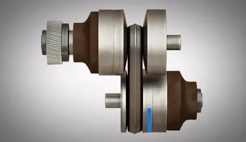
A CVT or Continuously Variable Transmission is an automatic, single-speed, and gearless transmission that can shift through an infinite number of gear ratios.
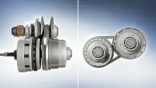
A continuously variable transmission (CVT) is a transmission that operates on an ingenious pulley system that automatically varies the transmission ratio, allowing an infinite variability between highest and lowest gears with no discrete steps or shifts. CVTs provide more useable power, better fuel economy and smoother driving experience than traditional transmissions that use gearboxes with fixed numbers of gear sets.
- CASE 1 - ATV with CVT without dashboard
OPEN LOOP CONFIGURATION
In open loop configuration CVT ratio is given randomly and not based on vehicle performance. The Simulink model of BAJA ATV operating in open loop mode is shown below. Here the brake input and throttle input is given in two modes.
One model uses signal builder block ie without dashboard and whereas other model (i.e. model with dashboard) uses circular gauge to give constant value of throttle and break input. n the third model, a look up table is created based on the values of vehicle velocity(km/hr) and CVT RATIO. Signal builder block used in the previous configuration is replaced by CVT look up table.
The major components of the system include
- Engine model
- CVT
- SIMPLE GEAR
- VEHICLE BODY
for this system brake and throttle inputs are given via signal buider. The gear ratio input to the CVT subsystem is also provided via signal builder. CVT subsystem has two ideal rotational motion sensor to measure the motion of the shaft and it has variable gear ratio box which provide gear ratio to the two shafts. Respective model and output plot for the case 1 is as shown below.
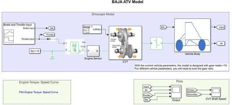 <<--Fig 1 SIMULINK model of ATV without dashboard
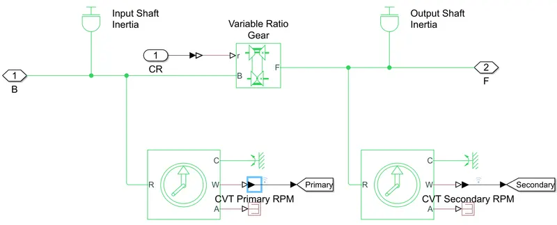 <<--Fig 2 Configuration of CVT subsystem.
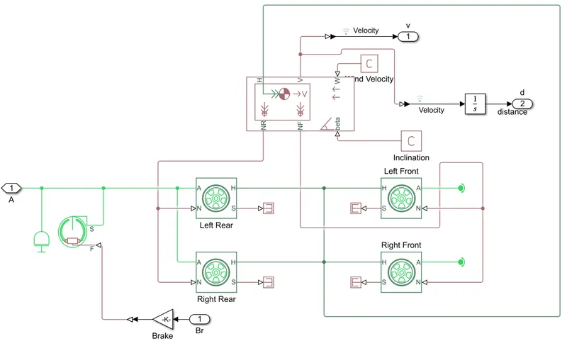 <<--Fig 3 Configuration of Vehicle body subsystem.
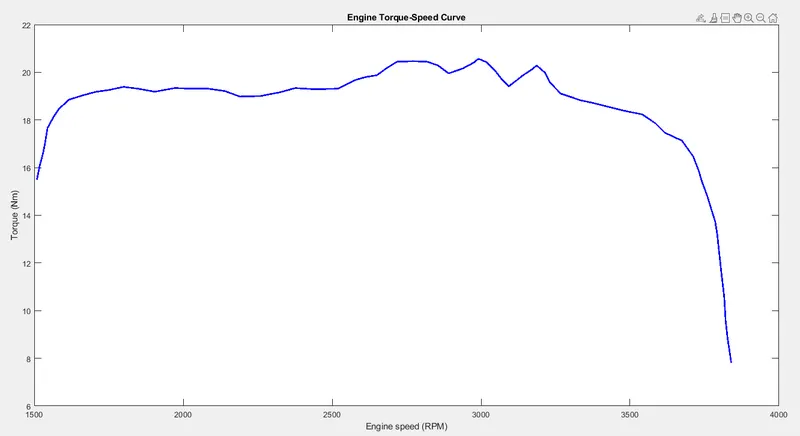 <<--Fig 4 Plot Speed Vs Torque
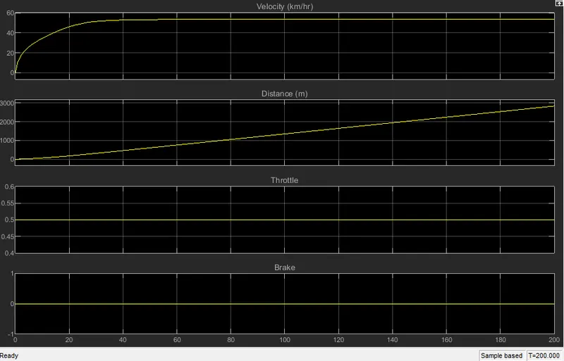 <<--Fig 5 Plot of Velocity, Distance, Throttle and brake
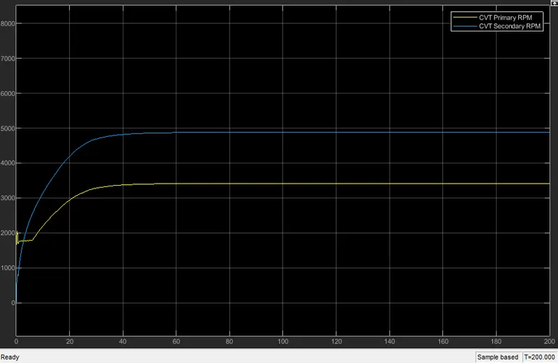 <<--Fig.6 Plot RPM of Primary and secondary shaft.
Brake input to the system is maintained as zero and throttle input is 0.5. We can observe the increase in the velocity initially and then it is constant as throttle is constant. Rotational speed of the secondary shaft is more than the primary shaft because radius of the secondary shaft is large.
- Case 2 - ATV with CVT with dashboard
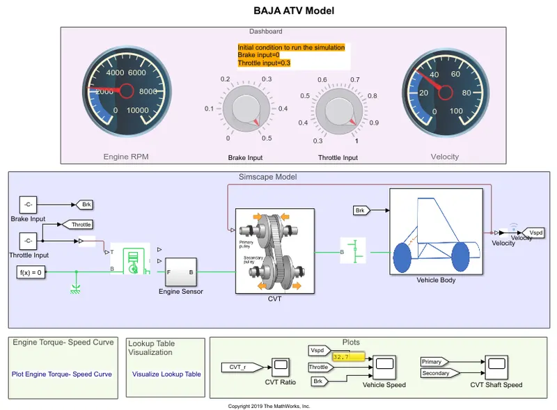
Dashboard is used as input to the system to control brake and throttle. CVT and Vehicle body subsystems looks similar to the Above model. Respective model and output plot for the case2 is as shown below.
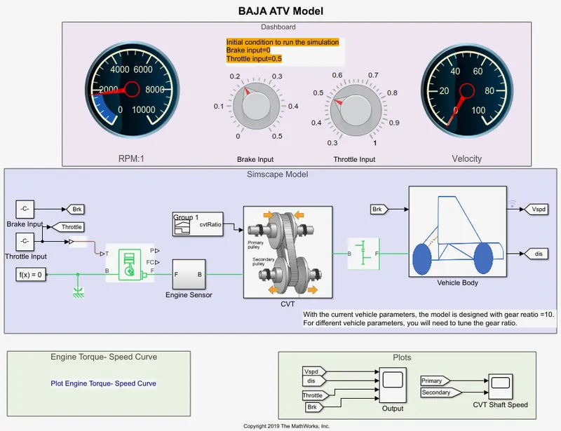 <<--Fig 1 SIMULINK model of ATV with dashboard.
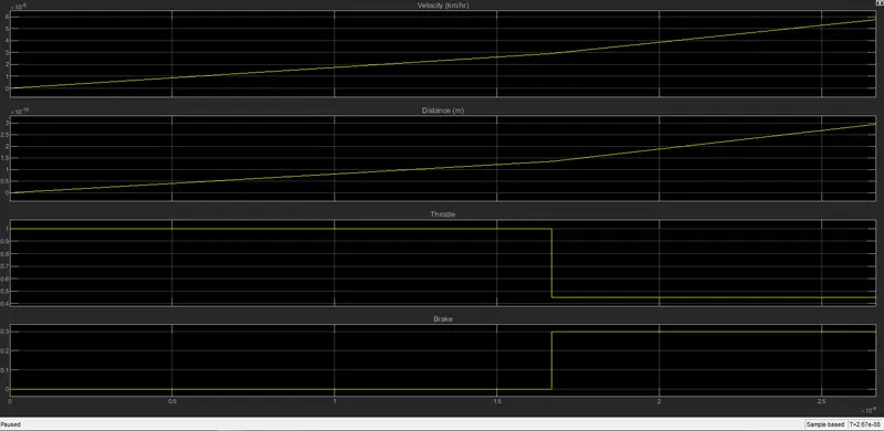 <<--Fig 2 Plot of Velocity, Distance, Throttle and brake
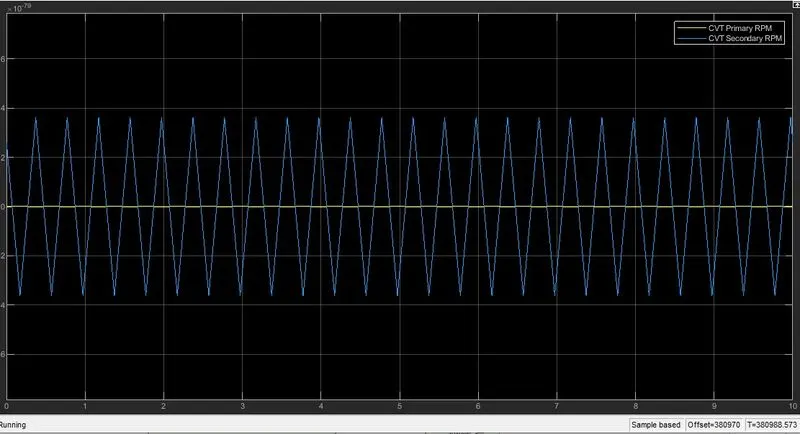 <<--Fig.3 Plot RPM of Primary and secondary shaft.
Here, Brake and throttle can be vary according to our requirement. Initially barke is maintained at zero. Velocity starts decrease as the application of the throttle. Velocity becomes zero as the application of the brake maintaining throttle constant. Rotational speed of primary and secondary shafts are initially high. It reaches zero as the application of the brake.
In case of Simulink model with dashboard throttle and brake inputs are user controlled. Whenever brake input is applied vehicle slows down and based on throttle input given through knob, velocity of vehicle increases.
- Case3 - ATV with CVT without dashboard using lookup table
CLOSED LOOP CONFIGURATION
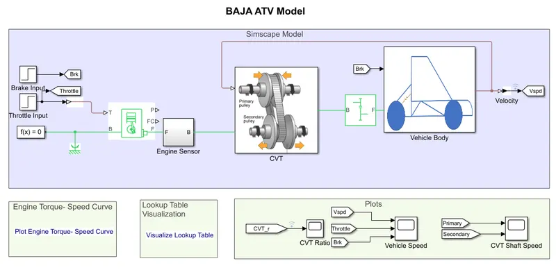
In closed loop configuration CVT ratio is decided by vehicle velocity. This is represented by two ways- without dashboard and with dashboard. A feed back is provided from the vehicle input and based on this input CVT ratio are selected.
The Simulink model of BAJA ATV operating in closed loop Mode (without dashboard) is shown below
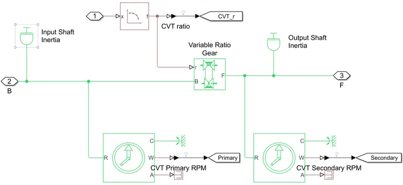 <<--Fig 2 Configuration of CVT subsystem.
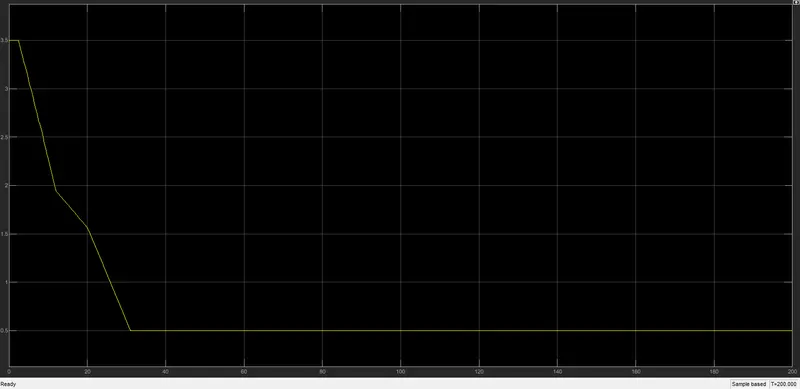 <<--Fig 2 CVT Ratio.
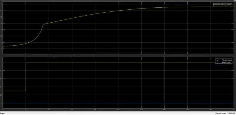 <<--Fig 3 Plot of Vehicle speed (Velocity,Throttle and brake)
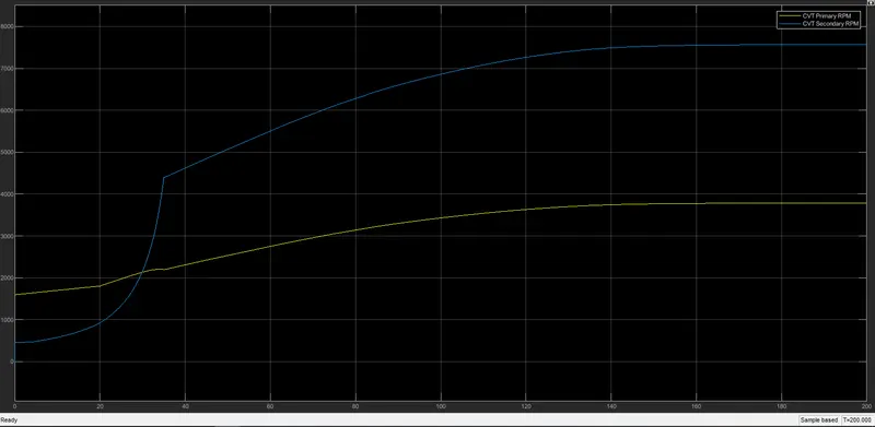 <<--Fig 4 Plot of CVT Shaft Speed in RPM of Primary and secondary shaft.
Brake Input is maintatined at zero state. Throttle input initially 0.3, then it increases to 1 at 20s. We can oberve increase in the velocity as throttle increases. Rotational speed of the secondary shaft is more than the primary shaft. But, we can observe little disturbance in the inital stage because of the lookup table input.
- CASE 4 - ATV with CVT with dashboard using lookup table
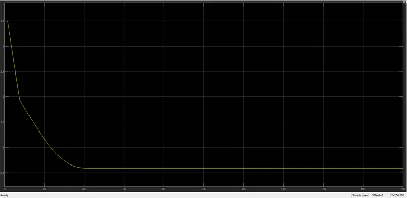 <<--Fig 2 CVT Ratio.
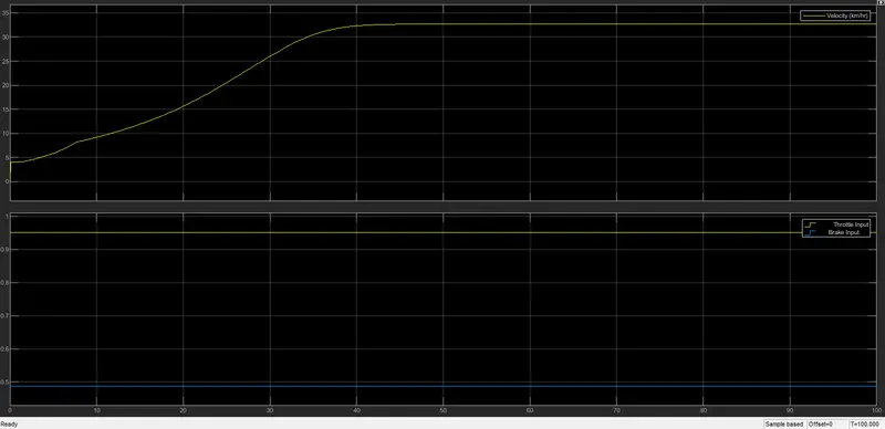 <<--Fig 3 Plot of Vehicle speed (Velocity,Throttle and brake)
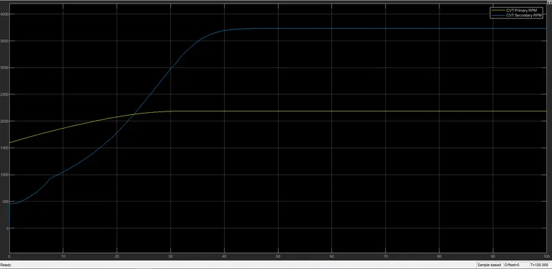 <<--Fig 4 Plot of CVT Shaft Speed in RPM of Primary and secondary shaft.
Brake and Throttle can be vary according to our requirement. Initially Barke is maintained at zero. Velocity starts decrease as the application of the throttle. If Throttle increse, Velocity also increases. Velocity decreases as the application of the brake maintaining throttle constant. As we apply throttle, rotational speed of primary and secondary shafts increases. it decreases as the application of the brake.
VEHICLE MODELING
In vehicle model block parameters such as car mass, frontal area, number of wheels per axle, drag etc can be specified. Tyre modelling is done with default values. However it can be defined for user defined values.
Result :
This technical report details the modelling and simulation of a Continuously Variable Transmission (CVT) BAJA All-Terrain Vehicle (ATV) using Simscape and Simscape driveline. This models help to analyse the effect of various vehicle parameters such as weight, CVT ratio etc on the performance of the vehicle. application of brake and throttle affects to velocity of the vehicle as well as rotational speed of shaft. Application of brake reduces both velocity and rotational speed of shaft. As throttle increses, velocity and shaft speed increses. Performance of closed loop system is better than the open loop system