Project
AIM : Carry out a system-level simulation of an all-terrain vehicle(ATV).
OBJECTIVES :
- To carry out a simulation of ATV.
- To prepare a technical report explaining the model properties and results.
ALL TERRAIN VEHICLE :
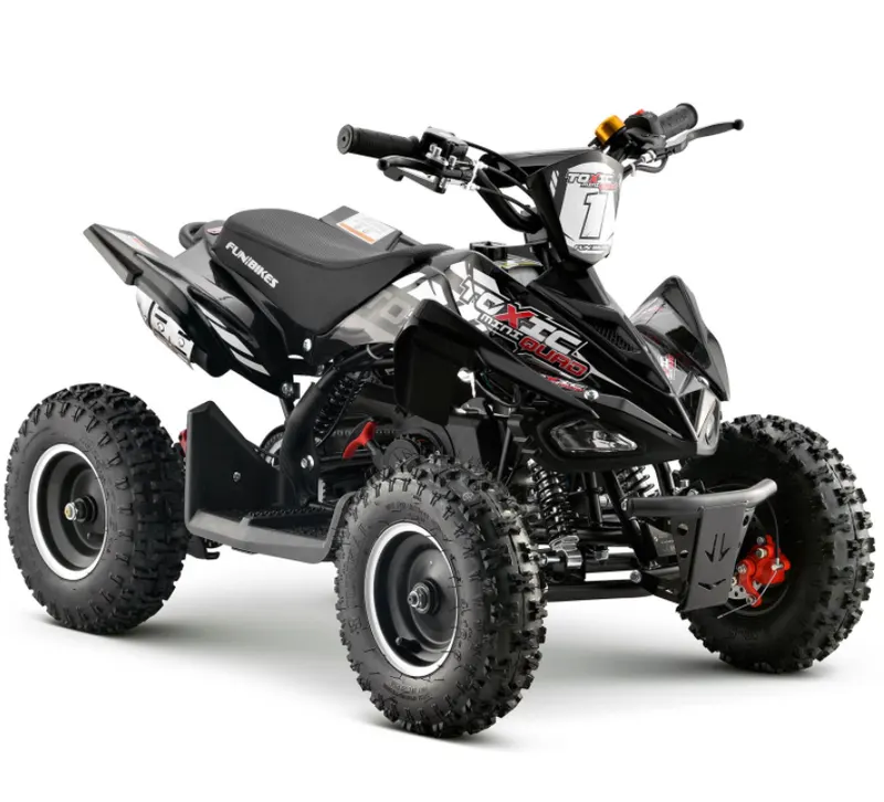
An ATV is defined as a motorised off highway vehicle designed for travel on low pressure or non pneumatic tires having a seat designed for single operator or passenger also it has handlebar for steering control.
ATV is devided into two types as designed by the manufacturers
- ATV is designed for the single operator or single passenger
- ATV is designed for the operator and passenger which has 2 seating arrengements.
General picture of ATV :
Components of ATV :
- Vehicle body
- Engine
- Tire
- Suspension
- CVT, i.e Continuously Variable Transmission.
Model :
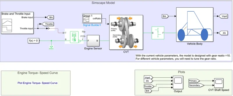
Blocks which is mainly used in the model :
- Signal builder
- Simulink PS convertor
- GoTo
- Generic engine
- solver configuration
- Mechanical rotational referance
- simple gear
- Engine sensor
- chart
- scope
Signal Builder :
The signal builder is a block which used to give the inputs to the model, the block build the input signal which are two inputs named Brake and Throttle input.
Simulink PS convertor :
The block is used for the convert the system or model signal, the signals are mainly two types which are simulink and physical signal, this block is used for convert the physical signal to simulink signal.
Generic Engine:
The block represents the system level model of a SI and Diesel engine suitable for use at the initial stages of the modelling when only the basic parameters are available. it has optional idle speed and red line controller are included.
The trottle speed lies between 0 to 1 , if the engine speed falls down then the torque is blended to 0 and when the speed exceeds to maximum then simulation stops and shows the error message.
Engine Sensor :
This sensor is connected to the generic engine and it consist of,
- Physical modeling connection port
- Ideal mechanical rotational sensor measures the angular velocity
- PS terminator block which is used to terminate physical signal outputs
This sensor is then connected to the CVT subsystem
Simple Gear :
It consist of fixed ratio gearbox, no inertia or compliance modelled in this block. It consist of gear meshing, backlash, viscous bearing losses.
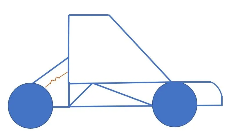
Vehicle Body :
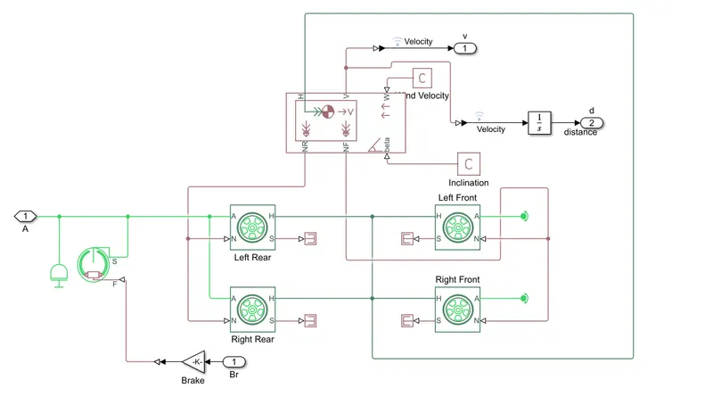
A vehicle body is represents a two axle body in longitudinal motion, the block consist of body mass, aerodynamic drag, road incline and weight distribution to axle.
It consists of four wheels which is two connected to the front axle and other two are to rear axle, the rear wheels is connected to the double shoe brake.
Vehicle body Subsystem :
Suspension :
Suspension is the system of tires, tire air, springs, shock absorbers, and linkages that connects a vehicle to its wheels and allow relative movement between the two. Suspension systems must support both road holding/handling and ride quality, which is at odds with each other.
CVT, i.e Continuously Variable Transmission :
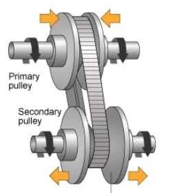
The CVT mainly consist of Primary pully, secondary pully, variator, belt etc
- If the primary pully moves inward and the secondary pully moves outward then it will lead to overdrive
- If the primary pully moves outward and the secondary pully moves inward then it will lead to speed reduction.
CVT subsystem :
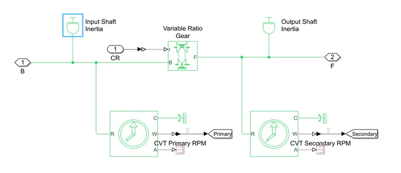
This CVT subsystem consist of various blocks such as input and output shaft inertia, variable gear transmission, ideal rotational motion sensors and PS terminator along with mechanical rotational reference.
Here we need to do the following Studies :
- BAJA ATV model without Dashboard
- BAJA ATV model with Dashboard
- BAJA ATV model using the lookup table without Dashboard
- BAJA ATV model using the lookup table with Dashboard
Study 1 :
- BAJA ATV model without Dashboard
#Model
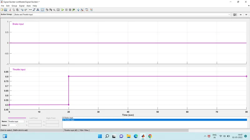
Signal Builder :
Brake input is constant i.e. 0 with the 80 sec of time
Throttle input is 0.5 for first 20 sec later increase to 0.8 for remaining time
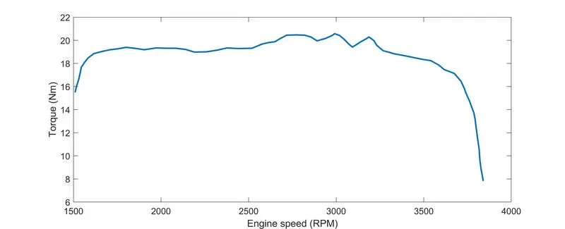
Engine Torque speed curve :
CVT Ratio :
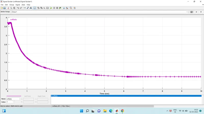
Output Results :
CVT Shaft Speed :
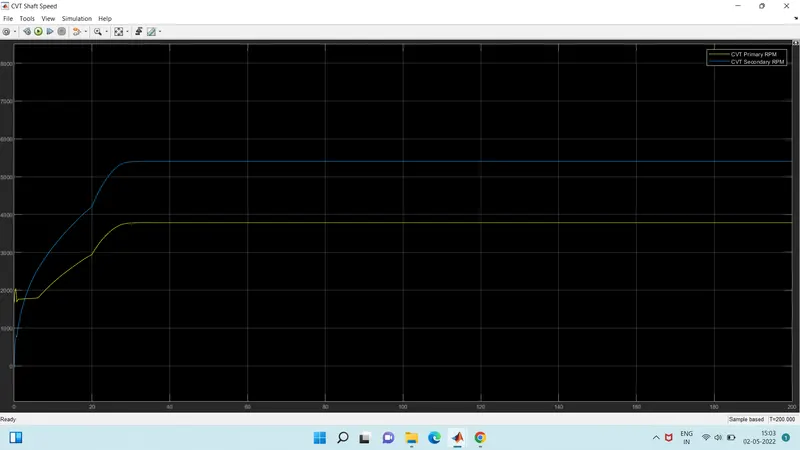
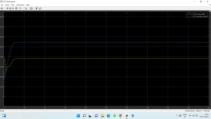
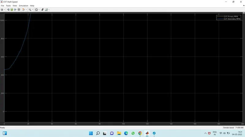
The CVT shaft speed shows variations of speed of primary and secondary pully.
Engine RPM :
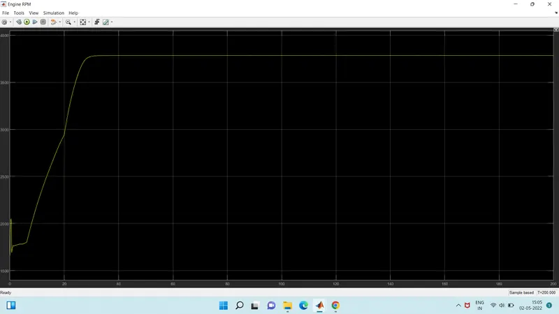
Output Velocity, Distance, Throttle, Brake :
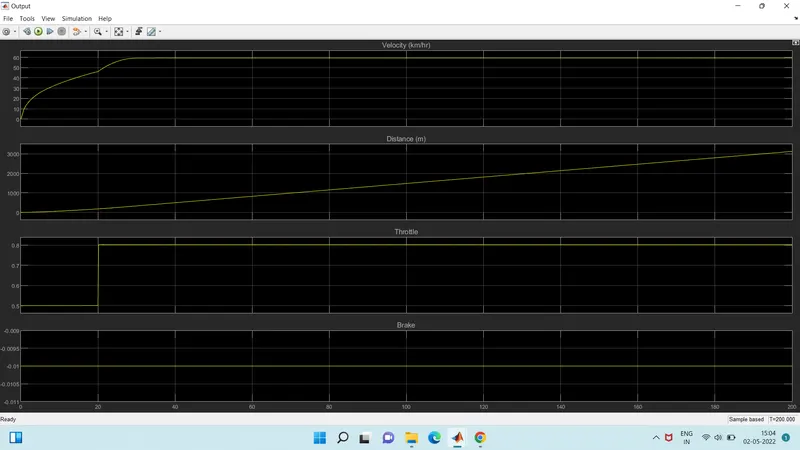
while providing throttle input if the value is 0.3 then the velocity shows a sudden drop in the speed because of that the value of throttle is changed to 0.5 then we get smooth flow of velocity which is almost constant.
#Study 2
- BAJA ATV model with Dashboard
Model :
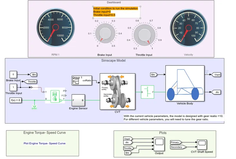
Explanation :
- This model is similar to that of the previous one, the one extra that is added over here is dashboard which has brake and throttle input knobs that allows the user to change the input values while the simulation is running.
- We kept the brake input as 0,where the trottle keeps on changging based on the input by the user.
- The change in throttle inputs results in the changes in the vehicle speed which varies simultaniously with it.
Output Results :
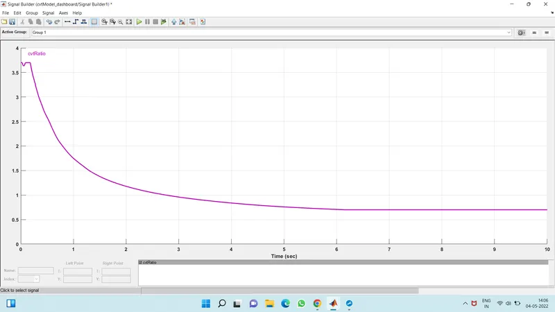
CVT Ratio :
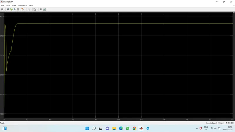
Engine RPM :
CVT Shaft Speed :
Output Velocity, Distance, Throttle, Brake :
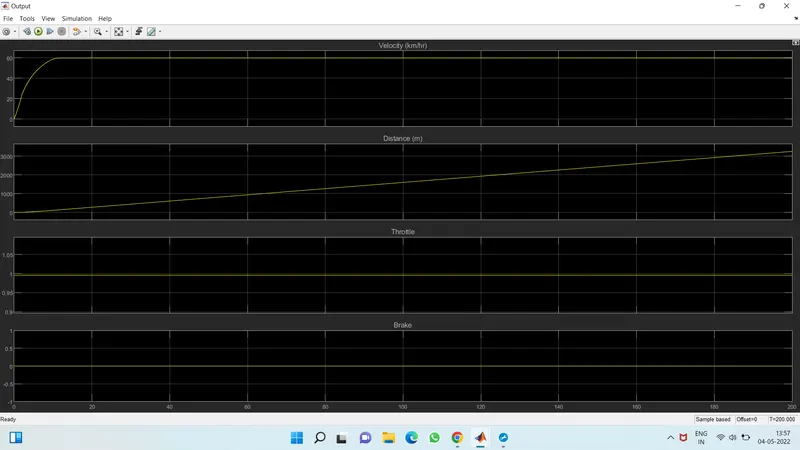
In this above study we take the brake input as 0 and the throttle input is adjusted on the knob, whenever the throttle value changes the velocity changes automatically.
#Study 3
- BAJA ATV model using the lookup table without Dashboard
Model :
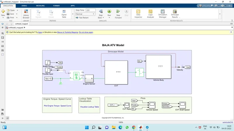
Explanation :
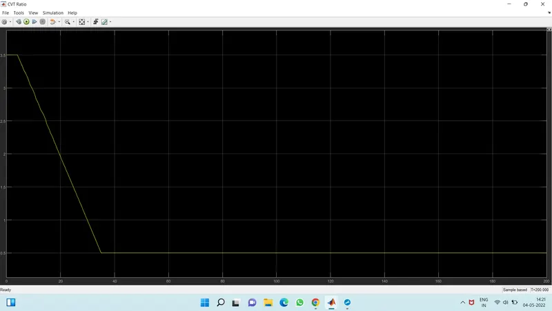
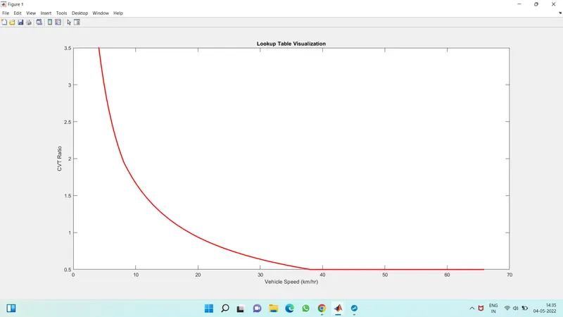
- In this model the brake and throttle use a step signal as an input. Having a lookup tablewith CVT ratio vs vehicle speed as a visualization table helps to specify the CVT ratio.
- Then model runs for 200 sec and gave us the output in the form of various plots.
- Then the outputs are engine speed, vehicle speed, and CVT shaft speed.
Output Results :
CVT Ratio :
Vehicle Speed :
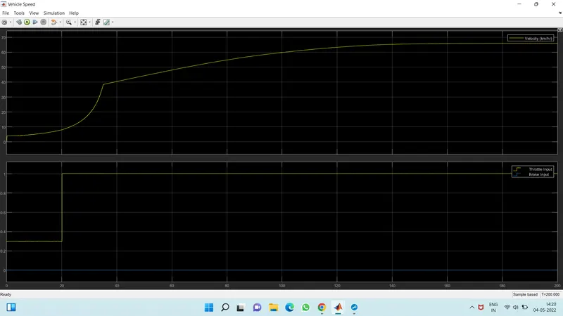
In this brake input is 0, and throttle input is 0.3 for 20 sec and later is 1. the velocity of the vehicle shows gradual growth for the first 20 sec and later on it, increases from 20-40 sec still the speed gets stable.
CVT Shaft Speed :
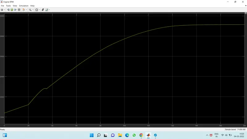
Engine RPM :
#Study 4
- BAJA ATV model using the lookup table with Dashboard
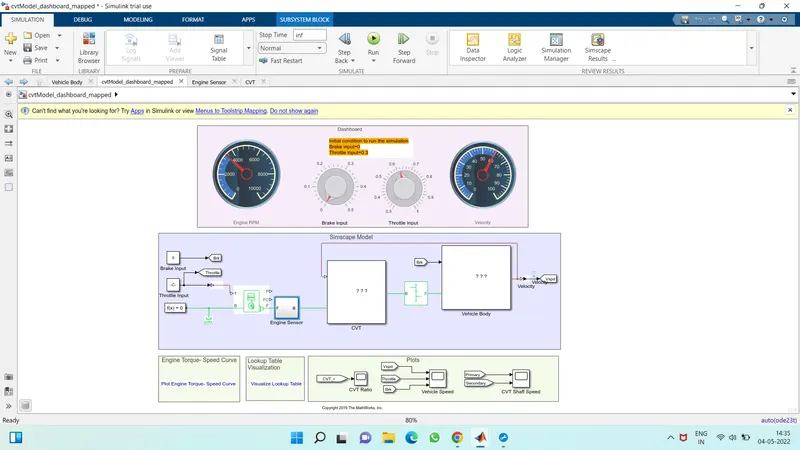
Model :
Explanation :
- This model is similar to the previous model, the only difference is the present of dashboard along with lookup table.
- Here the inputs can be given using the knobs on the dashboard the first is for brake and other is for throttle.
- Here the brake input is 0 and throttle input change their value during run the simulation
- The lookup table values need to be arranged upon their work
- We simulated for an inf period and gave throttle input to get the final result.
Lookup table Visualization for both studies :
Conclusion :
We ran a system level simulation for a BAJA All-Terrain Vehicle(ATV) model by using CVT with or without dashboard and lookup table based on the above obtained results, in the form of engine speed, vehicle speed, velocity, throttle, brake, CVT shaft ratio etc and determine the vehicles performance.
References :
- The BAJA All-Terrain Vehicle(ATV) Model
- GitHub File