Project
AIM
To Carry out a system-level simulation of an all-terrain vehicle.
To study and analyse the BAJA ATV model using simulink.
OBJECTIVES
- To prepare a technical report of BAJA ATV model with and without look up table.
INTRODUCTION
ALL TERRAIN VEHICLE (ATV)
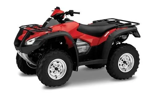
An all-terrain vehicle (ATV), also known as a light utility vehicle (LUV), a quad bike, or simply a quad, as defined by
the American National Standards Institute (ANSI); is a vehicle that travels on low-pressure tires, with a seat that is straddled
by the operator, along with handlebars for steering control. As the name implies, it is designed to handle a wider variety of
terrain than most other vehicles. Although it is a street-legal vehicle in some countries, it is not street-legal within most states,
territories and provinces of Australia, the United States or Canada.
By the current ANSI definition, ATVs are intended for use by a single operator, although some companies have developed ATVs
intended for use by the operator and one passenger. These ATVs are referred to as tandem ATVs.
The rider sits on and operates these vehicles like a motorcycle, but the extra wheels give more stability at slower speeds. Although
most are equipped with three or four wheels, six-wheel models exists and existed historically for specialized applications.
Multiple-user analogues with side-by-side seating are called utility terrain vehicles (UTVs) or side-by-sides to distinguish the classes
of vehicle. Both classes tend to have similar powertrain parts. Engine sizes of ATVs currently for sale in the United States (as of 2008
products) range from 49 to 1,000 cc .
BAJA ATV MODEL WITHOUT DASHBOARD
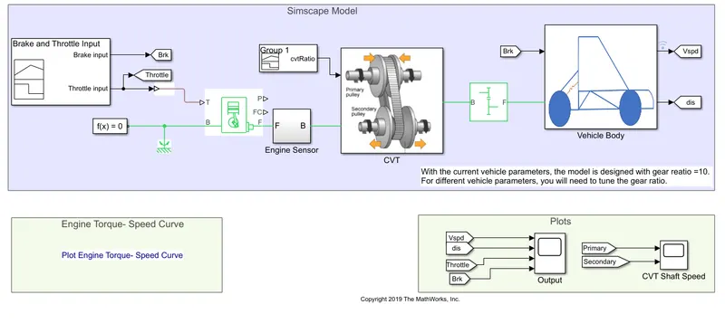
MAJOR COMPONENTS USED IN THE SIMULATION
GENERIC ENGINE :-
Represents a system-level model of spark-ignition and diesel engines suitable for use at initial stages of modeling when only
the basic parameters are available. Optional idle speed and red line controllers are included.
The throttle input signal T lies between zero and one and specifies the torque demanded from the engine as a fraction of the
maximum possible torque. If the engine speed falls below the Stall speed, the engine torque is blended to zero. If the engine
speed exceeds the Maximum speed, the simulation stops and issues an error message.
Connections F and B are mechanical rotational conserving ports associated with the engine crankshaft and engine block,
respectively. Connections P and FC are physical signal output ports through which engine power and fuel consumption rate are
reported.
CVT TRANSMISSION :-
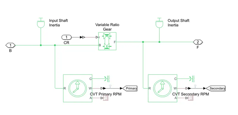
In countinous variable transmission(CVT) the variable diameter pulley plays a vital role in transmission.it must always comes in
pairs.One of the pulleys ,known as the drive pulley is connected to the crank shaft of the engine .The driving pulley is also called
the input pulley ,when it's energy from the engine enters the transmission .since the first pulley is turing the second one it is -
called the driven pulley. The driven pulley transmit the energy to the drive shaft.
VEHICLE BODY
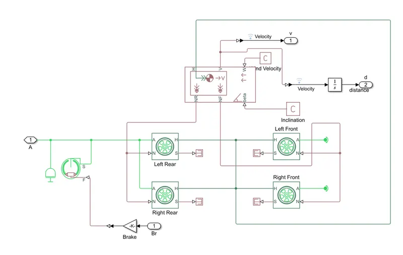
Two axle vehicle with longitudinal dynamics and motion with adjustable mass,geometry and drag properties .The vehicle
can have the same or a diffrent number of wheels on each axle .For eg; two wheels on the front axle and one wheel on
the rear axle .The vehicle wheels are assumed identical in size.
BLOCKS USED
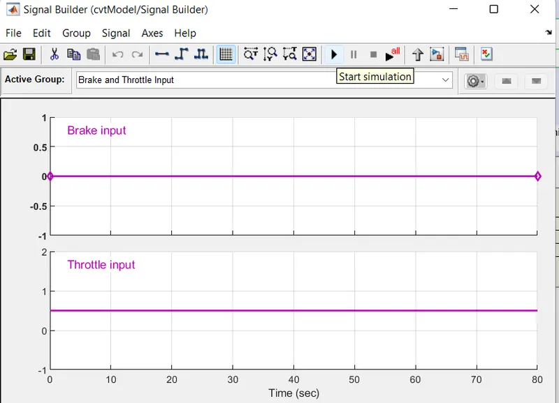
- SIGNAL BUILDER :- Used to input the brake,throttle and CVT ratio.
- Simulink to PS converter :- To convert the simulink signal in to physical system simscape enviornment.
- Solver Configuration :- To specify the solver parameter while the simulation begins.
- Mechanical Reference :- To make sure all the mechanical components are clamped in to the ground.
- Generic Engine :- To run the engine with speed and torque values as input .
- Scope :- To analyse and study the graph of the input/output parameters.
- Display:- To view the calculated engine power.
- Inertia :- To represent the solid inertia.
- Rotational Motion Sensor :-To sense the rotary motion from the engine and give output as RPM.
- Variable Gear Ratio:- To vary the speed according to the gear ratios.
- PS Terminator :- Terminator for unconnected physical signal inputs.
- Double shoe brake:- To apply the brake when needed.
- Constant :- To generate constant signal.
- Tire :- For transporting the vehicle structure.
- Look up table :- To insert the CVT values from the workspace.
- Step :- To increase or decrease an input value for a difined time interval.
FLOW PROCESS
- The throttle signal is generated by the signal builder block and inputed to the generic engine.
- The torque and speed vector are inputed from the MATLAB workspace.
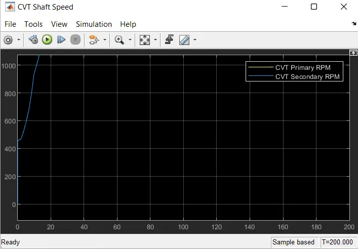
- The engine will generate the output rpm which we can taken from the crank shaft output.
- This is further will be given in to the ideal rotational motion sensor to sense the output rpm.
- The same output speed is given to a simple gear mechanism to reduce the speed where the gear ratio taken is 4 .
- The output speed from the gear reducer will be given to the variable ratio Transmission block.
- Using the signal builder the CVT ratio is given to the respective block.
- The speed is controlled by the variable CVT ratios and the controlled output speed is inputed to the axle.
- The brake signal is generated by the signal builder and inputed to the vehicle body for applying the brake.
- The power from the CVT is inputed to the axle and hence the vehicle get accelarated according to the speed.
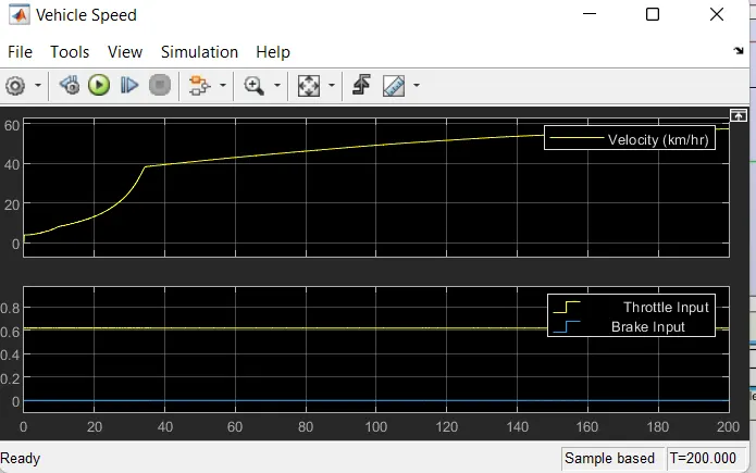
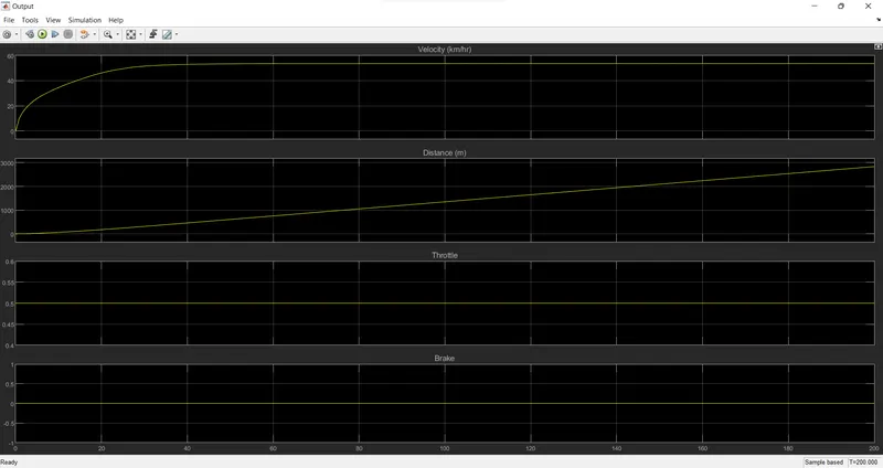
- The velocity is taken as the output for further analysis.
OUTPUT
BAJA ATV MODEL WITH DASHBOARD
MODEL
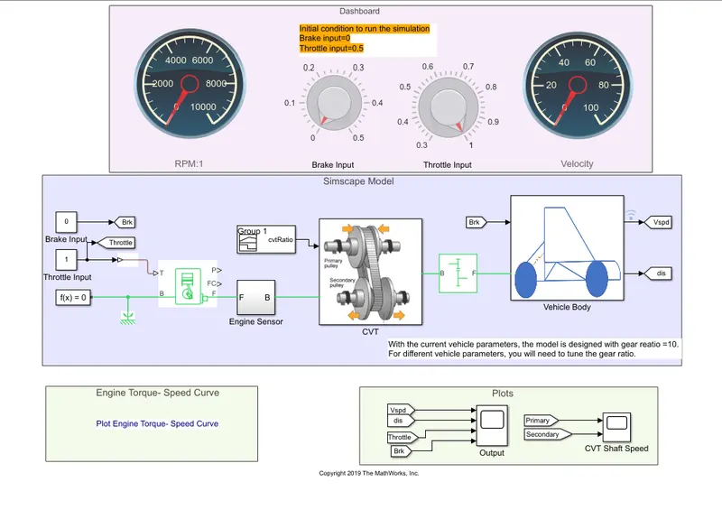
FLOW PROCESS
The model work flow process is same as the process of BAJA ATV model without dashboard ,but the -
throttle and brake inputs are controlled by the user with the knob provided.we can change the inputs brake and -
throttle by changing the knob values provided.
OUTPUT
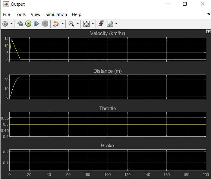
Here i obtained a output by putting a 0.5 of throttle along with 0.1+ of braking.
it can be obtained that the velocity is increasing by increasing the throttle values and decreasing while
increasing the braking values.
BAJA ATV MODEL - DATA EXTRACTION LOOK UP TABLE
MODEL
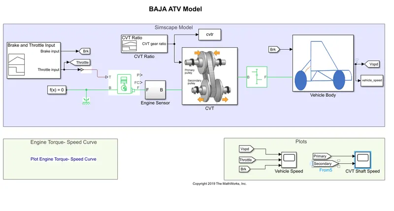
FLOW PROCESS
The model workflow process is same as the process of 'BAJA ATV MODEL WITHOUT DASHBOARD' the change here is
that the CVT ratio and vehicle speed data are extracting from the base workspace.
WORKSPACE
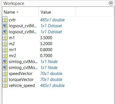
- The output is same as the BAJA ATV model without dashboard.
BAJA ATV MODEL - MAPPED LOOKUP TABLE WITHOUT DASHBOARD
FLOW PROCESS
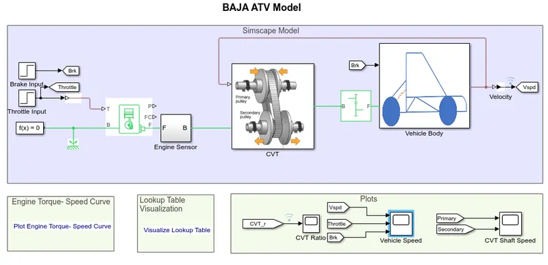
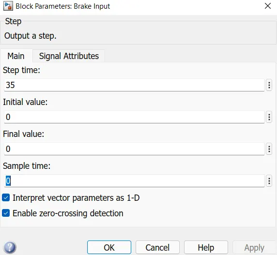
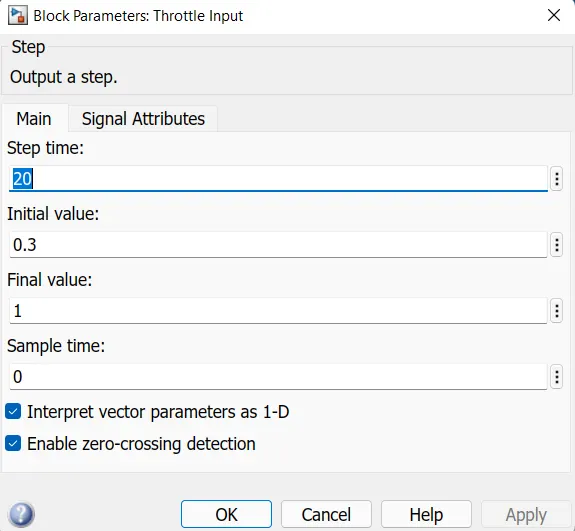
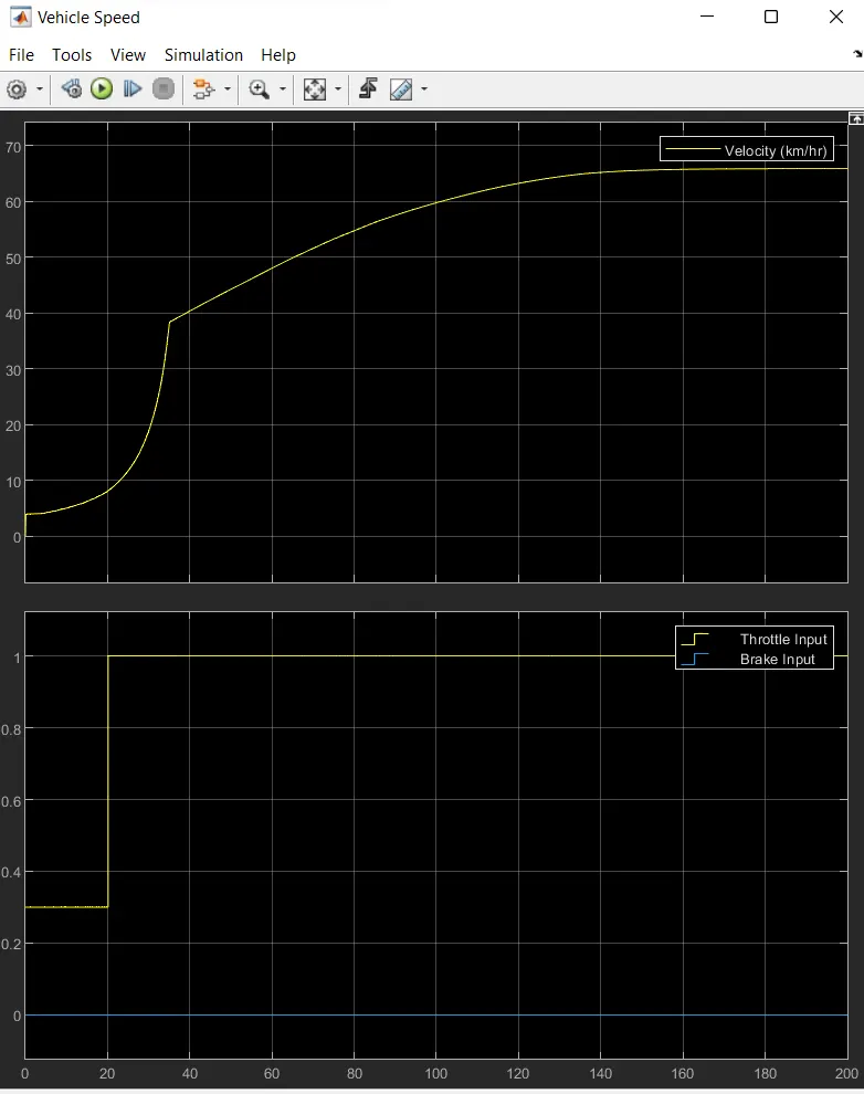
- Instead of signal builder blocks for brake and throttle inputs ,the step blocks are used.At 35 sec the brake input will take
a step value of 0 and at 20 sec throttle input will increase from 0.3 to 1 then remains constant through out.
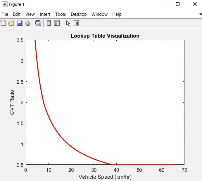
- Instead of signal builder block for CVT ratio the 2D Look up table is used
OUTPUT
BAJA ATV MODEL - MAPPED LOOKUP TABLE WITH DASHBOARD
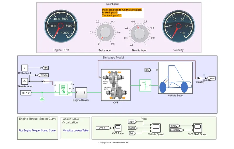
BAJA ATV model mapped lookup table with dashboard is also similar as the process of 'mapped lookup table without dashboard'
here the throttle and break inputs are controlled by the knobs provided in the dashboard.
OUTPUT